Roland DIF-AT: Difference between revisions
→Binwalk / Binvis: added text, images |
|||
| Line 60: | Line 60: | ||
</gallery> | </gallery> | ||
==JTAG/Programming/ | ==JTAG/Programming/CPLD== | ||
The device has two levels of firmware: NOR Flash and CPLD bitstream. The Xilinx is an older model XC95144 which is programmed over JTAG. However, due to the architecture, bitstream cannot be read out over JTAG (even if unlocked) | The device has two levels of firmware: NOR Flash and CPLD bitstream. The Xilinx is an older model XC95144 which is programmed over JTAG. However, due to the architecture, bitstream cannot be read out over JTAG (even if unlocked) it has to use vendor specific tools (Platform Cable USB) | ||
JTAG pads are exposed on the PCB as seen in the image above. I could connect to these to read the CPLD. Pretty soon they were pulled off the board, and I had to solder a pin to the leg temporarily to continue reading data. (before I discovered tiny IC clips!) | |||
[Only one device is visible in the JTAG chain, the Xilinx. The CPU, H8300H (Hitachi/Renesas) is not equipped with JTAG at all. Low level CPU operation is done through a bootloader mode] | |||
I connected to the Xilinx XC95144 using Bluetag, OpenOCD and XC3SPROG (open source Xilinx CLI) and was eventually able to read back ID codes and find IR Len etc. I was happy it was responding. It was fun, confusing and difficult to set up all these tools. I set most of them up on a Raspberry Pi as dedicated hacking server so I can connect remotely to the hot mess setup with my laptop, somewhere more comfortable : ) | |||
It seems strange to me that, this is a 100 pin CPLD, and only 4 inputs and 4 outputs are used! (solely RBUS data, 8 channels L/R in/out). Counter output from H8300H goes to clock pin of the Xilinx, through an inverter. | |||
<gallery> | <gallery> | ||
File:XC3SPROG id read.png|alt=XC3SPROG id read|'''XC3SPROG id read''' | File:XC3SPROG id read.png|alt=XC3SPROG id read|'''XC3SPROG id read''' | ||
| Line 78: | Line 78: | ||
</gallery> | </gallery> | ||
===BSDL Scan=== | ===BSDL Scan -=== | ||
After initial ID code read, I used a [https://github.com/viveris/jtag-boundary-scanner BSDL GUI] to determine whether the CPLD was actually passing data throughput. Whilst easy to use when running, this tool took a while to set up (I mistakenly compiled it from source in Windows 7 32 bit - somehow missing the fact there there was a package release) After downloading the BSDL language file from Xilinx and setting up the tool with info from the Xilinx datasheet (super confusing naming convention, cells vs physical pins). Scanner could only run with this set up in | After initial ID code read, I used a [https://github.com/viveris/jtag-boundary-scanner BSDL GUI] to determine whether the CPLD was actually passing data throughput. Whilst easy to use when running, this tool took a while to set up (I mistakenly compiled it from source in Windows 7 32 bit - somehow missing the fact there there was a package release) After downloading the BSDL language file from Xilinx and setting up the tool with info from the Xilinx datasheet (super confusing naming convention, cells vs physical pins). Scanner could only run with this set up in Extest mode (OS not present nor running) toggling the input pins at a user defined frequency - means the corresponding output logic pulses accordingly. | ||
It was satisfying to see my logic probe light up on the outputs during | It was satisfying to see my logic probe light up on the outputs during Extest scanning. | ||
Xilinx CPLD confirmed working - big achievement! (Not tested in actual operation | Xilinx CPLD confirmed working - big achievement! (Not tested in actual operation) I'm 99% sure its fine after these tests. | ||
At some point I will get a Xilinx Platform Cable to attempt to read the bitstream for archival purposes. However at this stage I'd had to get a few probes etc and didn't really want to get a Xilinx only device. I've had great luck with unlocked devices so far though, everything I've looked at has been open or level 1 : ) | At some point I will get a Xilinx Platform Cable to attempt to read the bitstream for archival purposes. However at this stage I'd had to get a few probes etc and didn't really want to get a Xilinx only device. I've had great luck with unlocked devices so far though, everything I've looked at has been open or level 1 : ) | ||
<br /> | <br /> | ||
[[File:VIVERIS BOUNDARY SCANNER.png|thumb|Viveris JTAG Boundary Scanner]] | |||
==Extract Firmware== | == Extract Firmware - == | ||
| Line 98: | Line 96: | ||
After I desoldered the other half using hot air, I could proceed to read out the contents - | After I desoldered the other half using hot air, I could proceed to read out the contents - | ||
<br /> | <br /> | ||
=== TL48 Programmer- === | ===TL48 Programmer-=== | ||
I used a TL48 programmer with a 48pin TTSOP to read the NOR Flash firmware contents - | I used a TL48 programmer with a 48pin TTSOP to read the NOR Flash firmware contents - | ||
| Line 113: | Line 112: | ||
[[File:DIF AT FLASH SETTINGS.png|thumb|T48 programmer settings and dump - note the very interesting strings!]] | [[File:DIF AT FLASH SETTINGS.png|thumb|T48 programmer settings and dump - note the very interesting strings!]] | ||
=== Binwalk / Binvis - === | |||
I slowed down a bit here because I had no idea how to actually load the file I'd dumped to look at it. First I used Binwalk, which I think is more suited to SOC work. Anyway Binwalk was able to provide a nice image showing the entropy of the file - low entropy = low chance of corruption or encryption (or possibly I'm defining that the incorrect way around) | |||
I also had a look at [https://binvis.io/ Binvis]. Binvis makes for a stunning visual representation, regardless of anything else at all. I love it. It was fun to see the strings represented in coloured pixels. Also, very apparent to see in Binvis, are the banks. This firmware is banked and split. This is to facilitate DFU - the device can be firmware updated by the user while still maintaining stable OS. Then switch a flag to change/denote active bank. | |||
This device has two firmware version strings visible in the firmware (at this point the strings are the only thing I've really been able to see) | |||
Appears it was already updated in the field to the last OS version (1.022) from I'm not sure if it then wipes the other bank? Possibly, because the other regions are written with FF. However it was still pretty confusing to navigate around later on; BRA to 0xFF region. I'm still not sure: maybe the Alesis CPLD remaps certain memory addresses at run time? | |||
[[File:Binwalk entropy image.png|left|thumb|Binwalk entropy image looking good - encouraging at least]] | |||
[[File:DIF-AT BINVIS.png|alt=binvis.io|center|thumb|BINVIS The little 'white line defined' area is where the pointer is viewing]] | |||
Revision as of 20:34, 27 April 2026
[Page under construction - as yet incomplete]
PCB photos, Pinouts, Pin header, Device operation, Connections between subsystems. Notes on firmware structure, Machine language monitor program, DFU, firmware extraction, firmware update script (python)

Brief outline -
I bought this device to repair. They are rare, and interesting. It would not respond any longer or be recognised by host hardware. (it runs in conjunction with host digital mixer / host music production device, translating digital audio formats in real time)
I damaged a lot of traces on the device and gave up on it. However, I learned how to micro-solder and became inspired to continue the repair with reverse engineering techniques. This is my first reverse engineering project, though I have worked on modding and repairing before.
Given the device was already non-responsive (and now damaged) -
Goals-
- De-solder NOR Flash and read firmware.
- Determine potential corruption of firmware.
- Re-flash firmware onto new NOR flash (if good).
- Determine operation / potential corruption of Xilinx CPLD and/or Alesis OTP? IC - read contents if possible.
- Analyse firmware for anything interesting.
- Determine and examine / analyse hardware architecture.
- Repair traces, replace ICs. Test.
- Collate information, share research and findings.
PCB Photos -
-
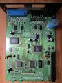 Main board
 -
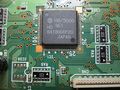 Cpu (not mcu!)
 -
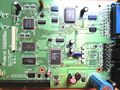 Main board, alt
 -
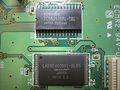 SRAM + NOR Flash (512kb)
 -
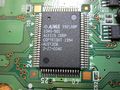 Custom Alesis chip OTP CPLD? GAL?
 -
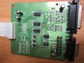 TDIF daughter board
 -
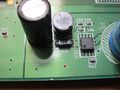 5v power conditioning
 -
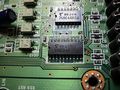 Sync circuitry with optocouplers
 -
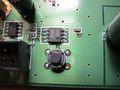 Reset IC and switch
 -
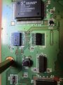 Xilinx CPLD with JTAG pads visible (pin 50, 81 silkscreen)


Device Overview
This is a complex device with a 16 bit CPU, Xilinx 95xx CPLD, Custom Alesis chip (Gate array, PAL, GAL, OTP CPLD?) SRAM, NOR flash 512kb, logic and switching for bus arbitration. BREQ Bus request is a very involved circuit. Also CE# Chip Enable NOR Flash is connected through a complicated muxing circuit. The Alesis custom IC handles the WE# Write Enable to the NOR Flash.
No info could be found on the Alesis chip, searching for the numerous IC markings revealed nothing.
The Device is quite old school. This was built for the early generation of ADAT/TDIF machines, still using physical tape. Thankfully a tape machine is not necessary for operation. The sync requirements of locking digital audio using analogue tape definitely adds complexity to this system.
Device has 2 buttons on the PCB: 1 - RESET, reset circuit and IC 2 - Launch monitor diagnostic mode.
A 50 pin header provides easy access to most address lines and relevant (to operation) CPU/RAM/Flash lines. This will be convenient to run a logic capture during boot and operation later. I beeped out the 50 pin connector - Many pins have multiple connections. Happily; the vias were not tented - this was a long endeavour even with continuity through the vias : ) Below, the findings and some general notes:
-
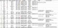 Header pins 1 - 16
 -
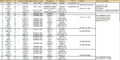 Header pins 16 - 24
 -
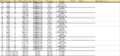 Header pins 15 to 38
 -
 Header pins 38 to 50
 -
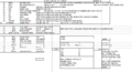 General notes about inferred operation


JTAG/Programming/CPLD
The device has two levels of firmware: NOR Flash and CPLD bitstream. The Xilinx is an older model XC95144 which is programmed over JTAG. However, due to the architecture, bitstream cannot be read out over JTAG (even if unlocked) it has to use vendor specific tools (Platform Cable USB)
JTAG pads are exposed on the PCB as seen in the image above. I could connect to these to read the CPLD. Pretty soon they were pulled off the board, and I had to solder a pin to the leg temporarily to continue reading data. (before I discovered tiny IC clips!)
[Only one device is visible in the JTAG chain, the Xilinx. The CPU, H8300H (Hitachi/Renesas) is not equipped with JTAG at all. Low level CPU operation is done through a bootloader mode]
I connected to the Xilinx XC95144 using Bluetag, OpenOCD and XC3SPROG (open source Xilinx CLI) and was eventually able to read back ID codes and find IR Len etc. I was happy it was responding. It was fun, confusing and difficult to set up all these tools. I set most of them up on a Raspberry Pi as dedicated hacking server so I can connect remotely to the hot mess setup with my laptop, somewhere more comfortable : )
It seems strange to me that, this is a 100 pin CPLD, and only 4 inputs and 4 outputs are used! (solely RBUS data, 8 channels L/R in/out). Counter output from H8300H goes to clock pin of the Xilinx, through an inverter.
-
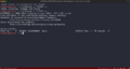 XC3SPROG id read
 -
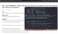 Pullup info from Xilinx
 -
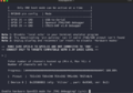 BlueTag correctly reads pins
 -
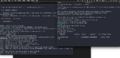 OpenOCD and BlueTag (in BusPirate Mode)


BSDL Scan -
After initial ID code read, I used a BSDL GUI to determine whether the CPLD was actually passing data throughput. Whilst easy to use when running, this tool took a while to set up (I mistakenly compiled it from source in Windows 7 32 bit - somehow missing the fact there there was a package release) After downloading the BSDL language file from Xilinx and setting up the tool with info from the Xilinx datasheet (super confusing naming convention, cells vs physical pins). Scanner could only run with this set up in Extest mode (OS not present nor running) toggling the input pins at a user defined frequency - means the corresponding output logic pulses accordingly.
It was satisfying to see my logic probe light up on the outputs during Extest scanning.
Xilinx CPLD confirmed working - big achievement! (Not tested in actual operation) I'm 99% sure its fine after these tests.
At some point I will get a Xilinx Platform Cable to attempt to read the bitstream for archival purposes. However at this stage I'd had to get a few probes etc and didn't really want to get a Xilinx only device. I've had great luck with unlocked devices so far though, everything I've looked at has been open or level 1 : )

Extract Firmware -
At some point in the repair attempt, I heard a strange flapping sound from the NOR Flash as I moved the device around. ALL of the pins 25 - 48 had detached from the PCB with zero damage to the traces or pins. I surmise that this was the original failure point of the device - dry joints on the Flash chip.
After I desoldered the other half using hot air, I could proceed to read out the contents -
TL48 Programmer-
I used a TL48 programmer with a 48pin TTSOP to read the NOR Flash firmware contents -
In the image below are the settings needed for a good read. The NOR flash is 16 bit wide, but the CPU is reading it in 8 bit mode (8 bit mode pin is tied low). SHARP LH28F400BVE Parallel NOR Flash 512kb. The chip is from the late 1990s as the device is also, turn of the century 2000s.
Although the strings are legible here, this is because the T48 is re-arranging the byte order automatically. The byte order must be swapped (little endian) in order to disassemble the firmware. I found this out after nonsensical strings were seen, without swapping byte order. I tried some 8 bit reads, but this garbled the strings in the T48. It was clear 16 bit wide was correct, but then byte order needed changing. I used a python script to swap the byte order of the entire dumped firmware file.
The strings are very interesting indeed. Not just a standard 'version' or 'release date' string - they are command strings!
As this device has no screen, a low level diagnostic routine is inferred from their discovery. Looking closely at the last string or two, I was worried that it might be corrupted as there are some missing letters in the string - (ADAT Sync port di onnected and Dectected rather than Detected).

Binwalk / Binvis -
I slowed down a bit here because I had no idea how to actually load the file I'd dumped to look at it. First I used Binwalk, which I think is more suited to SOC work. Anyway Binwalk was able to provide a nice image showing the entropy of the file - low entropy = low chance of corruption or encryption (or possibly I'm defining that the incorrect way around)
I also had a look at Binvis. Binvis makes for a stunning visual representation, regardless of anything else at all. I love it. It was fun to see the strings represented in coloured pixels. Also, very apparent to see in Binvis, are the banks. This firmware is banked and split. This is to facilitate DFU - the device can be firmware updated by the user while still maintaining stable OS. Then switch a flag to change/denote active bank.
This device has two firmware version strings visible in the firmware (at this point the strings are the only thing I've really been able to see)
Appears it was already updated in the field to the last OS version (1.022) from I'm not sure if it then wipes the other bank? Possibly, because the other regions are written with FF. However it was still pretty confusing to navigate around later on; BRA to 0xFF region. I'm still not sure: maybe the Alesis CPLD remaps certain memory addresses at run time?

