File list
This special page shows all uploaded files.
| Date | Name | Thumbnail | Size | User | Description | Versions |
|---|---|---|---|---|---|---|
| 02:44, 15 May 2024 | Maxon sd 161.jpg (file) |  |
204 KB | Trevor229 | Maxon SD-161 data radio installed in a CD&F siren controller | 1 |
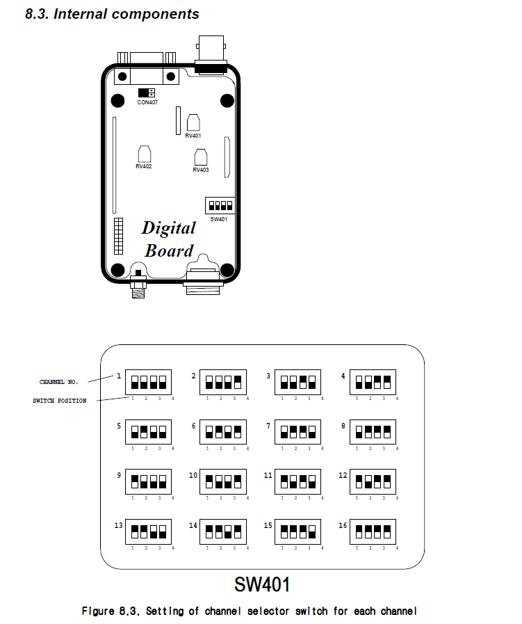
| 23:50, 14 May 2024 | Maxon DIP switch config.png (file) |  |
42 KB | Trevor229 | Channel selection diagram for maxon data radios | 1 |
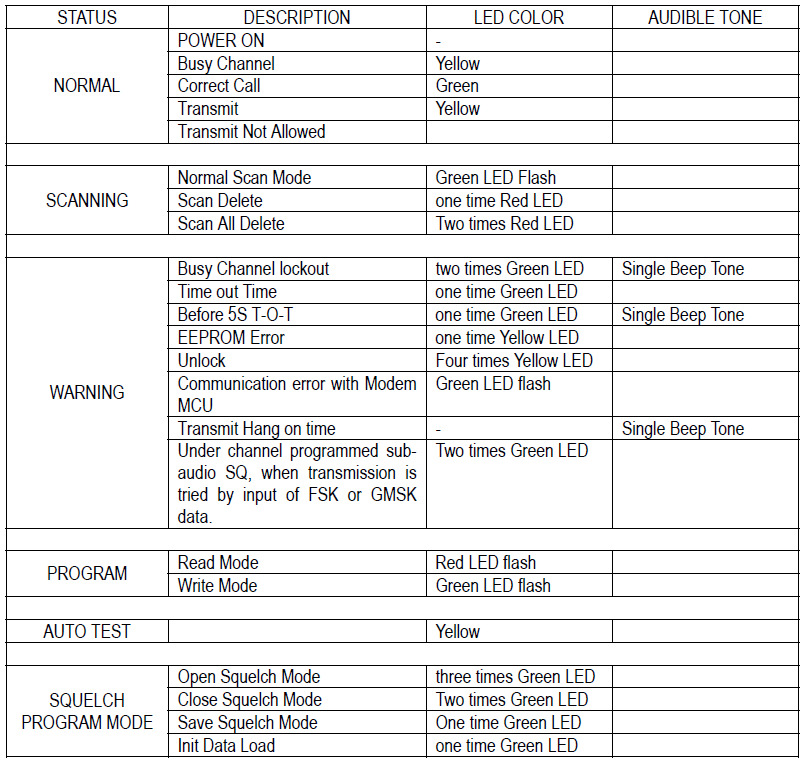
| 23:43, 14 May 2024 | Maxon radio status chart.png (file) |  |
60 KB | Trevor229 | Status chart from Maxon radio service manual | 1 |
| 23:29, 14 May 2024 | Acc2016 schematic.png (file) |  |
54 KB | Trevor229 | Schematic for the model ACC-2016 programming cable for Maxon data radios | 1 |
| 14:34, 7 May 2024 | Panasonic rugged tablet pse.png (file) |  |
992 KB | Polymorphic7 | shadow | 2 |
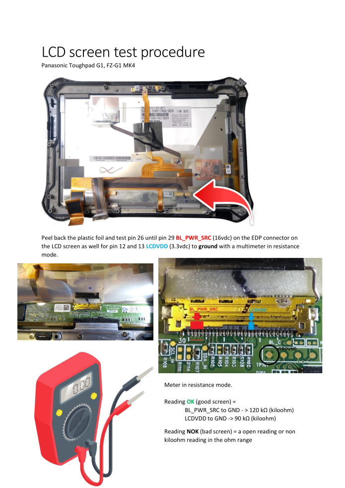
| 14:09, 7 May 2024 | LCD testproc.png (file) |  |
524 KB | Polymorphic7 | 1 | |
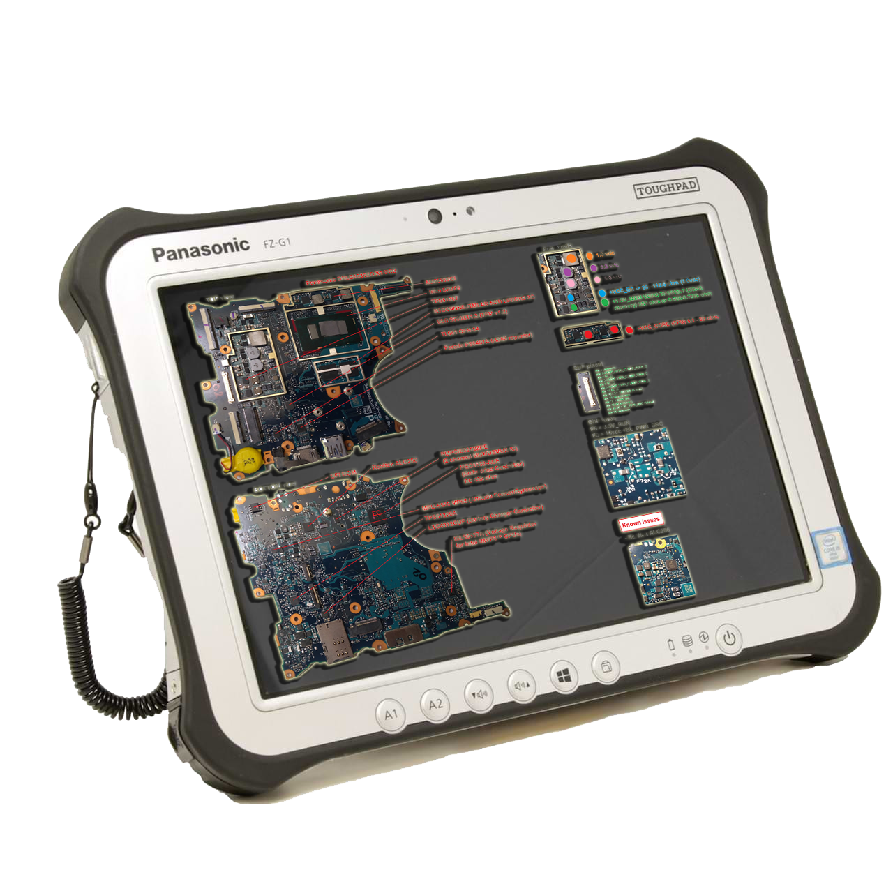
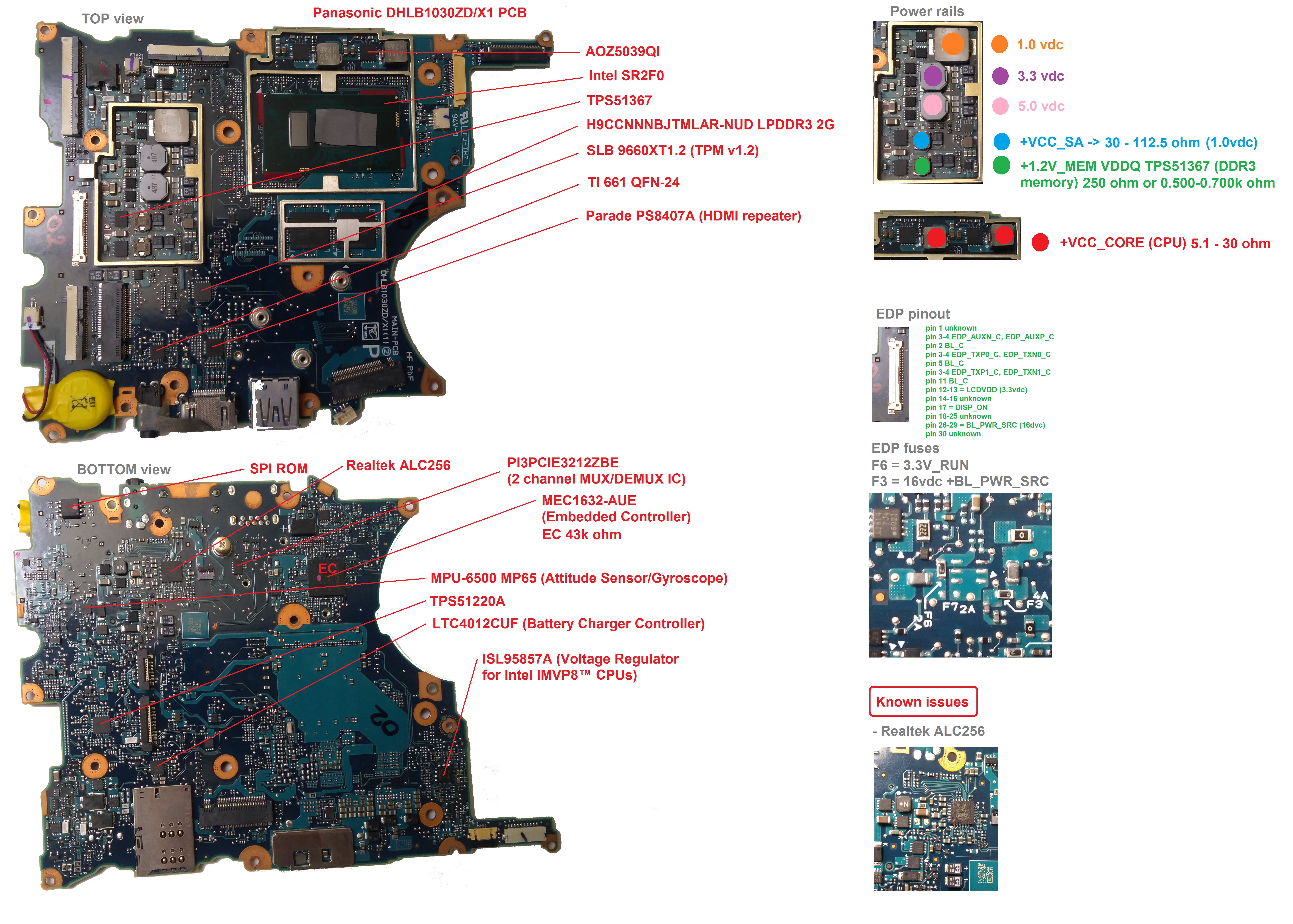
| 14:08, 7 May 2024 | Mb breakdown.jpg (file) |  |
4.12 MB | Polymorphic7 | 1 | |
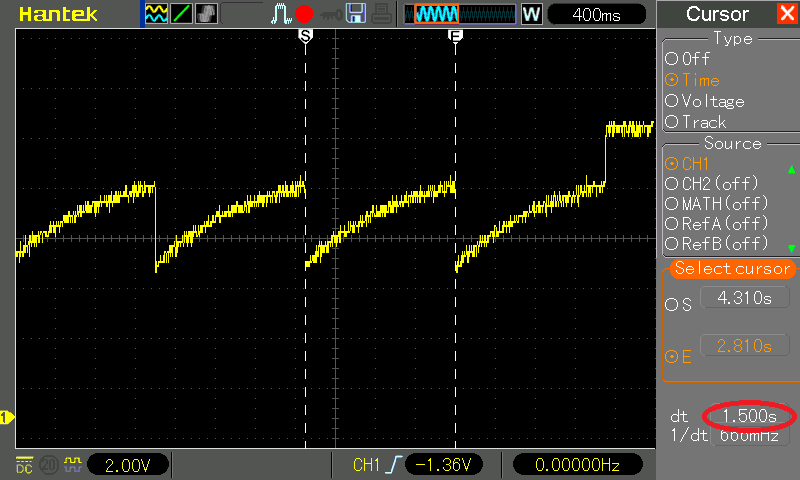
| 06:43, 26 April 2024 | Cdf timer rc scope2.png (file) |  |
17 KB | Trevor229 | Scope view of the RC oscillator on the CD&F Timer | 1 |
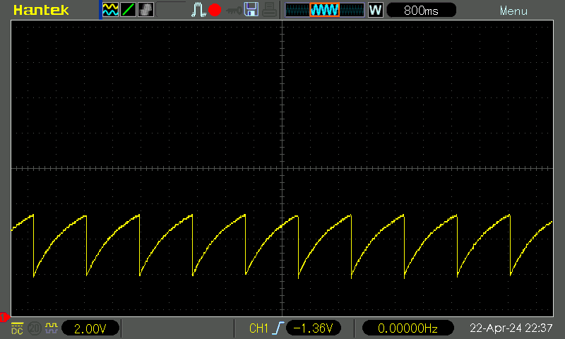
| 06:42, 26 April 2024 | Cdf timer RC scope.png (file) |  |
26 KB | Trevor229 | Scope view of the RC oscillator on the CD&F Timer | 1 |
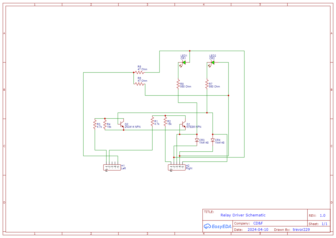
| 00:15, 17 April 2024 | Cdf relay driver schematic.png (file) |  |
53 KB | Trevor229 | (Hopefully correct) schematic of the CD&F relay driver board | 1 |
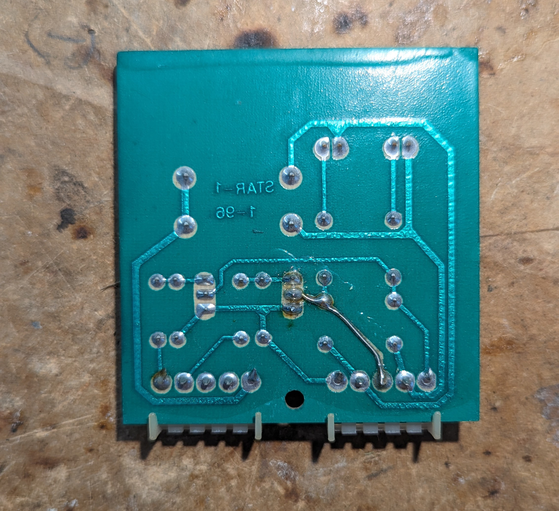
| 00:14, 17 April 2024 | Cdf relay driver back.jpg (file) |  |
1.17 MB | Trevor229 | Backside of the relay driver board for the CD&F | 1 |
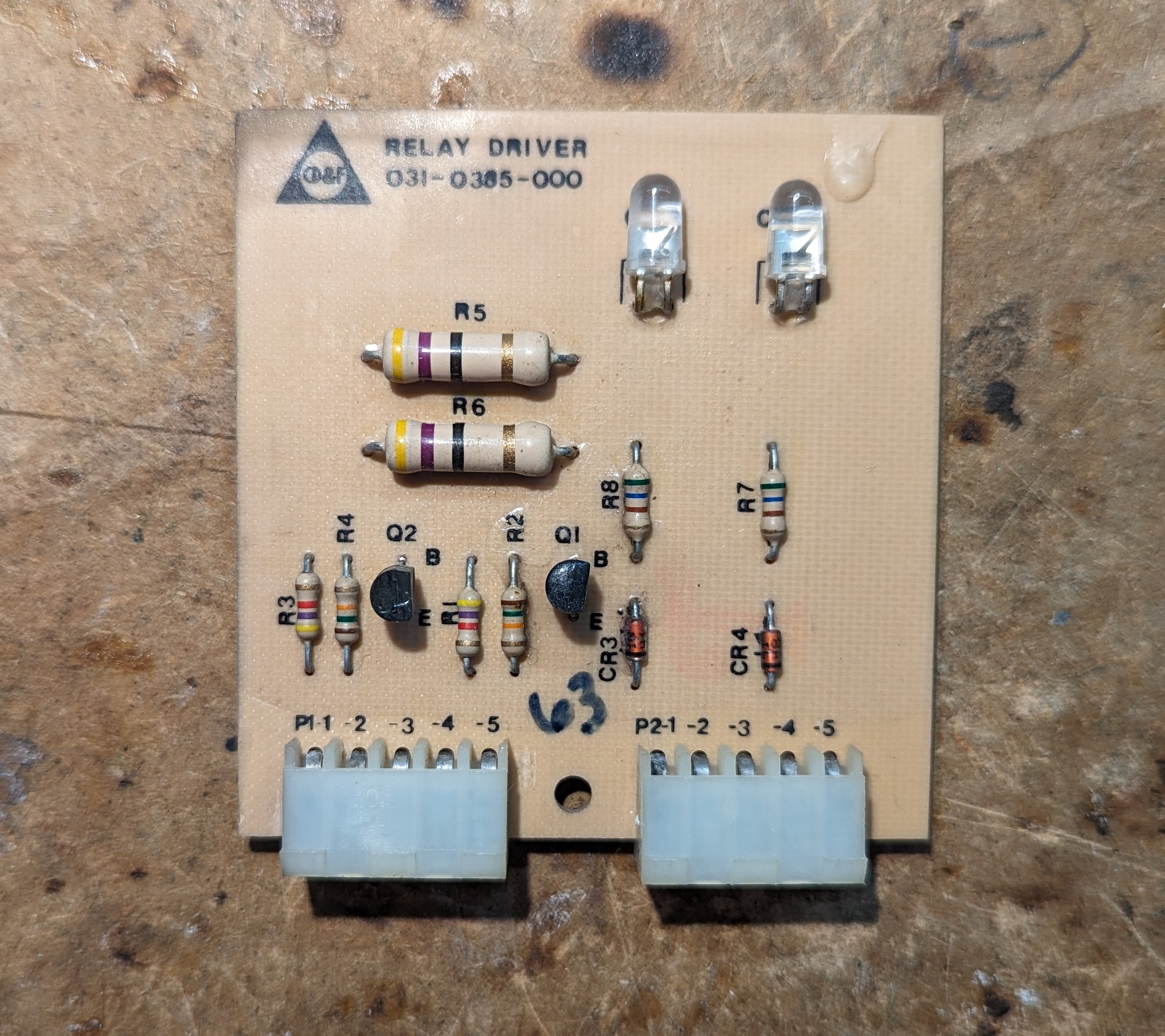
| 00:13, 17 April 2024 | Cdf relay driver top.jpg (file) |  |
1.32 MB | Trevor229 | Relay driver board from the CD&F | 1 |
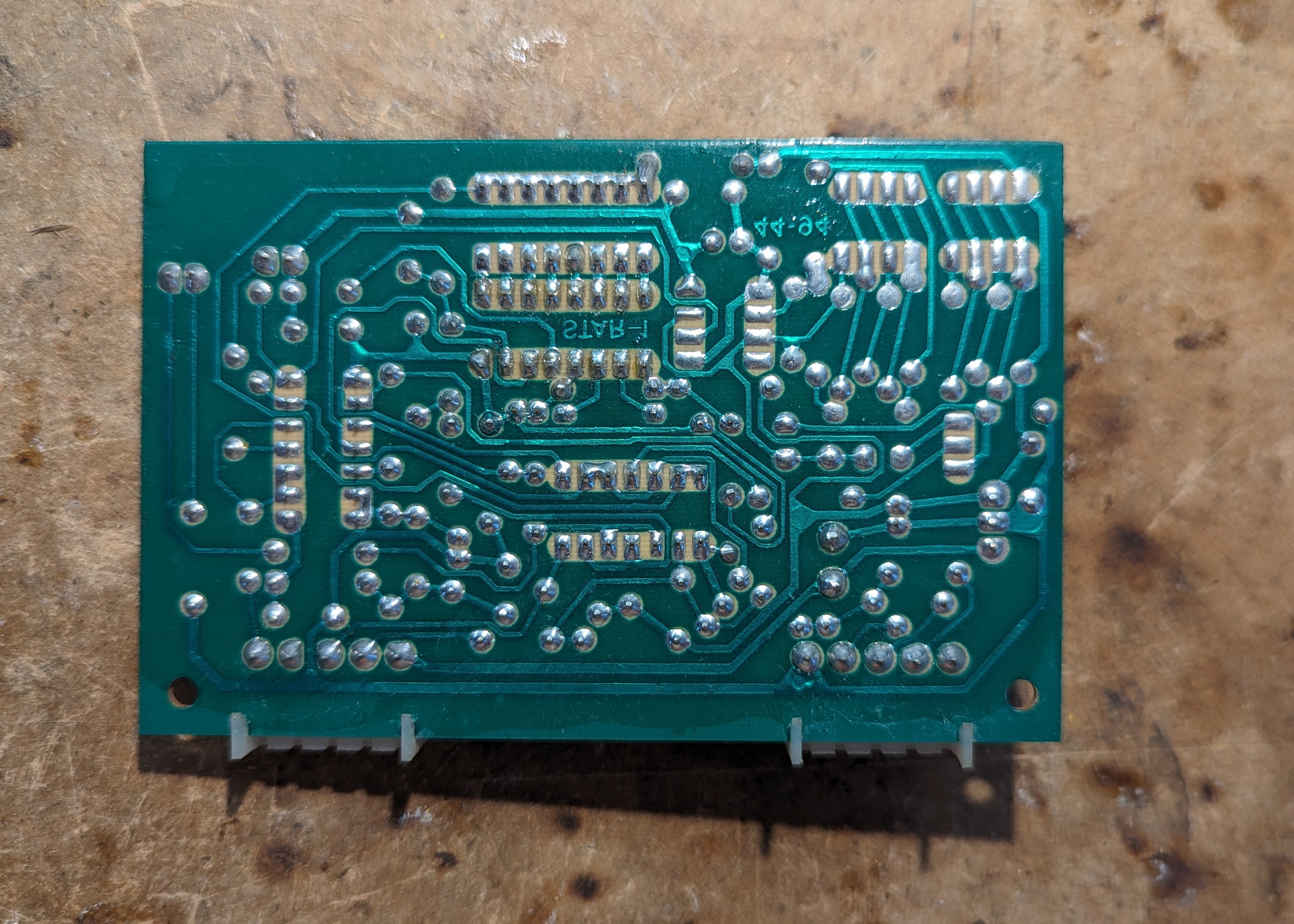
| 00:10, 17 April 2024 | Cdf cycle timer back.jpg (file) |  |
1.91 MB | Trevor229 | Cycle timer (Steady) backside (Mirrored to match Cdf_cycle_timer_front.jpg) | 1 |
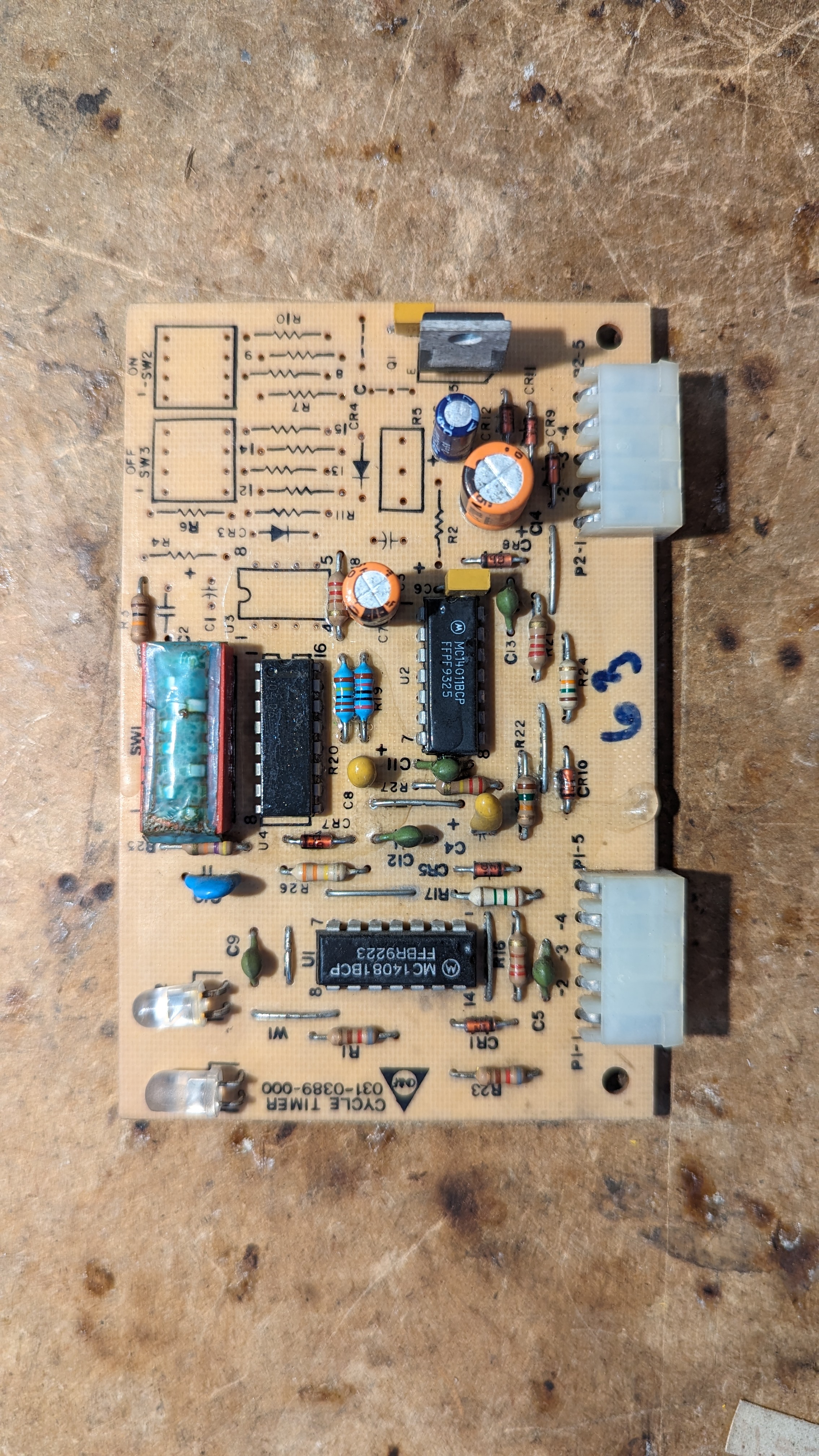
| 00:09, 17 April 2024 | Cdf cycle timer front.jpg (file) |  |
2.58 MB | Trevor229 | Cycle timer (Steady) front from the CD&F | 1 |
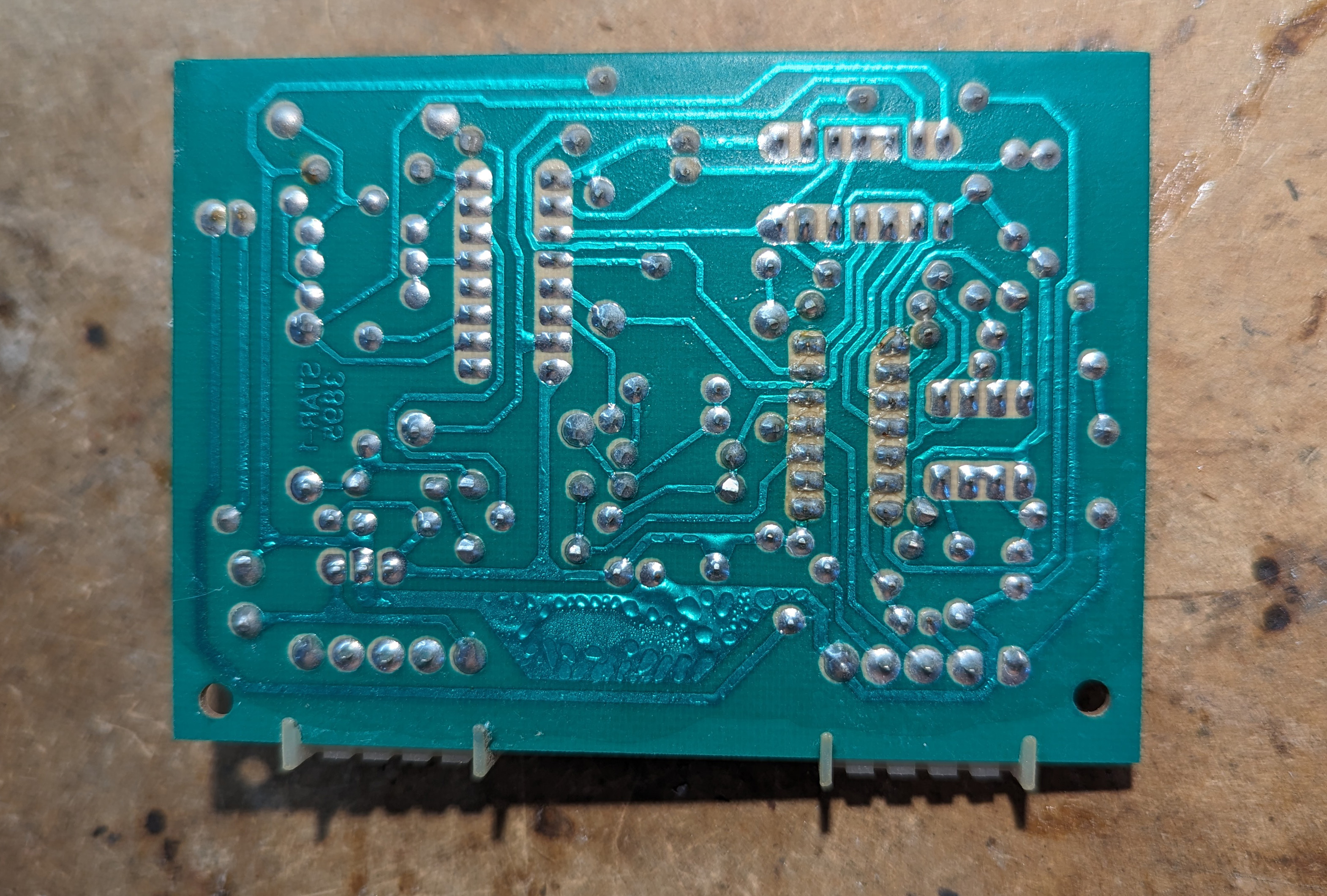
| 00:09, 17 April 2024 | Cdf decoder module a back.jpg (file) |  |
1.67 MB | Trevor229 | Backside of the tone decoder module from the CD&F (Mirrored to match Cdf_decoder_module_a_front.jpg | 1 |
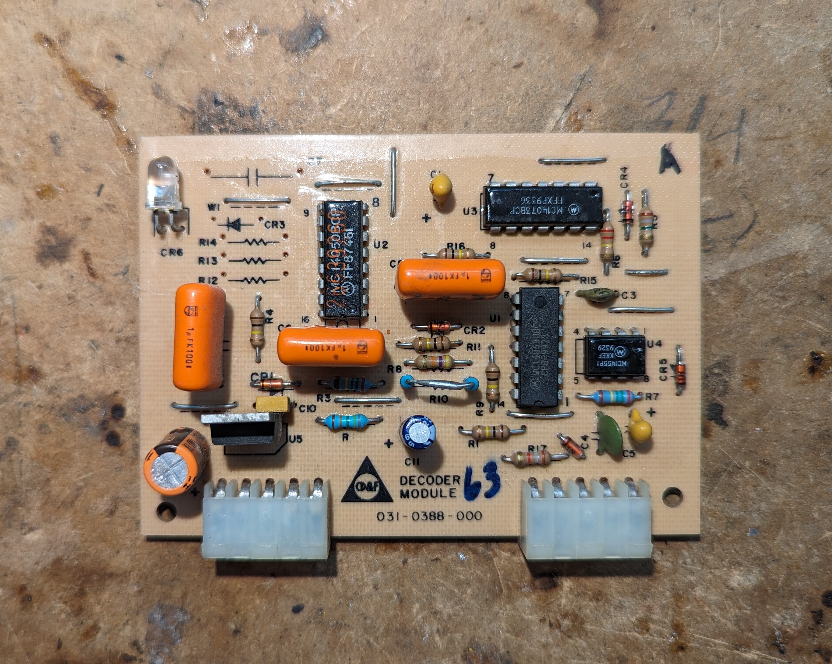
| 00:07, 17 April 2024 | Cdf decoder module a front.jpg (file) |  |
1.94 MB | Trevor229 | Front of the tone decoder module from the CD&F | 1 |
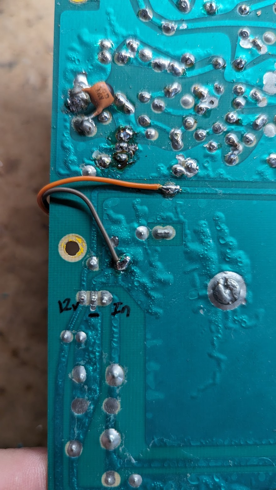
| 03:25, 16 April 2024 | Cdf mod power connections.jpg (file) |  |
364 KB | Trevor229 | Connections for Vin and GND to power the arduino and Si5351 board on the CD&F. Pulling power from the main 12v regulator | 1 |
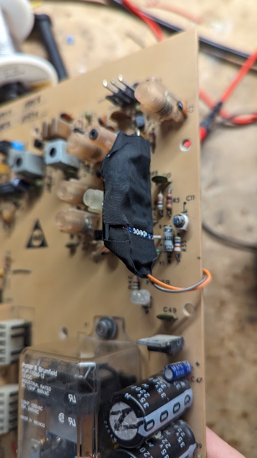
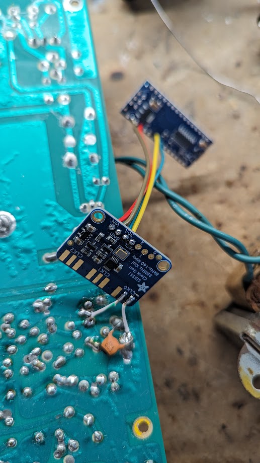
| 03:24, 16 April 2024 | Cdf modded LO.jpg (file) |  |
98 KB | Trevor229 | Final mod showing the insulated arduino and Si5351 board attached to the CD&F main board | 1 |
| 03:21, 16 April 2024 | Cdf si5351 test.jpg (file) |  |
123 KB | Trevor229 | Test setup of the Si5351 breakout board to replace the LO crystal on the CD&F | 1 |
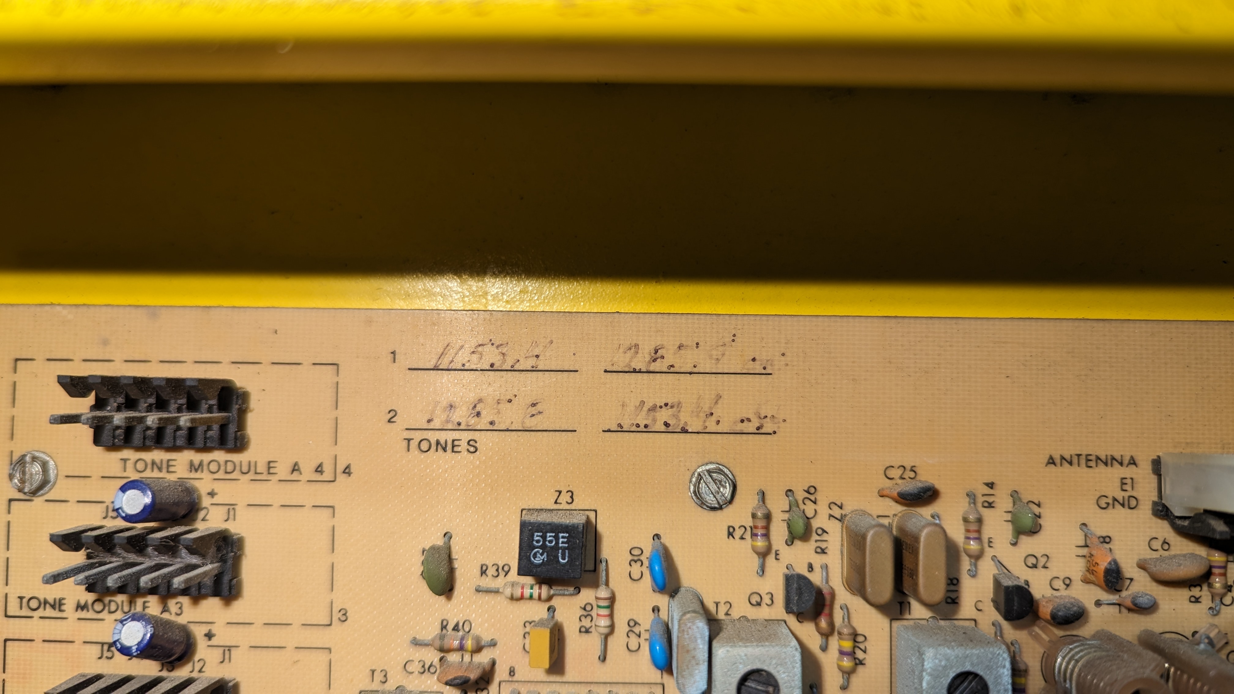
| 23:26, 15 April 2024 | Cdf tone info.jpg (file) |  |
1.46 MB | Trevor229 | Configured tone information handwritten on the CD&F main board near the top center. Sequence 1 is to activate, sequence 2 is to deactivate. | 1 |
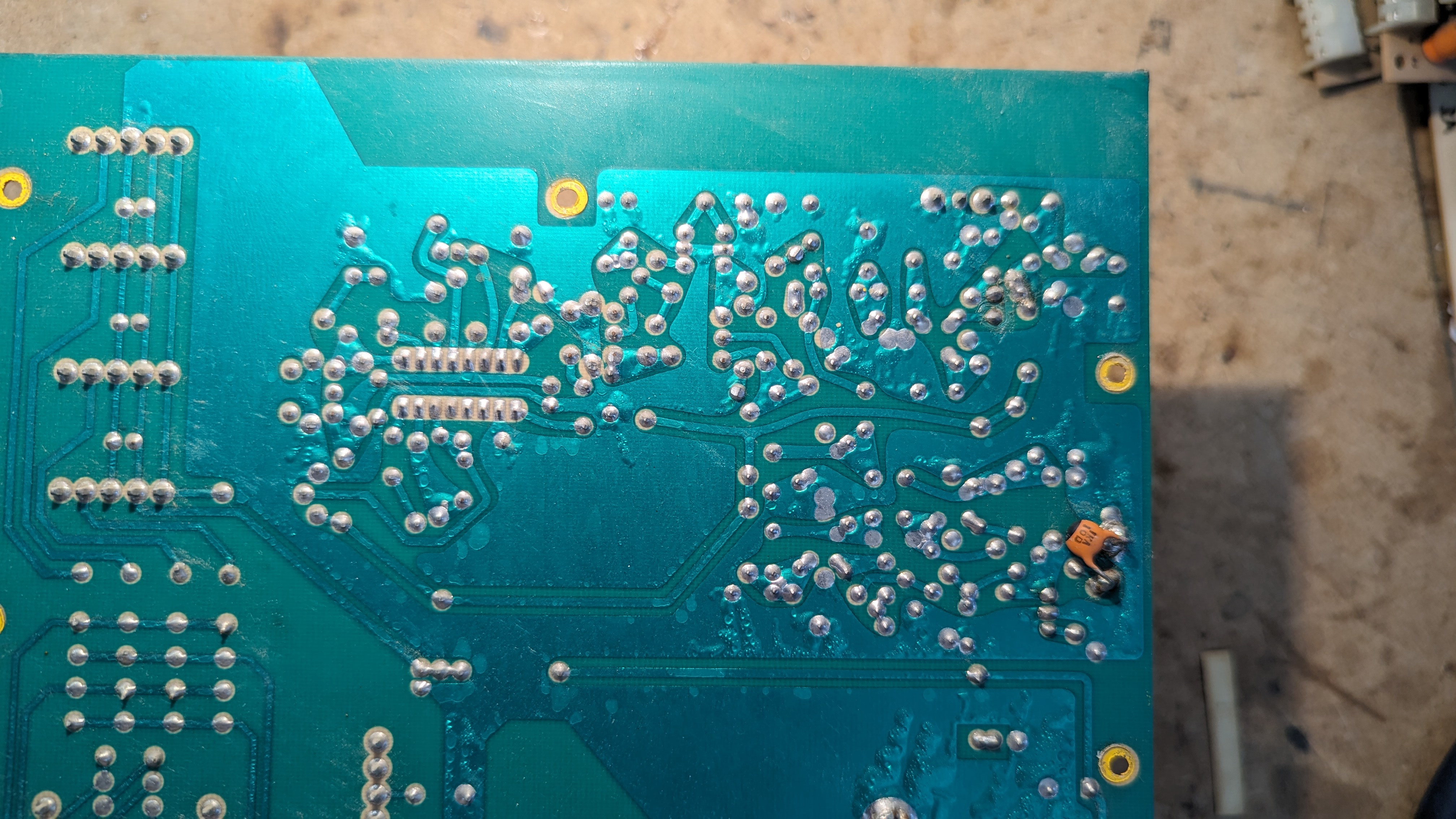
| 23:23, 15 April 2024 | Cdf rx closeup back.jpg (file) |  |
2.15 MB | Trevor229 | Closeup of the rear of the double conversion super heterodyne radio receiver circuitry in the CD&F. Mirrored to match Cdf_rx_closeup.jpg | 1 |
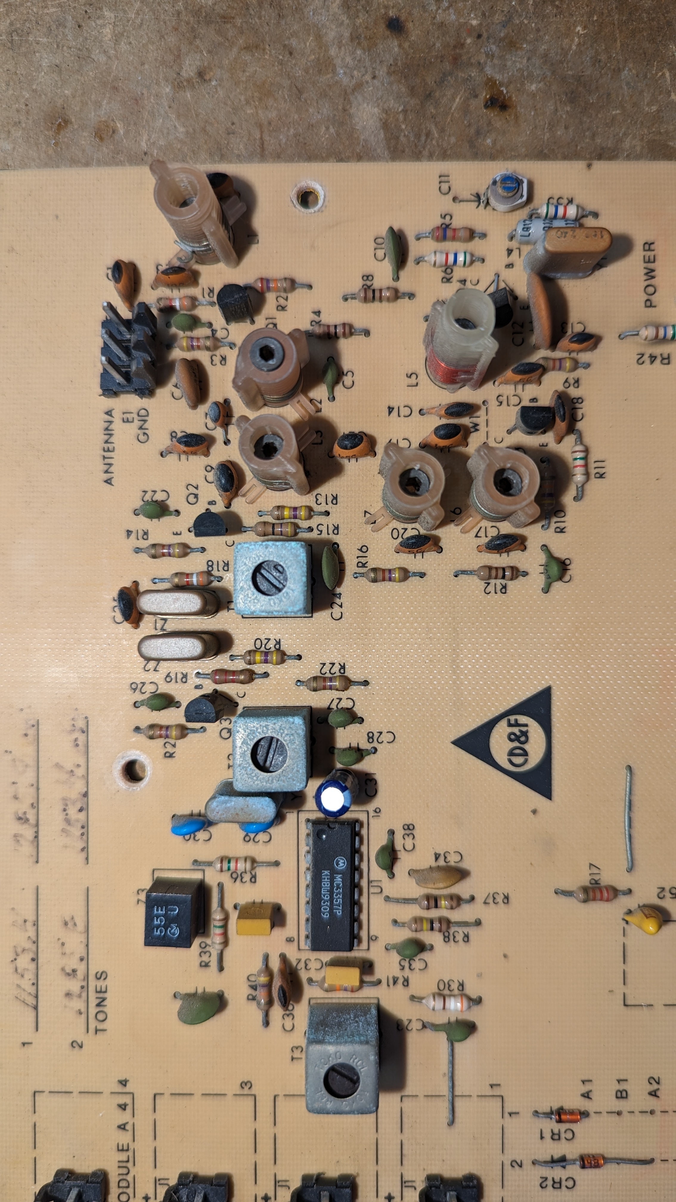
| 23:22, 15 April 2024 | Cdf rx closeup.jpg (file) |  |
1.94 MB | Trevor229 | Closeup of the double conversion super heterodyne radio receiver circuitry in the CD&F | 1 |
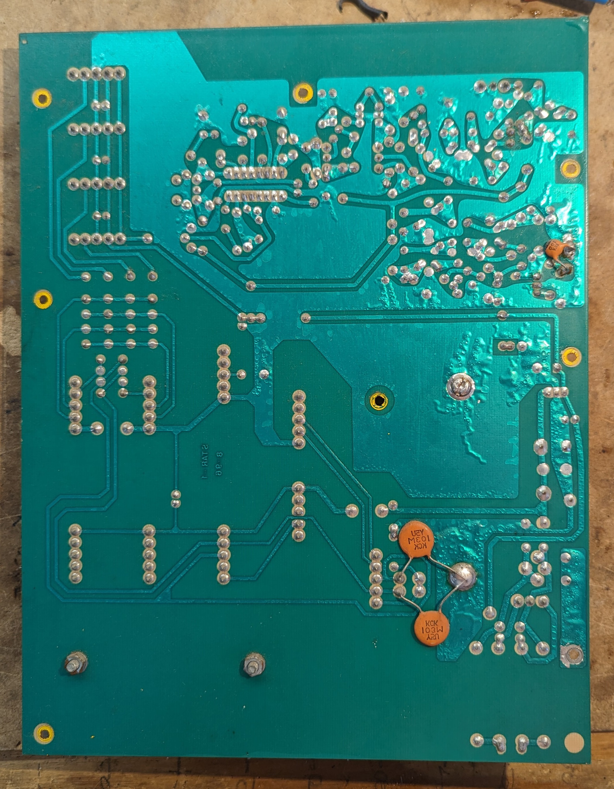
| 23:21, 15 April 2024 | Cdf bare mainboard back.jpg (file) |  |
1.48 MB | Trevor229 | Flipped horizontally to match Cdf_bare_mainboard.jpg | 2 |
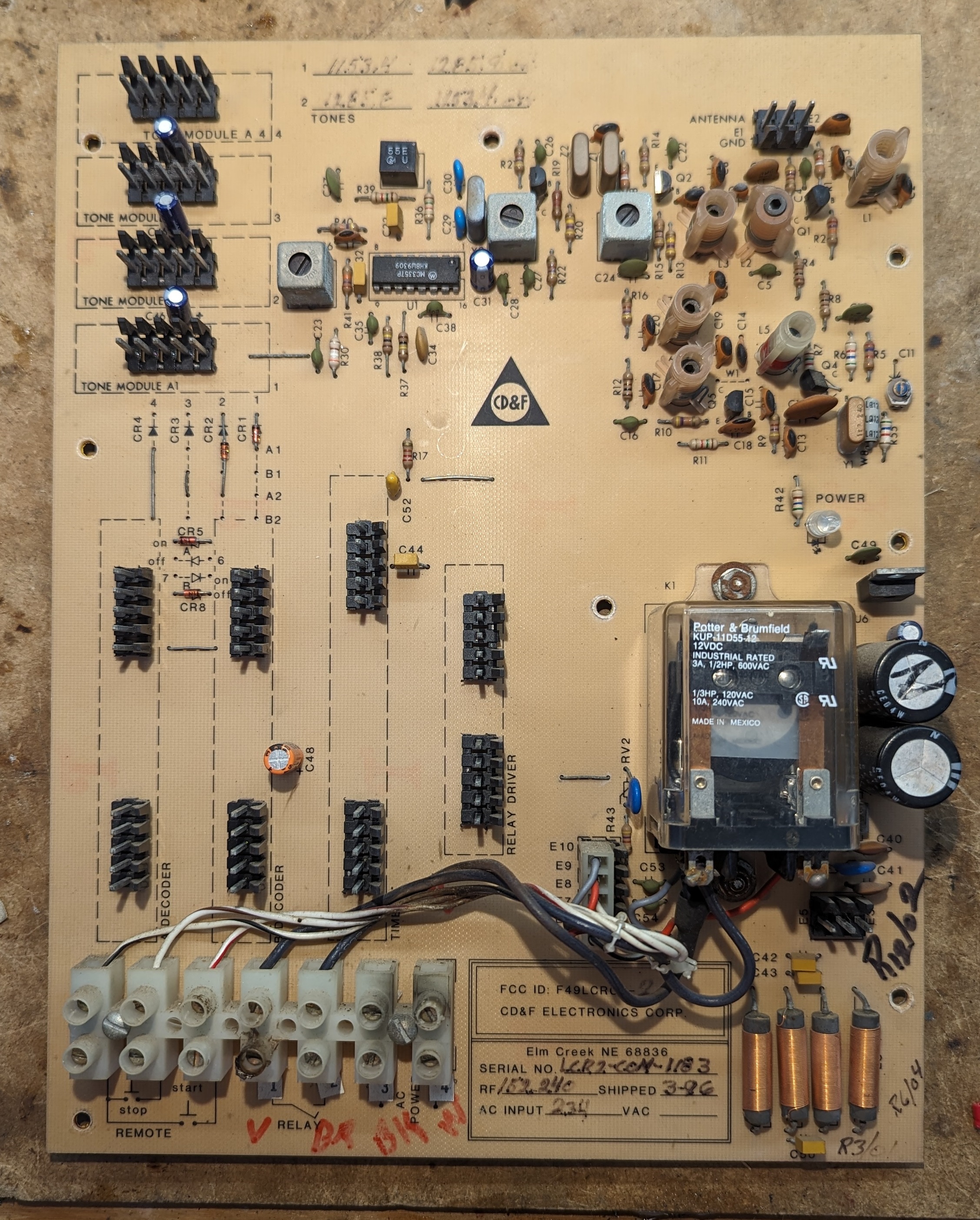
| 23:16, 15 April 2024 | Cdf bare mainboard.jpg (file) |  |
1.96 MB | Trevor229 | Bare mainboard of the CD&F. All cards removed for visibility. | 1 |
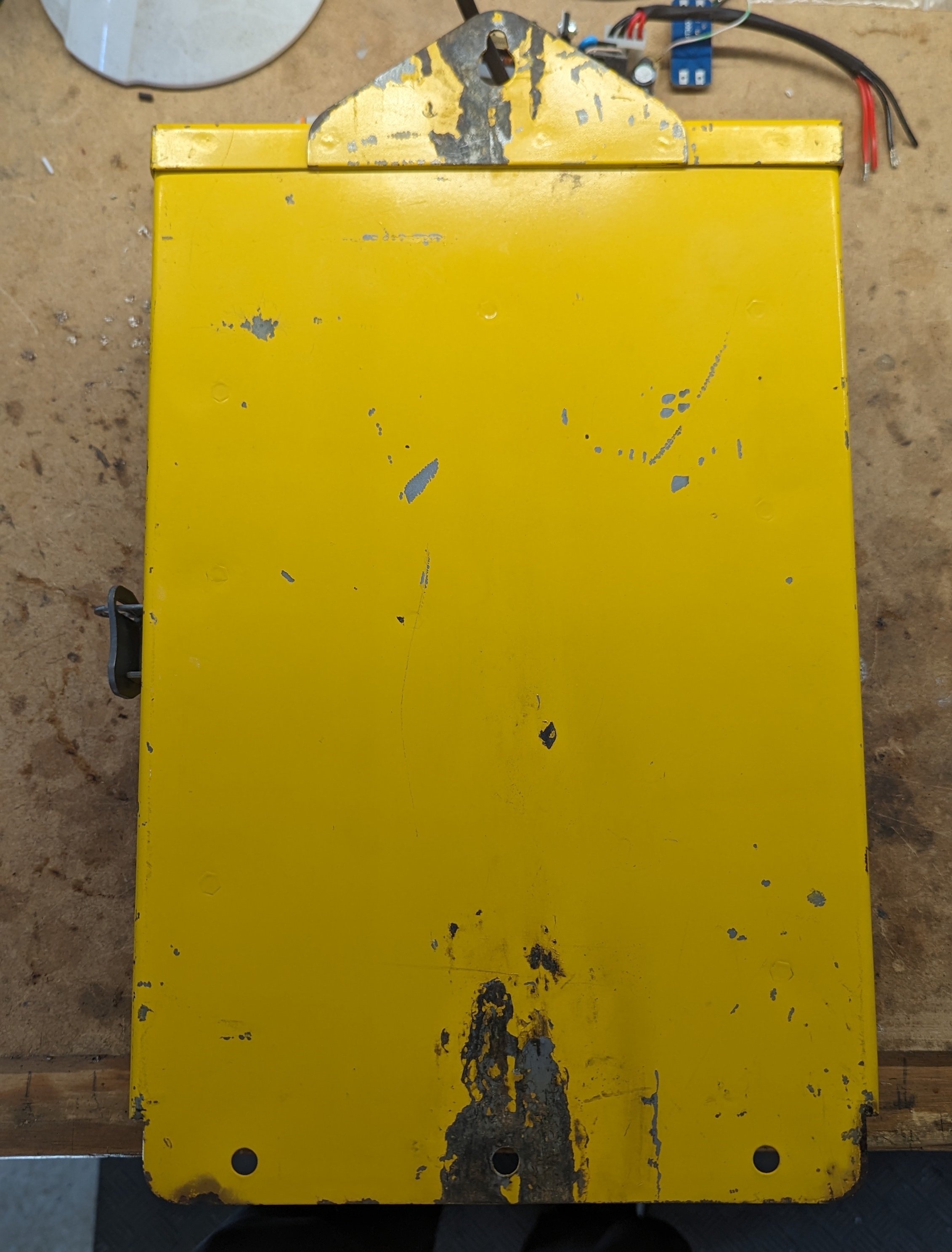
| 23:14, 15 April 2024 | Cdf back.jpg (file) |  |
1,002 KB | Trevor229 | Back of the enclosure, showing the integrated mounting holes. | 1 |
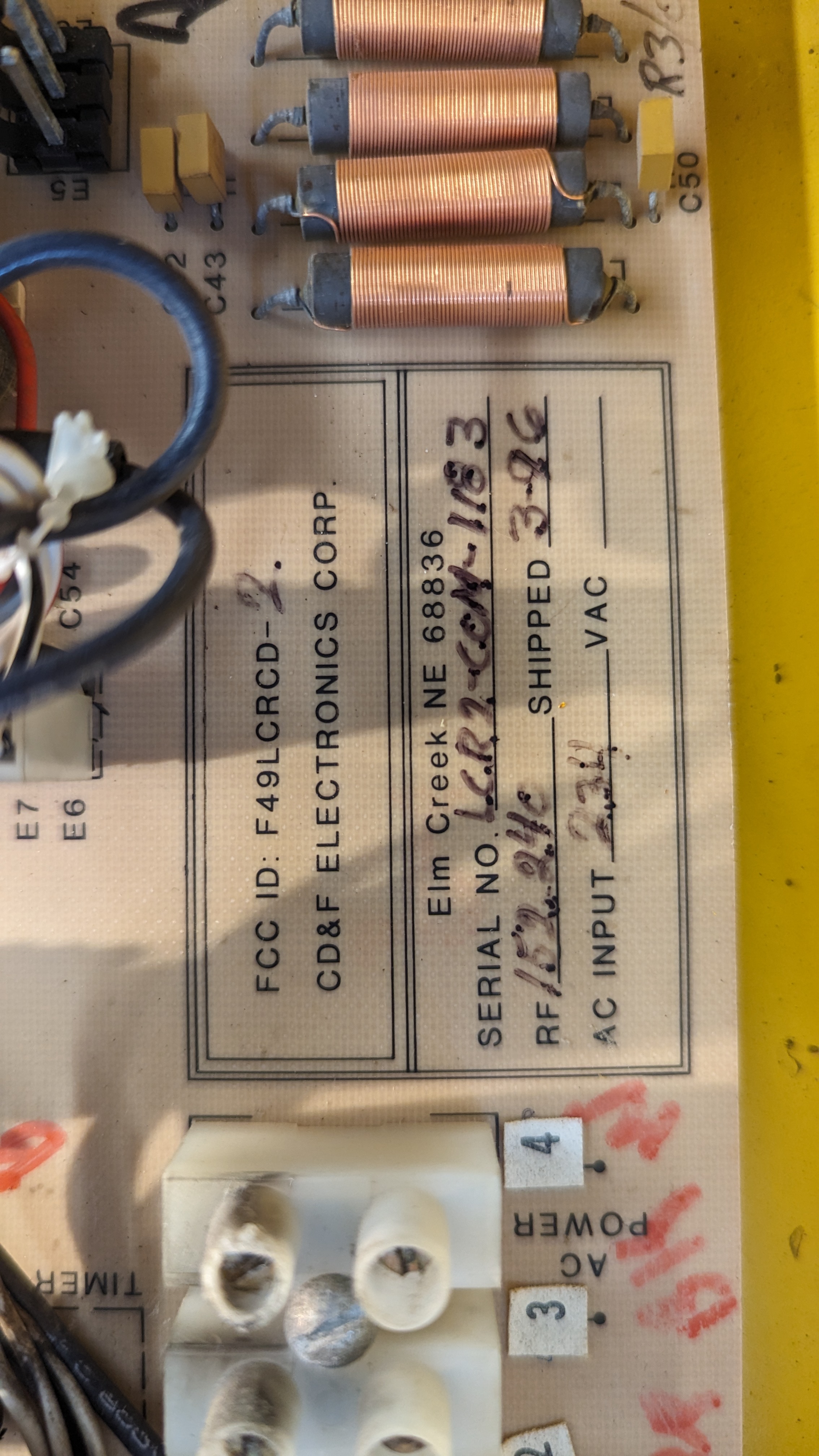
| 23:13, 15 April 2024 | Cdf info onboard.jpg (file) |  |
1.79 MB | Trevor229 | Info written near the bottom center of the mainboard. Shows FCC-ID, serial, receive frequency, input voltage, and ship date. | 1 |
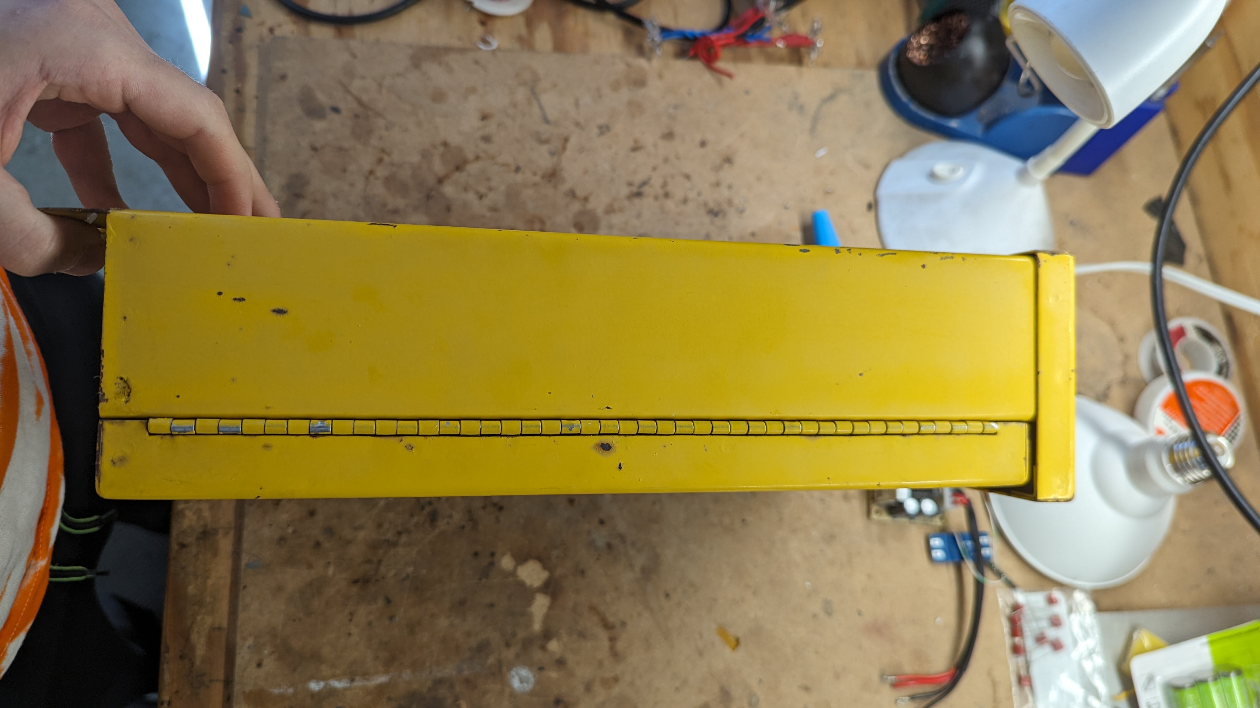
| 23:11, 15 April 2024 | Cdf hinge side.jpg (file) |  |
1.24 MB | Trevor229 | Side of the enclosure with the hinge. The hinge cannot be removed from the door, but the door and hinge can be removed from the enclosure with three screws and nuts. | 1 |
| 23:10, 15 April 2024 | Cdf latch side.jpg (file) |  |
1.2 MB | Trevor229 | Side of the enclosure with latch. First flips out, then rotate the wing to loosen the clamp. | 1 |
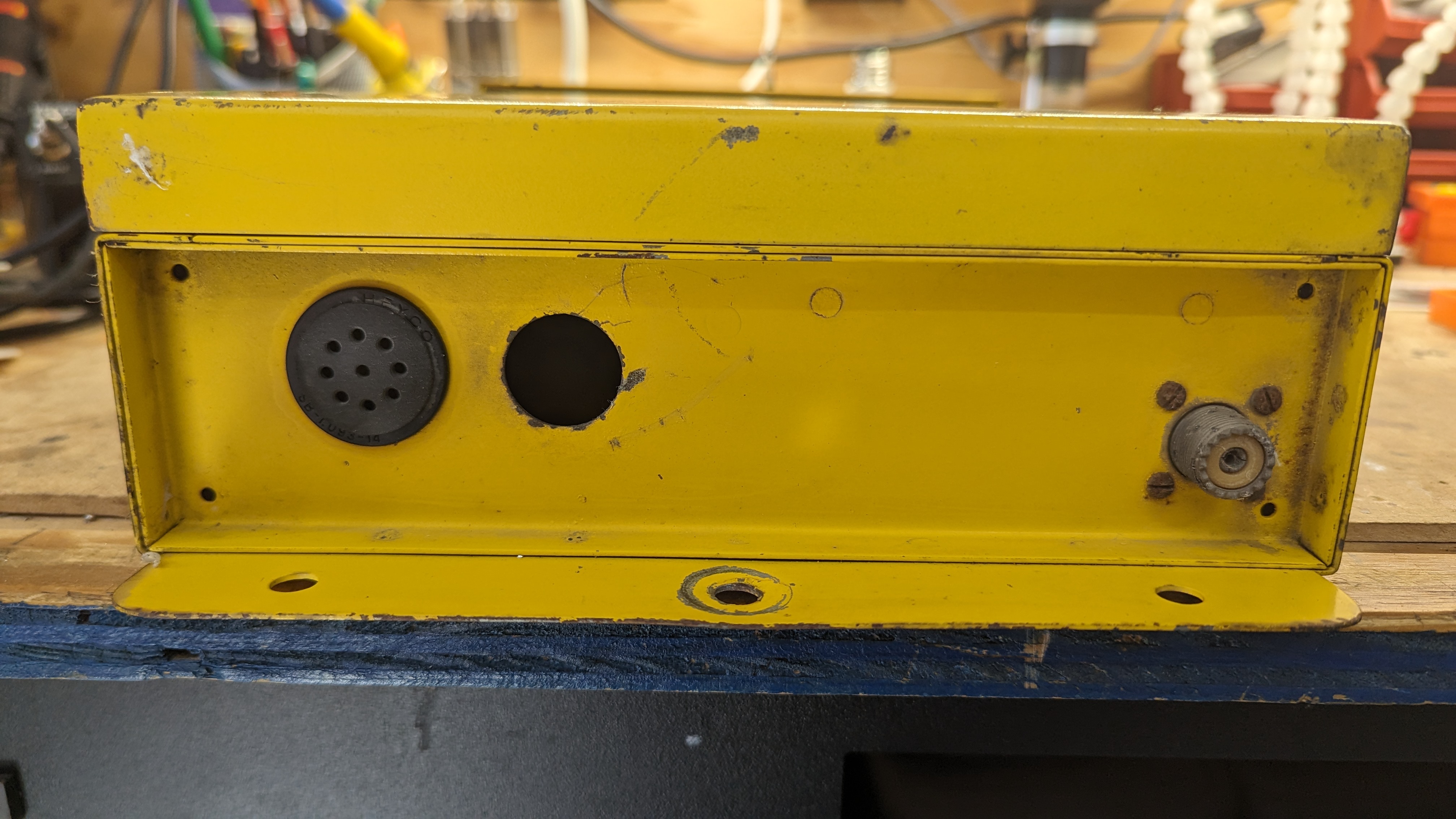
| 23:07, 15 April 2024 | Cdf bottom.jpg (file) |  |
1.68 MB | Trevor229 | Bottom of the CD&F housing showing the conduit and vent holes as well as an unused SO-239 connector for replacing the whip antenna. | 1 |
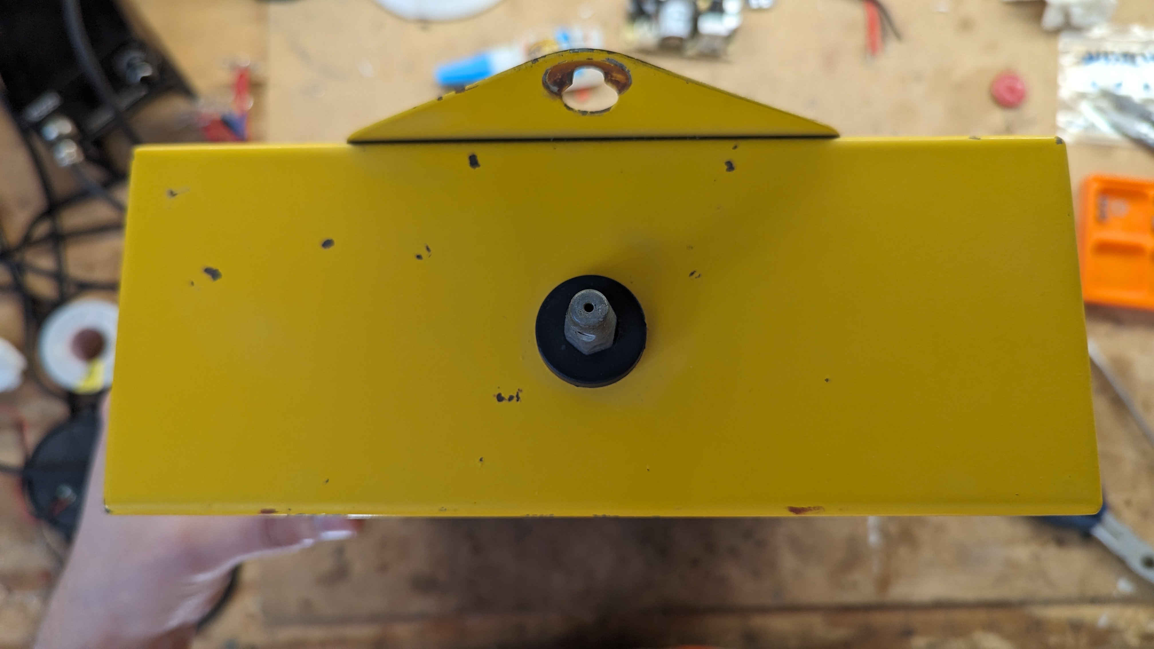
| 23:04, 15 April 2024 | Cdf top.jpg (file) |  |
1.18 MB | Trevor229 | Top of the CD&F housing showing the antenna mount without the antenna | 1 |
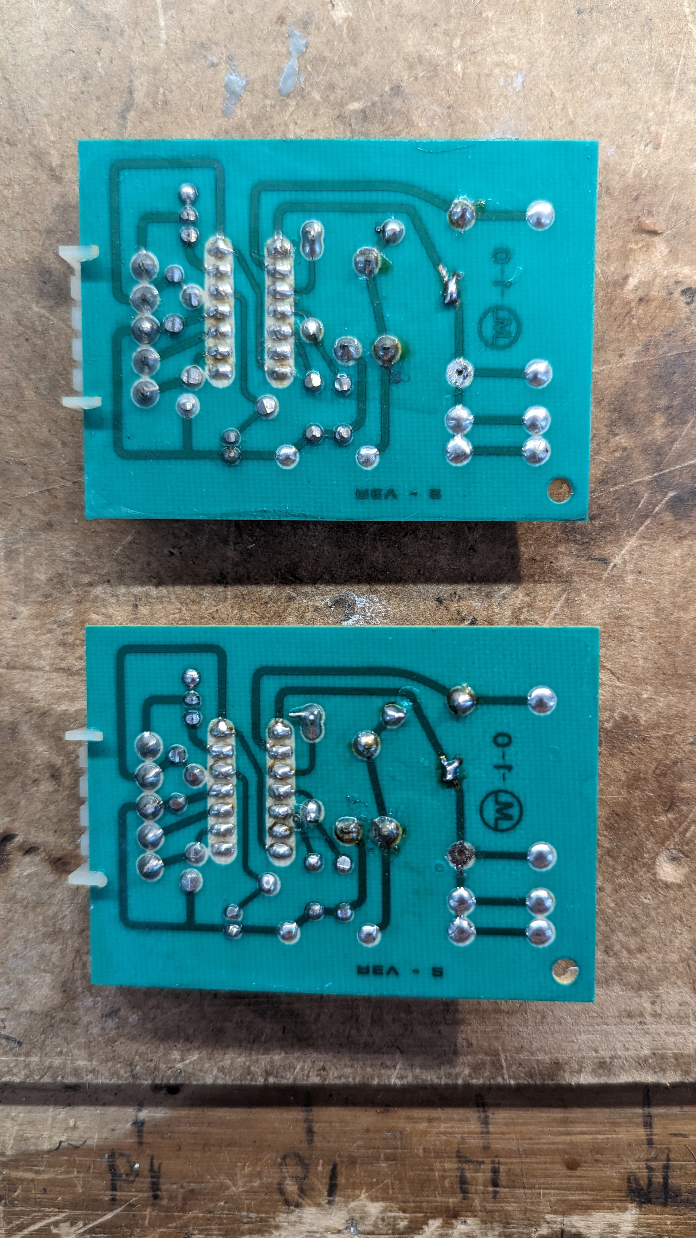
| 23:03, 15 April 2024 | Cdf filters bottom.jpg (file) |  |
2.29 MB | Trevor229 | Bottom side of the CD&F tone filter modules. Mirrored to match the top side. | 1 |
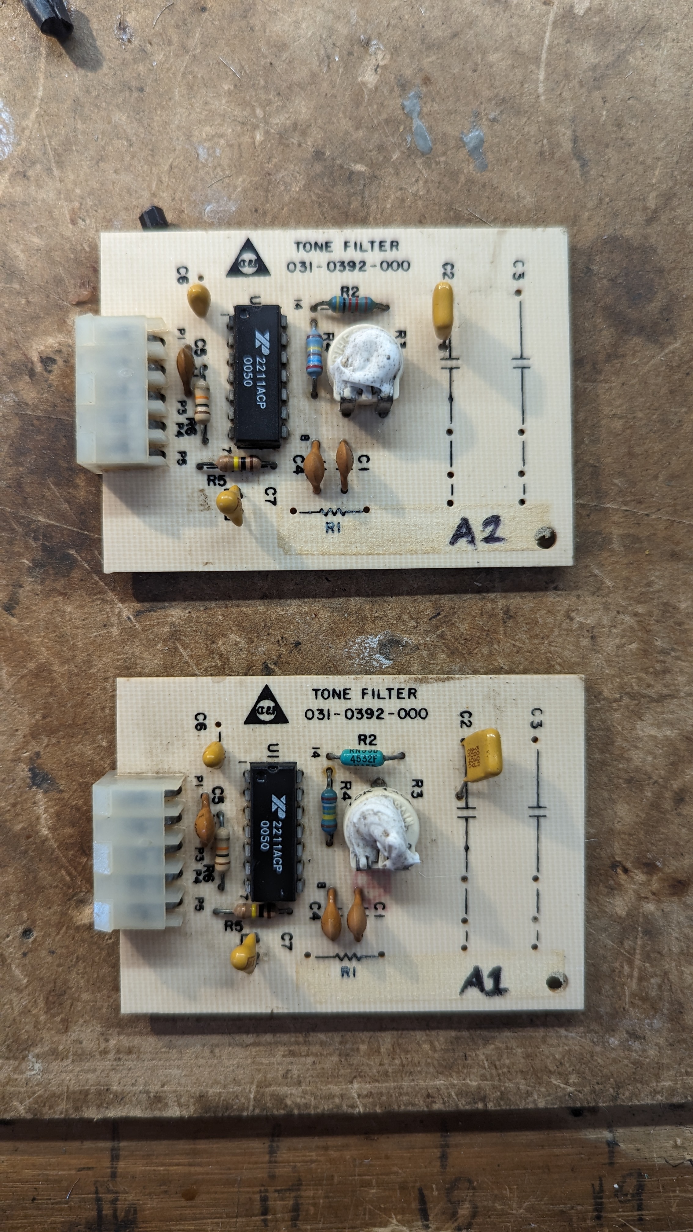
| 23:02, 15 April 2024 | Cdf filters top.jpg (file) |  |
2.31 MB | Trevor229 | Top view of both CD&F tone decoder modules | 1 |
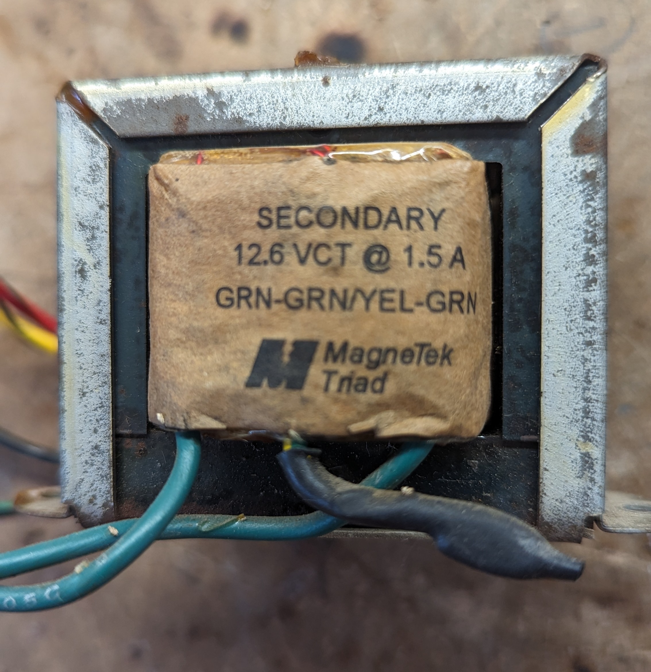
| 06:13, 15 April 2024 | Cdf xfmr sec.jpg (file) |  |
1.3 MB | Trevor229 | Secondary of the CD&F transformer | 1 |
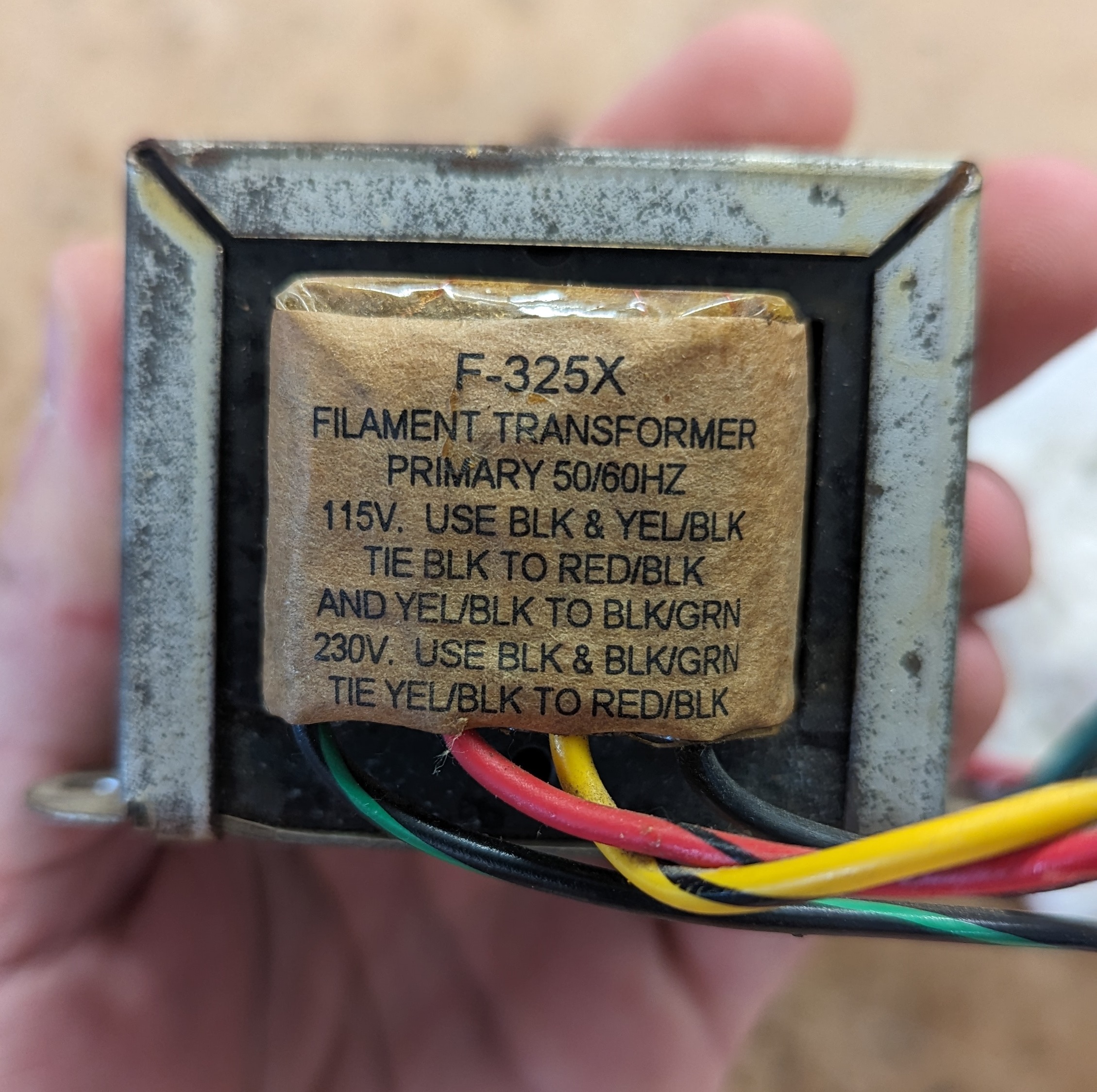
| 06:13, 15 April 2024 | Cdf xfmr pri.jpg (file) |  |
1.18 MB | Trevor229 | Cropped to fit better | 2 |
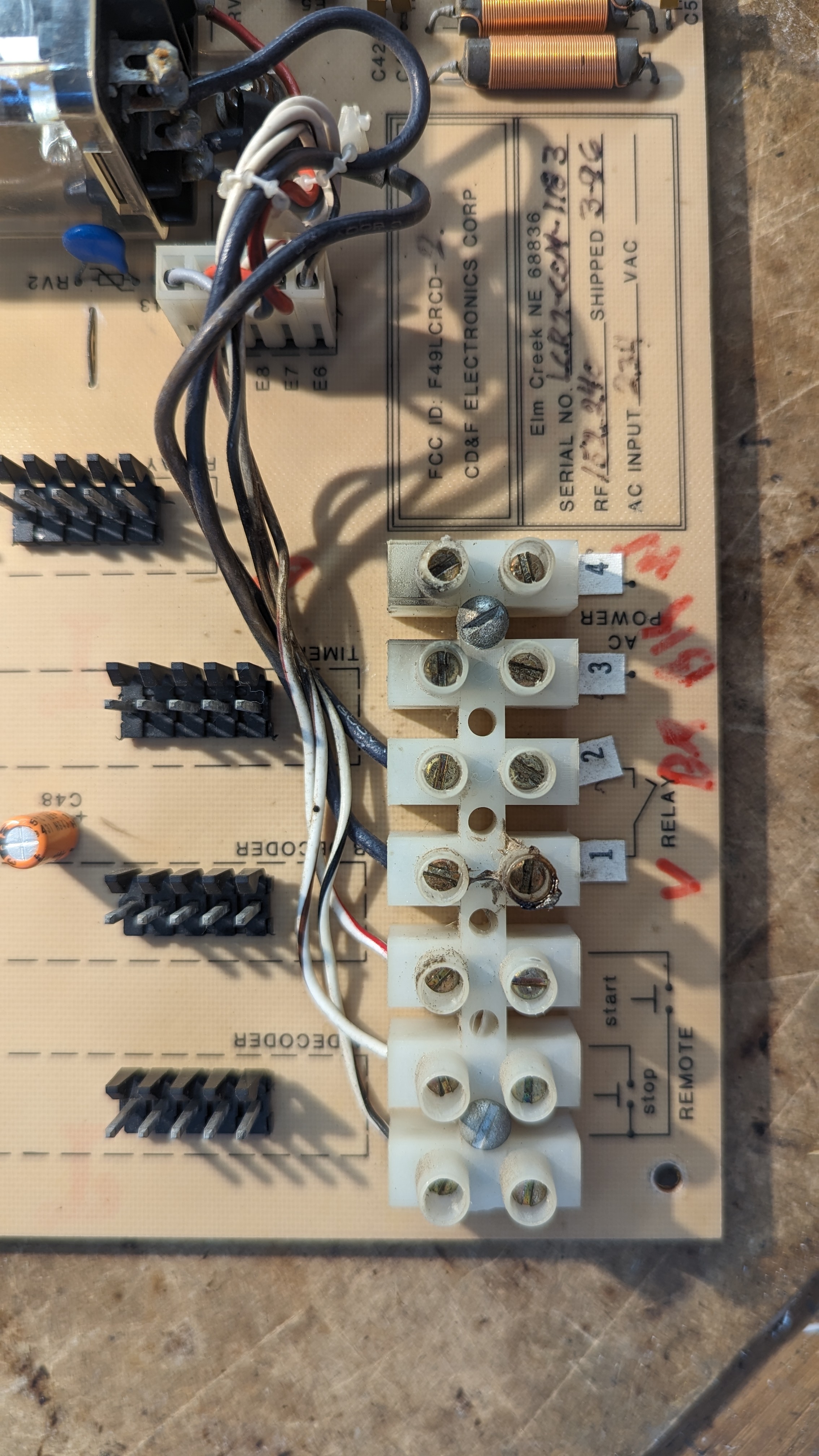
| 06:05, 15 April 2024 | Cdf terminals closeup.jpg (file) |  |
1.62 MB | Trevor229 | Closeup of the terminal block on the CD&F controller | 1 |
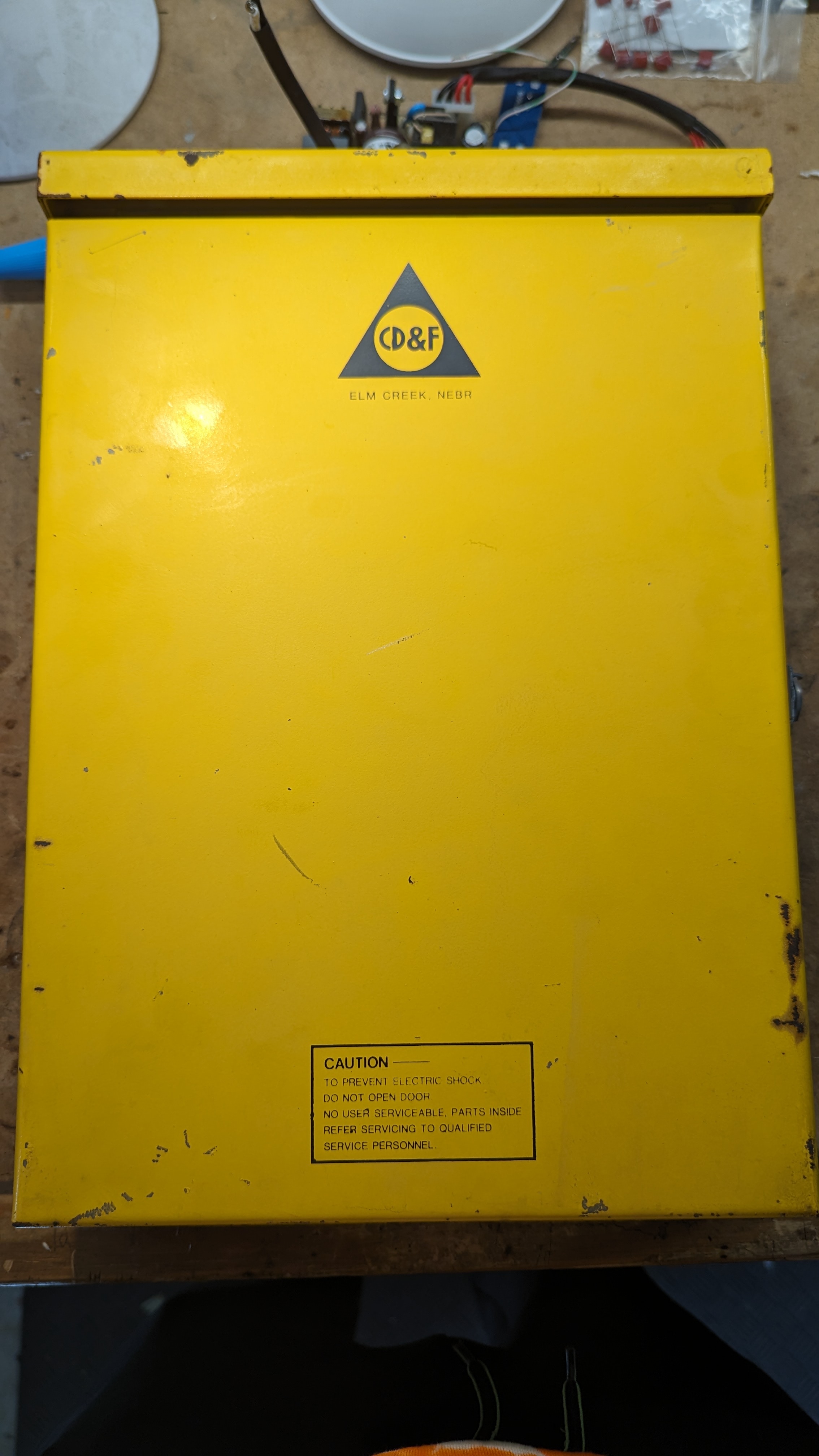
| 05:46, 15 April 2024 | Cdf front closed.jpg (file) |  |
1.03 MB | Trevor229 | CD&F with the front door closed | 1 |
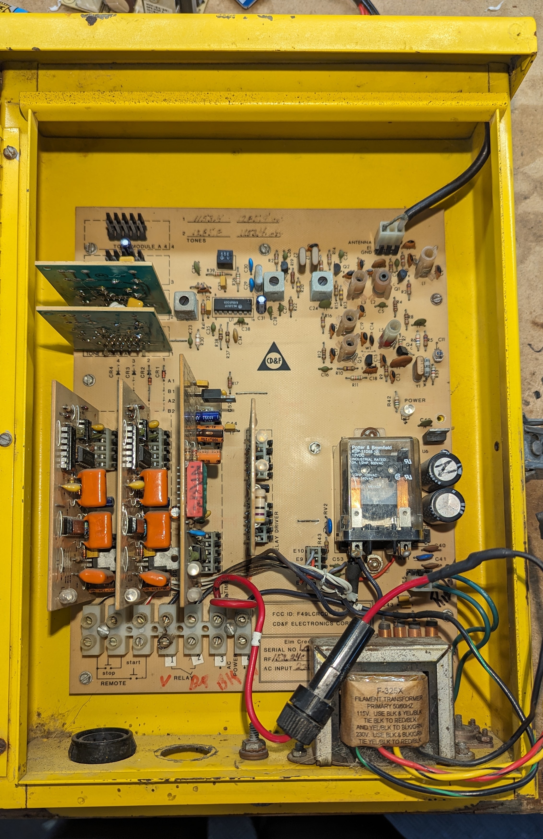
| 05:42, 15 April 2024 | Cdf front open.jpg (file) |  |
2.28 MB | Trevor229 | CD&F controller with the front door open | 1 |
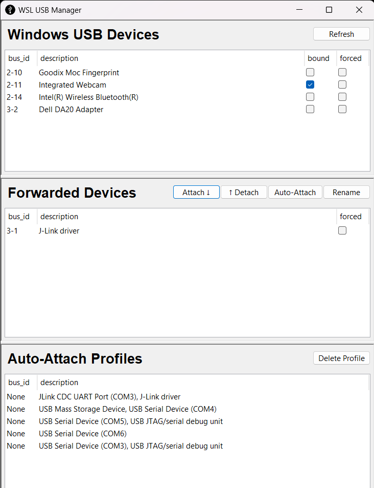
| 20:01, 14 April 2024 | WSL USB GUI Manager.png (file) |  |
36 KB | Hash | 1 | |
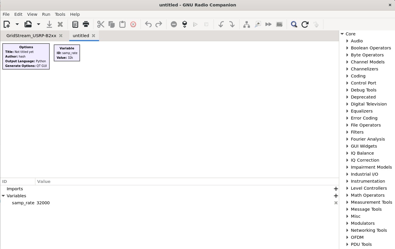
| 16:07, 14 April 2024 | Grc on wsl.jpg (file) |  |
123 KB | Hash | 1 | |
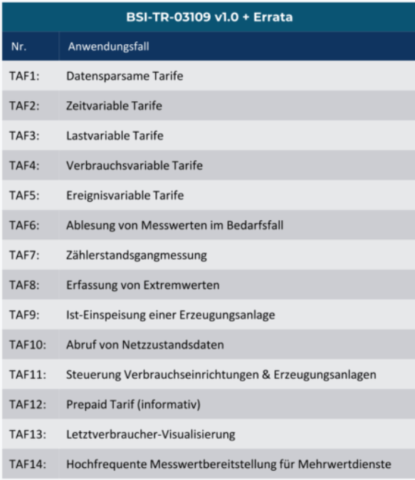
| 10:50, 10 March 2024 | TAF.png (file) |  |
120 KB | Barney | 1 | |
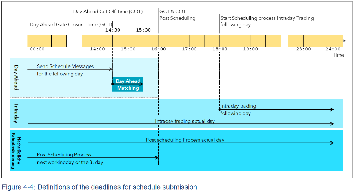
| 15:47, 9 March 2024 | ESS Schedule.png (file) |  |
109 KB | Barney | 1 | |
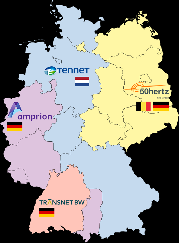
| 15:27, 9 March 2024 | TransmissionGridOperatorsGER.png (file) | 89 KB | Barney | 1 | ||
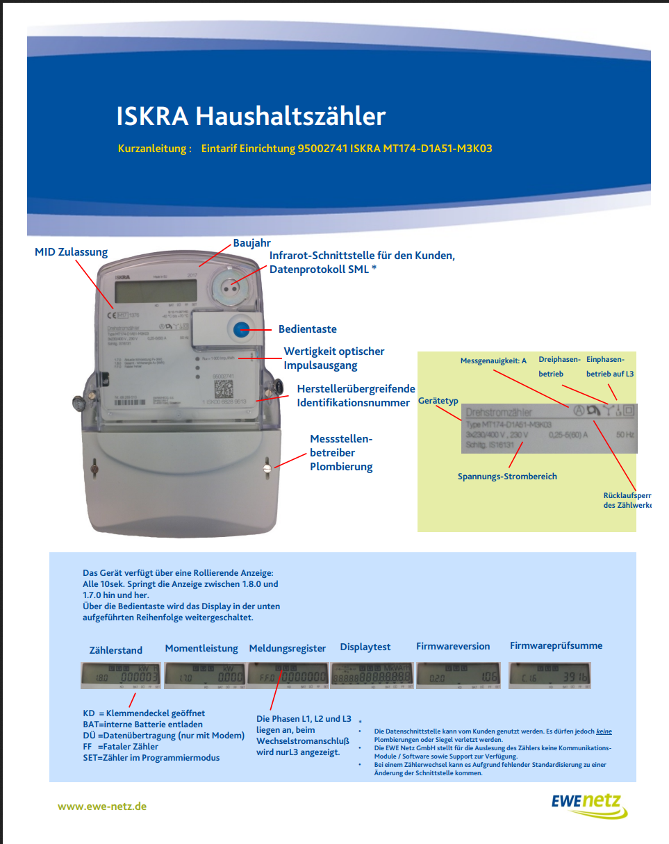
| 21:12, 8 March 2024 | ISKRAMT174.png (file) |  |
541 KB | Barney | 1 | |
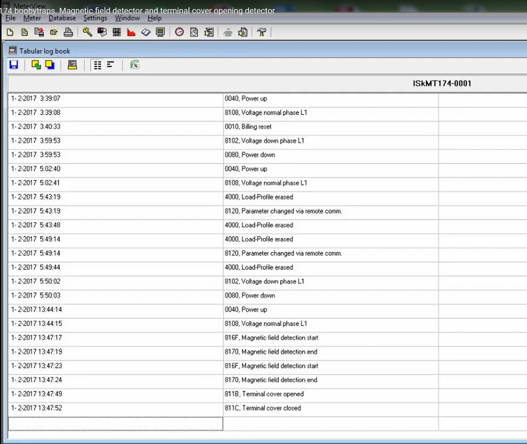
| 21:09, 8 March 2024 | ISKRA LOG.png (file) |  |
941 KB | Barney | 1 | |
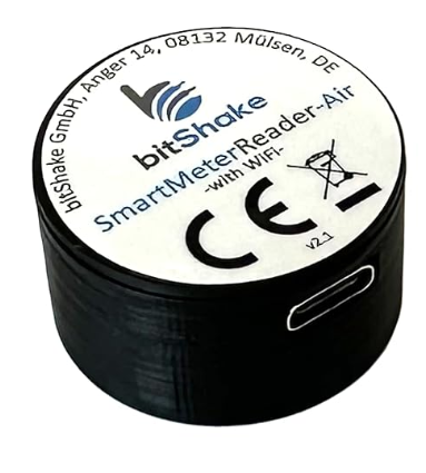
| 11:16, 8 March 2024 | SM reader writer.png (file) |  |
131 KB | Barney | 1 | |
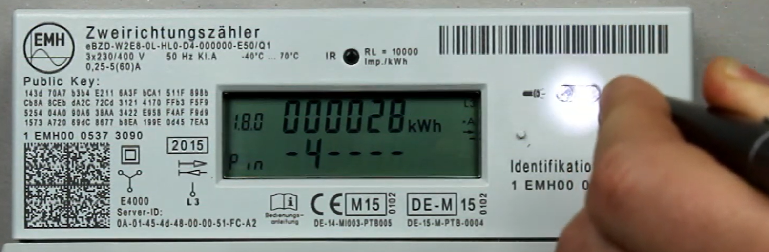
| 10:58, 8 March 2024 | FlashlightPIN.png (file) |  |
1.25 MB | Barney | 1 | |
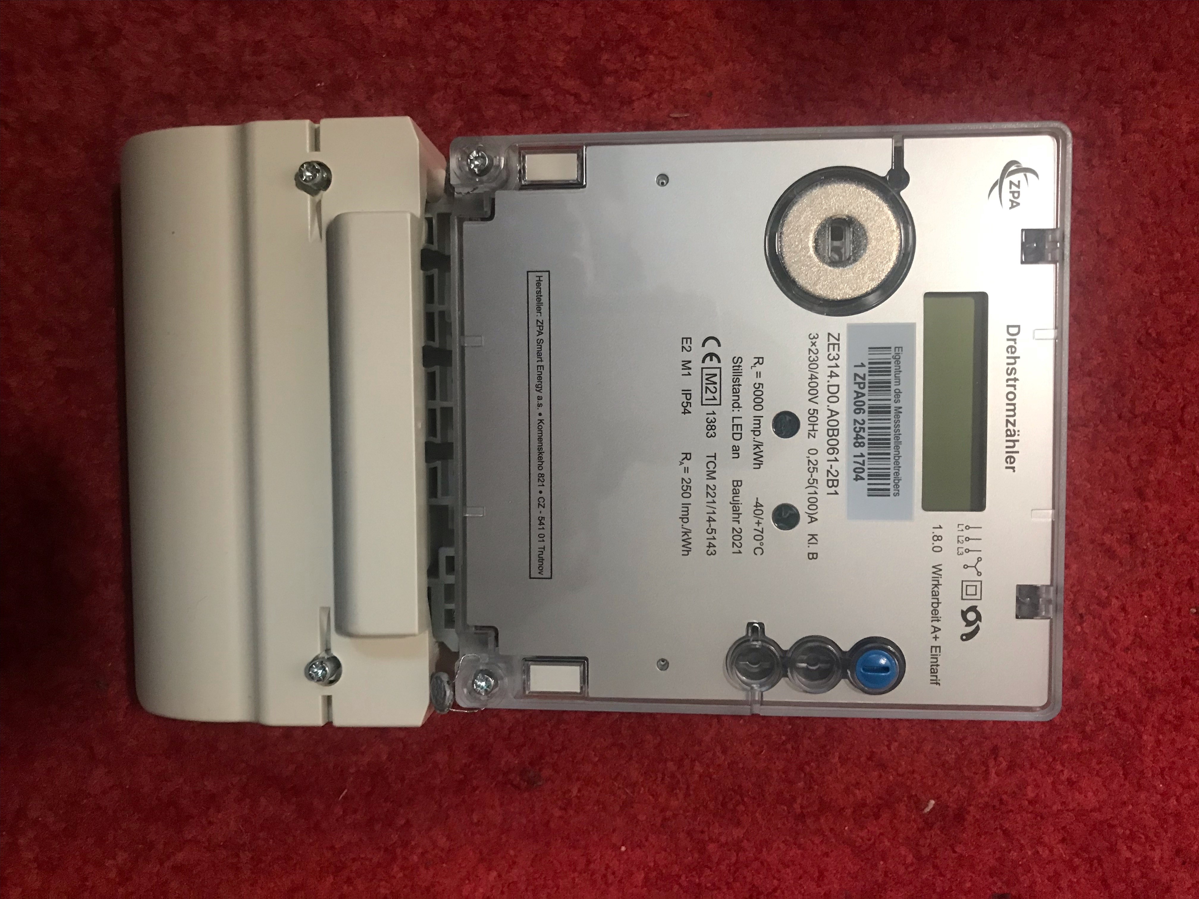
| 15:41, 2 March 2024 | U3.jpg (file) |  |
1.9 MB | Barney | 1 | |
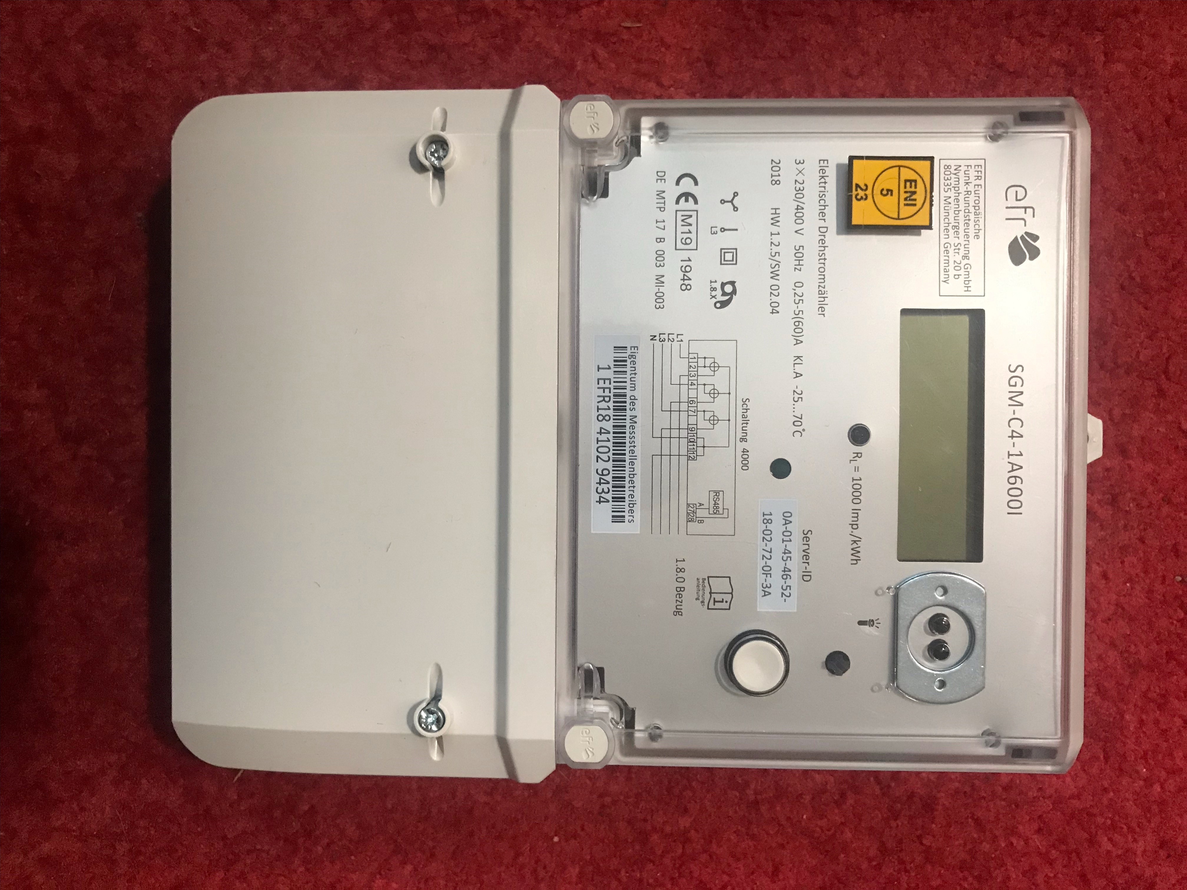
| 15:39, 2 March 2024 | U2.jpg (file) |  |
2.04 MB | Barney | 1 | |
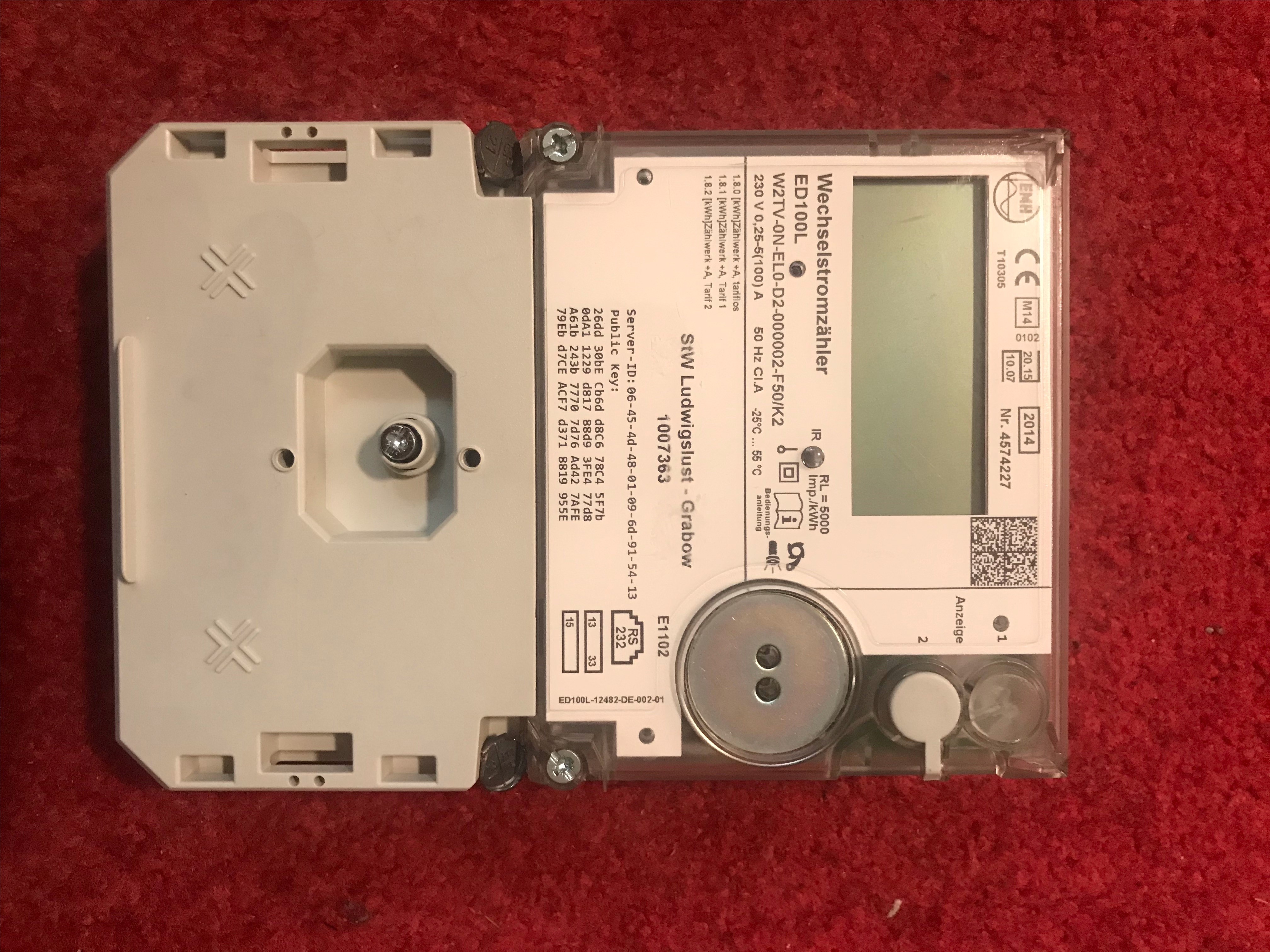
| 15:33, 2 March 2024 | U1.jpg (file) |  |
1.89 MB | Barney | 1 | |
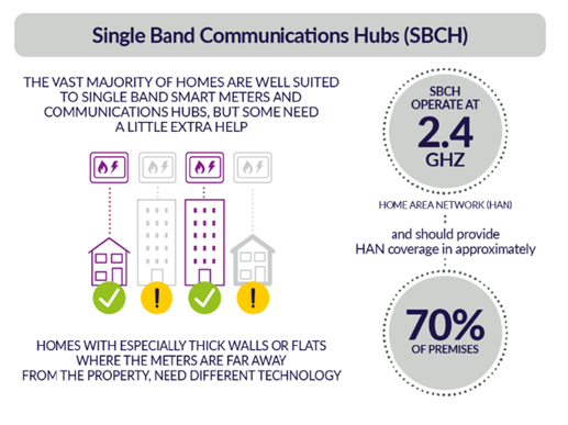
| 14:50, 2 March 2024 | 24GHZ.png (file) |  |
107 KB | Barney | 1 |