File list
This special page shows all uploaded files.
| Date | Name | Thumbnail | Size | User | Description | Versions |
|---|---|---|---|---|---|---|
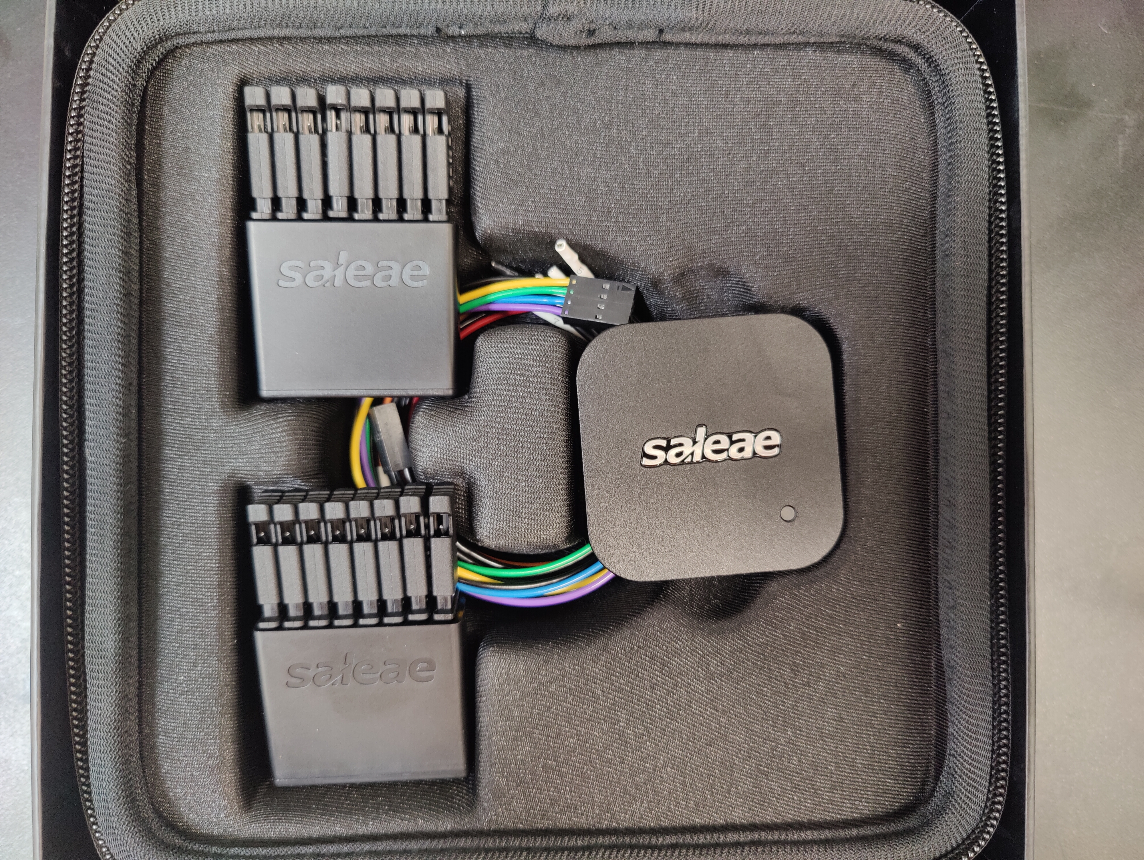
| 02:07, 2 October 2024 | Hacker Dojo - Logic 8 saleae Analyzer.jpg (file) |  |
9.48 MB | -.-6eau | 1 | |
| 02:06, 2 October 2024 | Instant Omni Pro TX Tek 1ms - 11110 - 5 Bits 8ms Measurement.jpg (file) |  |
82 KB | -.-6eau | 1 | |
| 02:02, 2 October 2024 | Instant Omni Pro TX Tek 250us - 890us Single High Square Wave Measurement.jpg (file) |  |
82 KB | -.-6eau | 1 | |
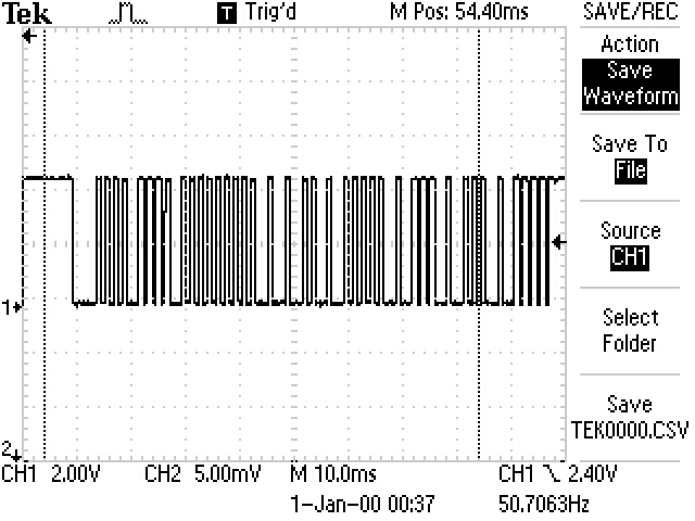
| 02:00, 2 October 2024 | Instant Omni Pro TX Tek 10ms Single Message.jpg (file) |  |
96 KB | -.-6eau | 1 | |
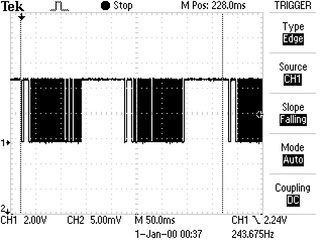
| 01:59, 2 October 2024 | Instant Omni Pro TX Tek 50ms.jpg (file) |  |
85 KB | -.-6eau | 1 | |
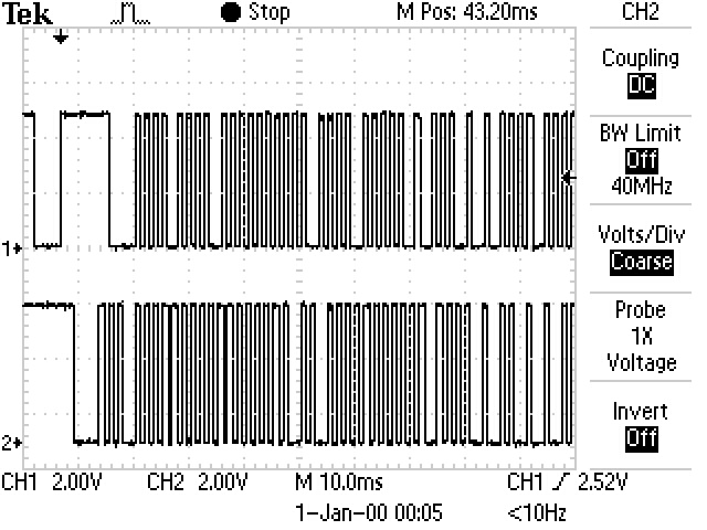
| 01:58, 2 October 2024 | Instant Omni Pro TX-RX Tek 10ms.jpg (file) |  |
106 KB | -.-6eau | 1 | |
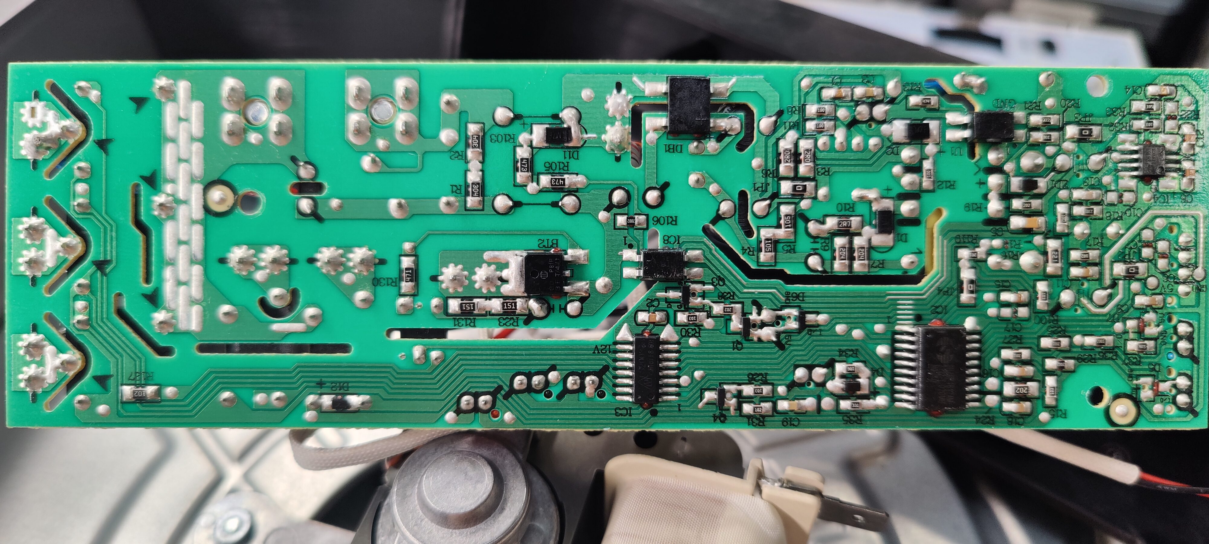
| 01:55, 2 October 2024 | Instant Omni Pro EK-180X10C-US-P PCB Bottom.jpg (file) |  |
5.05 MB | -.-6eau | 1 | |
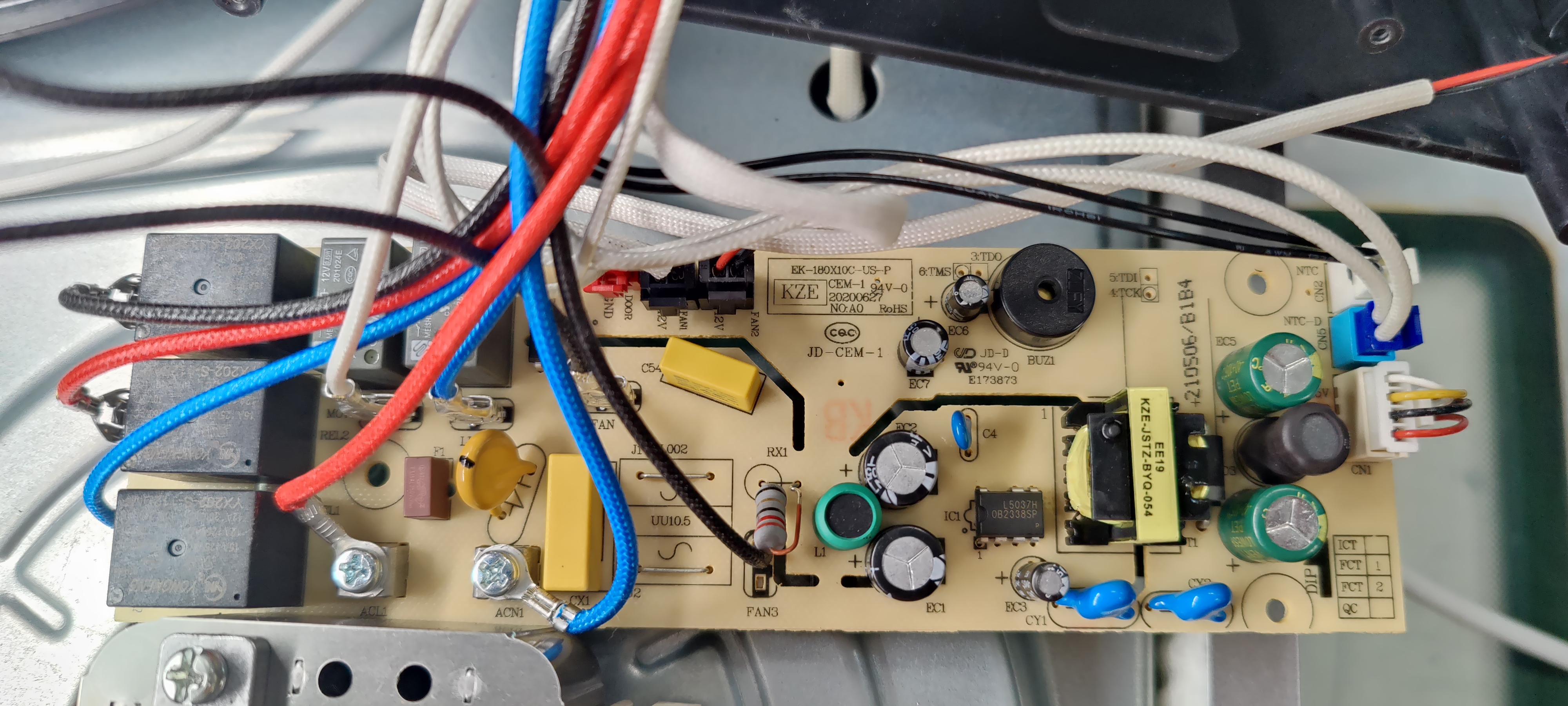
| 01:54, 2 October 2024 | Instant Omni Pro EK-180X10C-US-P PCB Top.jpg (file) |  |
2.88 MB | -.-6eau | 1 | |
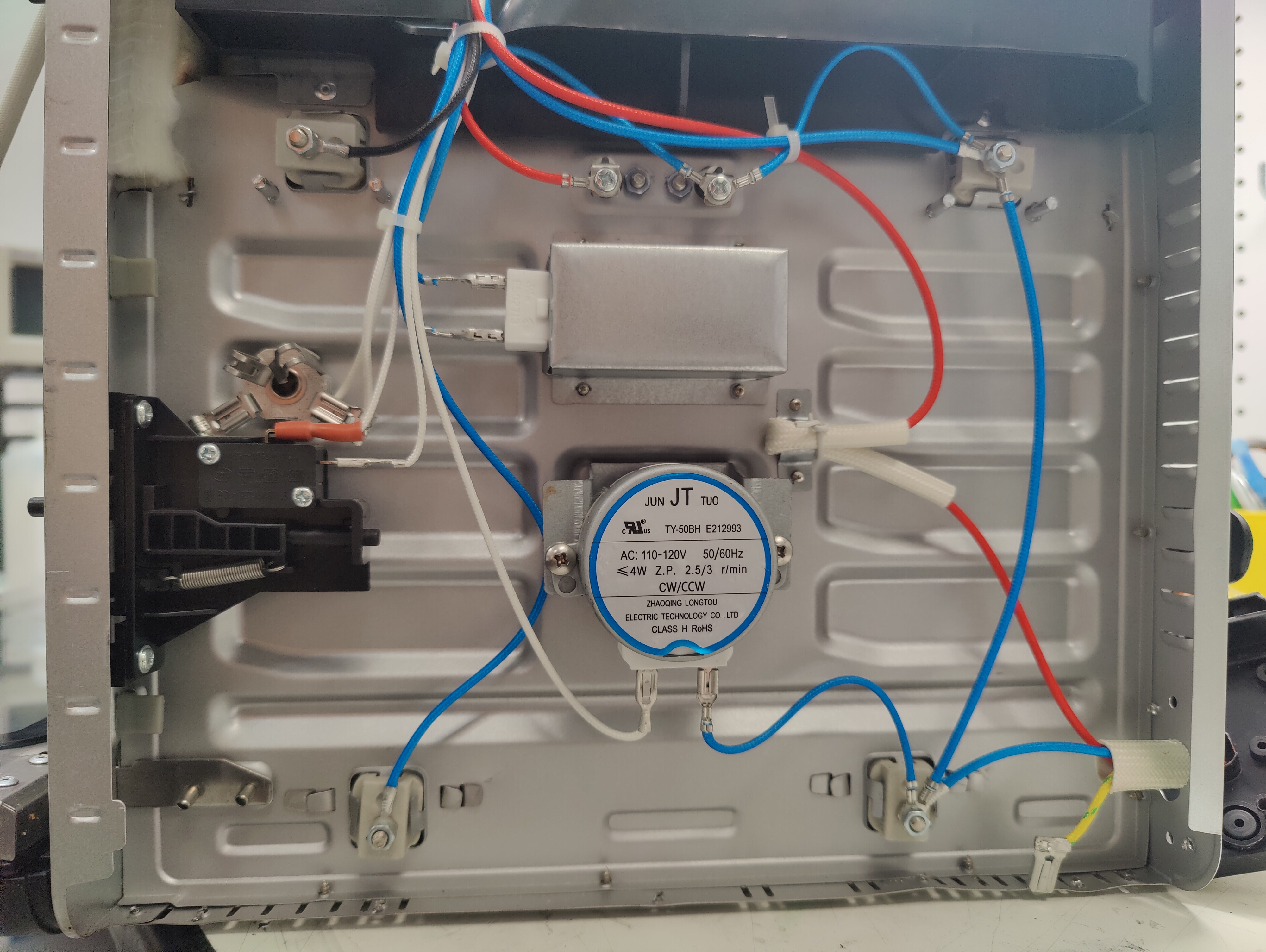
| 01:51, 2 October 2024 | Instant Omni Pro Top Uncovered.jpg (file) |  |
7.3 MB | -.-6eau | 1 | |
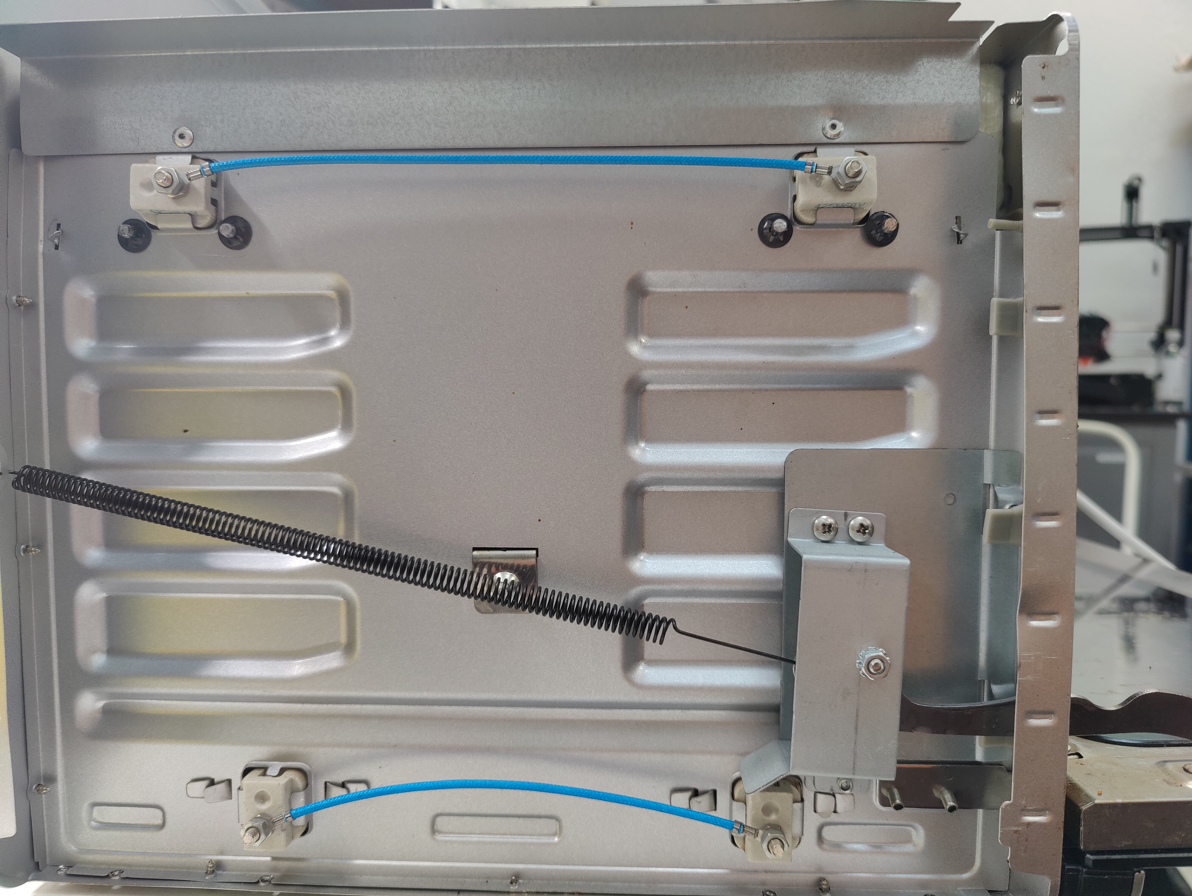
| 01:50, 2 October 2024 | Instant Omni Pro Left Side Uncovered.jpg (file) |  |
5.85 MB | -.-6eau | 1 | |
| 01:50, 2 October 2024 | Instant Omni Pro Left Side Uncovered .jpg (file) |  |
6.86 MB | -.-6eau | 1 | |
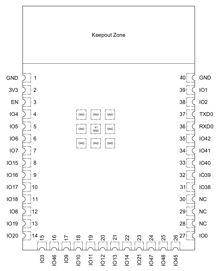
| 16:42, 25 September 2024 | ESP32-S3-WROOM2 Pin Layout.png (file) |  |
79 KB | -.-6eau | 1 | |
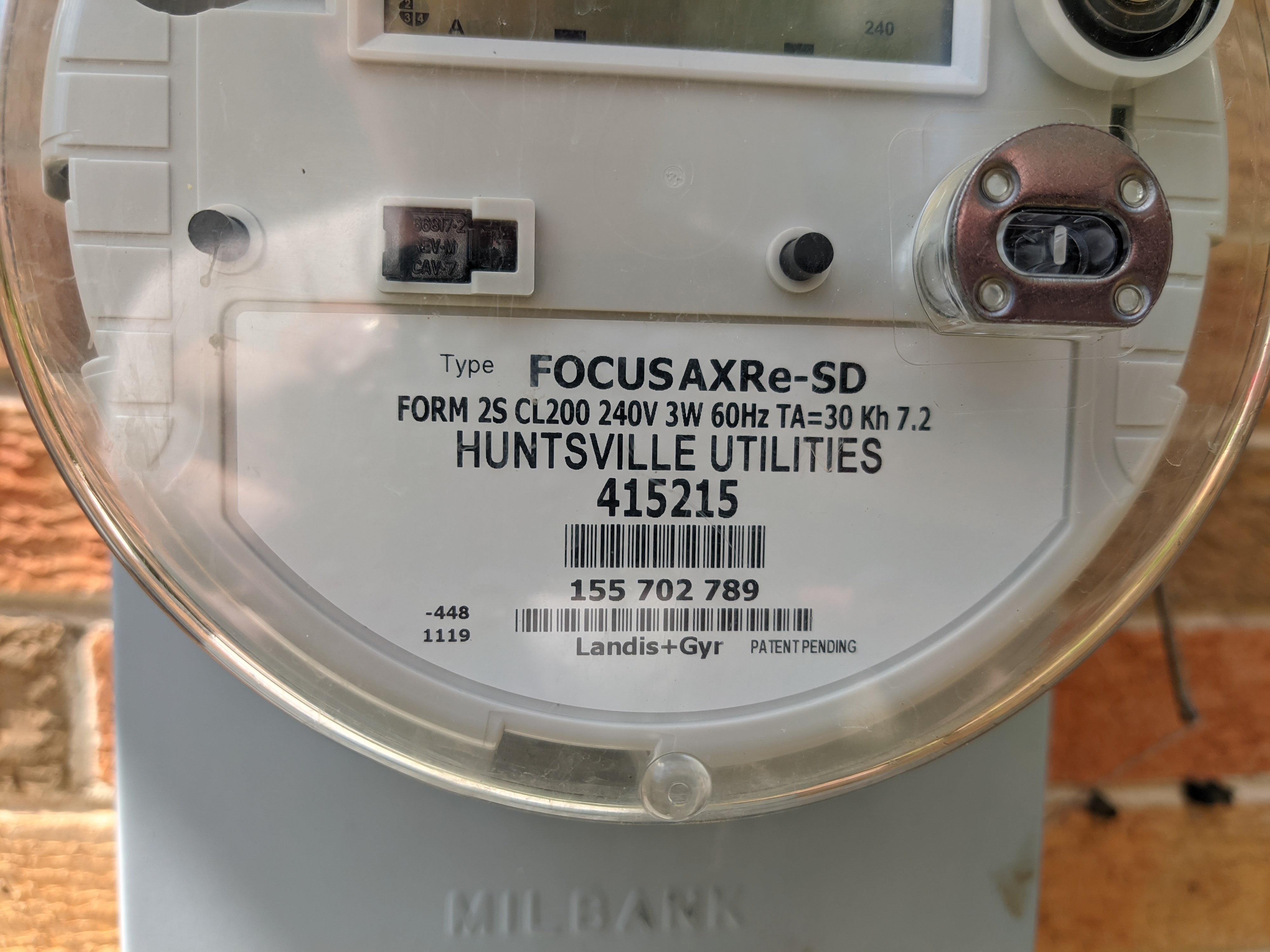
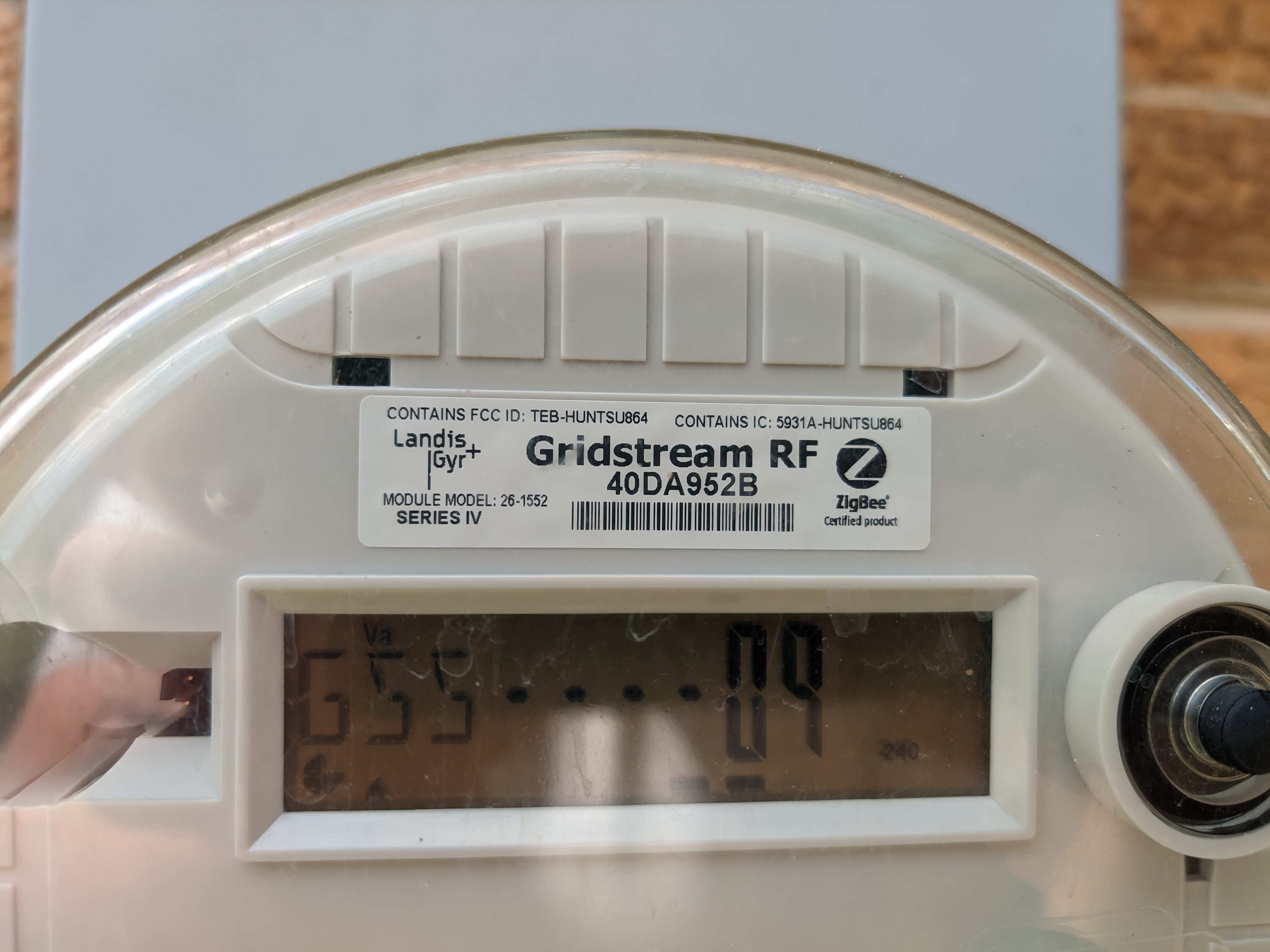
| 02:36, 23 September 2024 | PXL 20240920 184923808.MP.jpg (file) |  |
2.55 MB | Ctag | 1 | |
| 02:34, 23 September 2024 | PXL 20240920 184927492.MP.jpg (file) |  |
2.13 MB | Ctag | 1 | |
| 03:05, 19 September 2024 | WF121-A internal.png (file) |  |
1.17 MB | -.-6eau | 1 | |
| 03:05, 19 September 2024 | WF121-A top.png (file) |  |
926 KB | -.-6eau | 1 | |
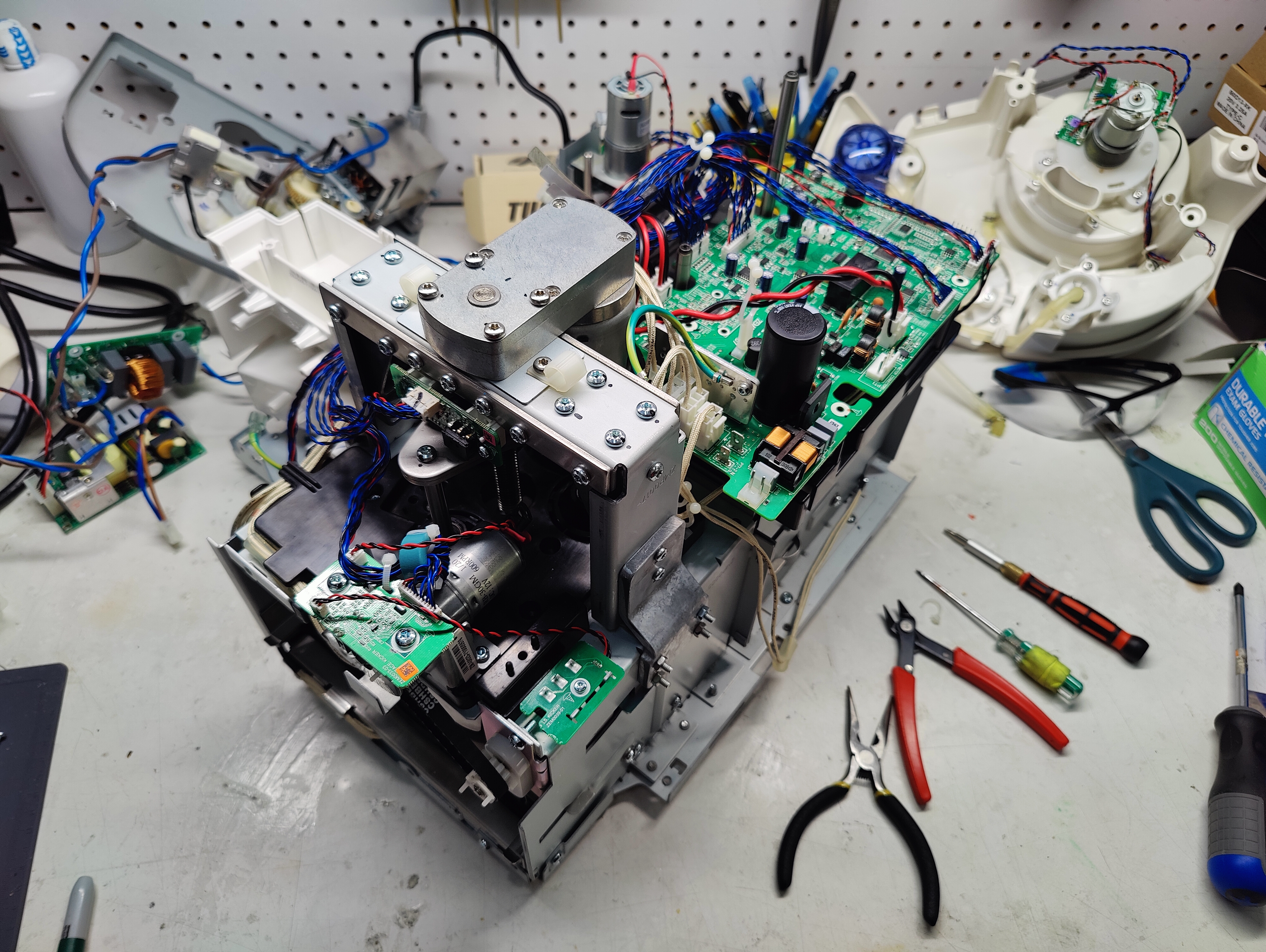
| 07:37, 7 September 2024 | Roti rotimatic top disassembled.jpg (file) |  |
7.68 MB | -.-6eau | Complete enclosure and mixer disassembly with AC power supply components removed. | 1 |
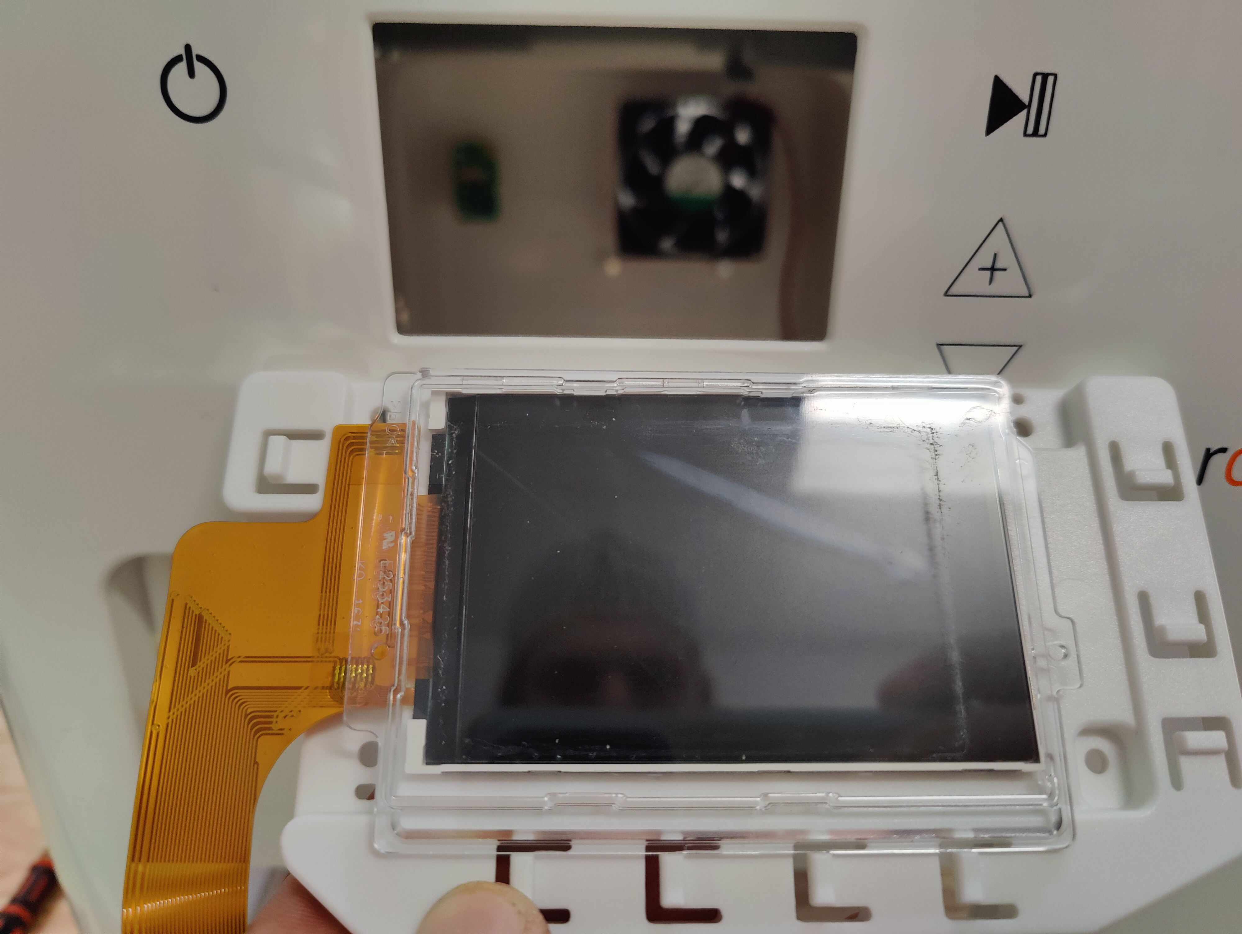
| 07:35, 7 September 2024 | Roti rotimatic LCD cover cropped.jpg (file) |  |
6 MB | -.-6eau | Front panel LED showing cropped portion (dust/dirt line) of right and top edges of screen when fitted behind front enclosure. | 1 |
| 07:32, 7 September 2024 | Roti rotimatic HVDC filter US ZEM0041-01 PCB inductors.jpg (file) |  |
5.76 MB | -.-6eau | Bottom view of ZEM0041-01 PCB with two 104 Coilcraft inductors. | 1 |
| 07:30, 7 September 2024 | Roti rotimatic HVDC filter US ZEM0041-01 fuse coil.jpg (file) |  |
5.66 MB | -.-6eau | High Voltage DC Filter for US 120 volt AC with multiple fuses and components. | 1 |
| 07:28, 7 September 2024 | Roti rotimatic .jpg (file) |  |
6.42 MB | -.-6eau | Side view of brown mains wire with extra insulation folded and secured enclosing thermal safety disconnect fuse. | 1 |
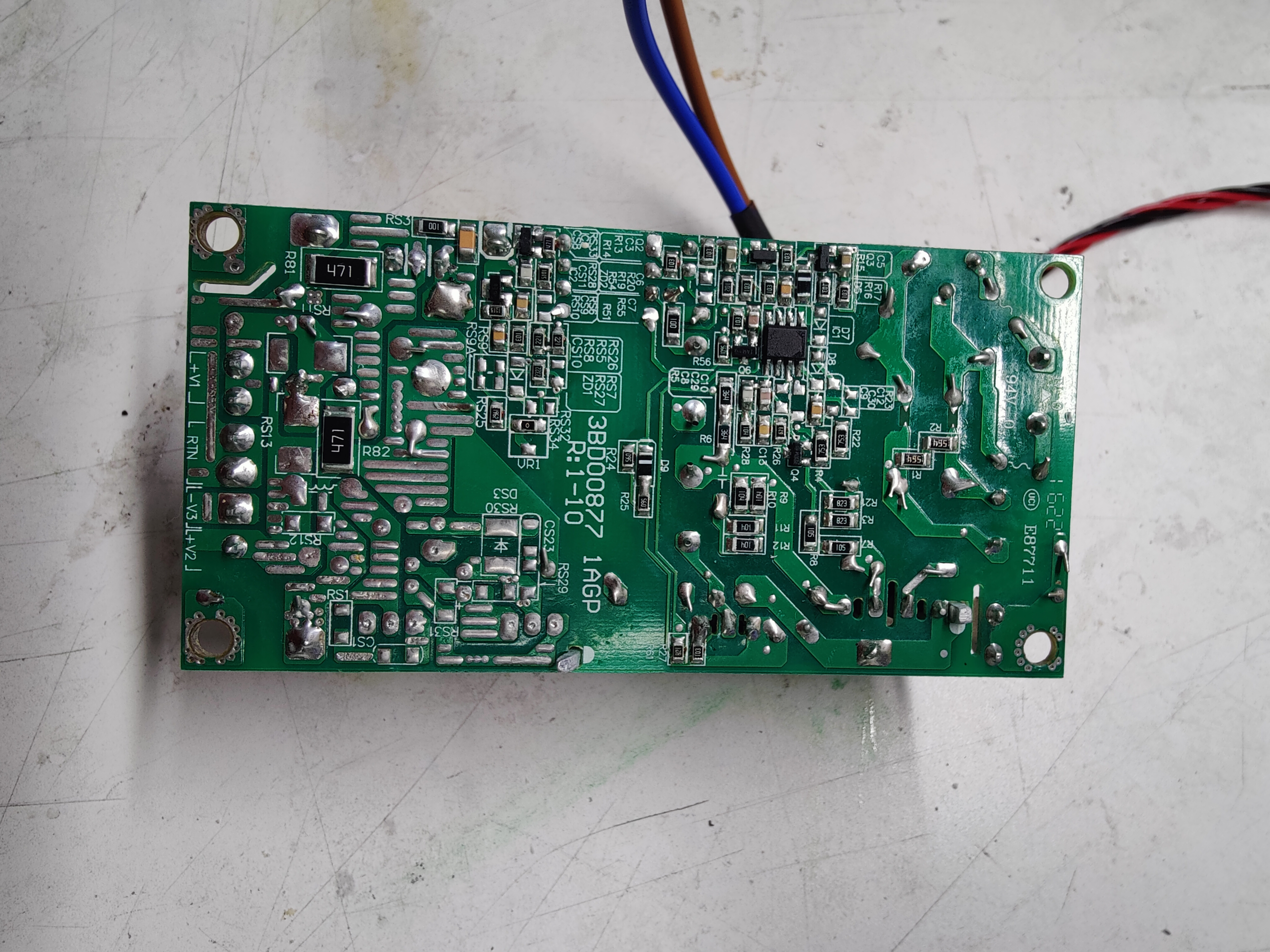
| 07:26, 7 September 2024 | Roti rotimatic main AC PCB bottom 3BD00877 1AGp.jpg (file) |  |
6.15 MB | -.-6eau | US 120 volt AC circuit board. | 1 |
| 07:24, 7 September 2024 | Roti rotimatic main AC high voltage power input board.jpg (file) |  |
5.72 MB | -.-6eau | Main power assembly directly connected to AC mains input. High voltage capacitor and components. | 1 |
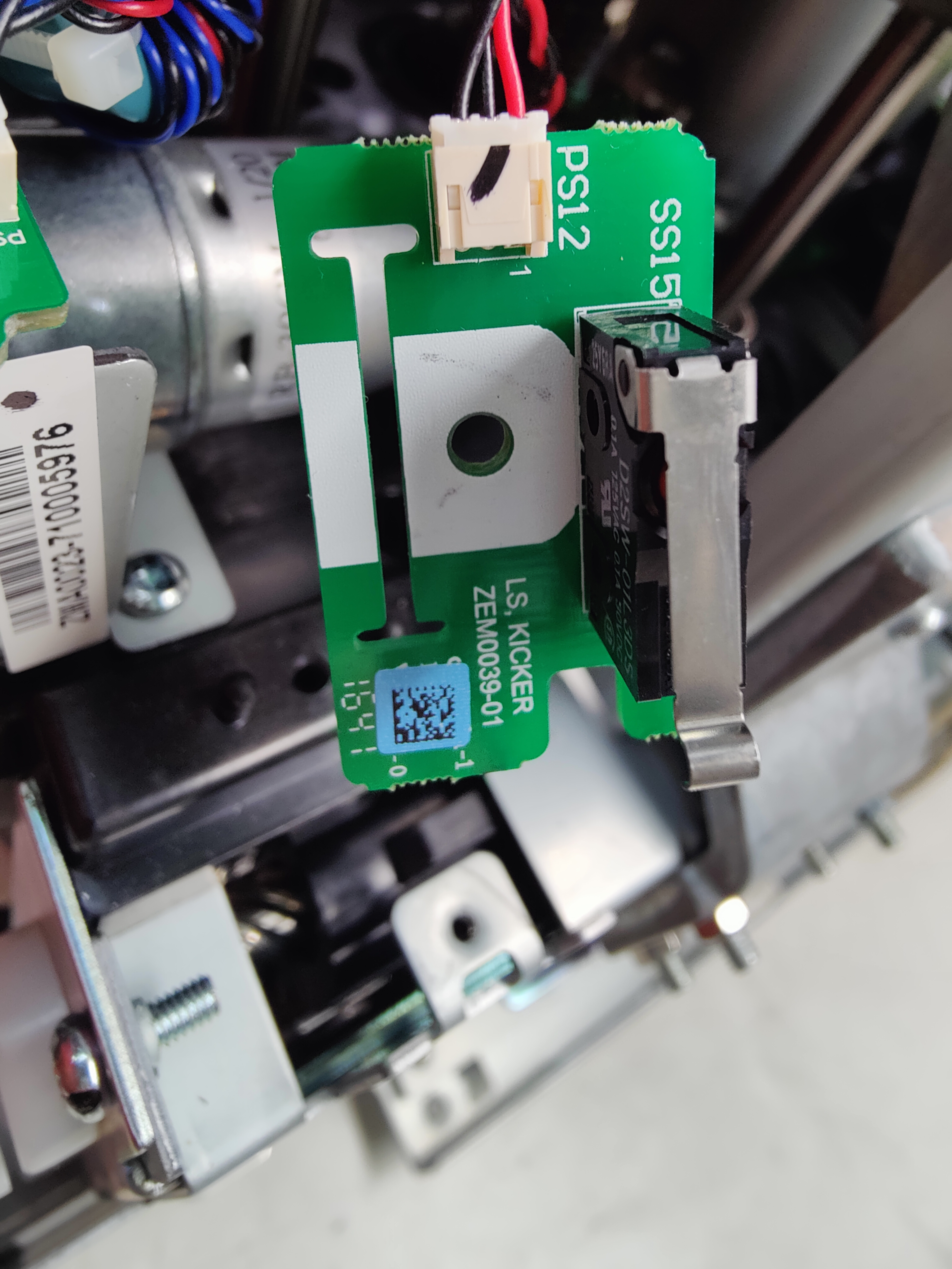
| 07:21, 7 September 2024 | Roti rotimatic kicker limit switch.jpg (file) |  |
5.03 MB | -.-6eau | Limit switch that detects full retraction of "Kicker", note plastic piece with raised section visible thru gap directly below bottom of PCB attached to screw rod. | 1 |
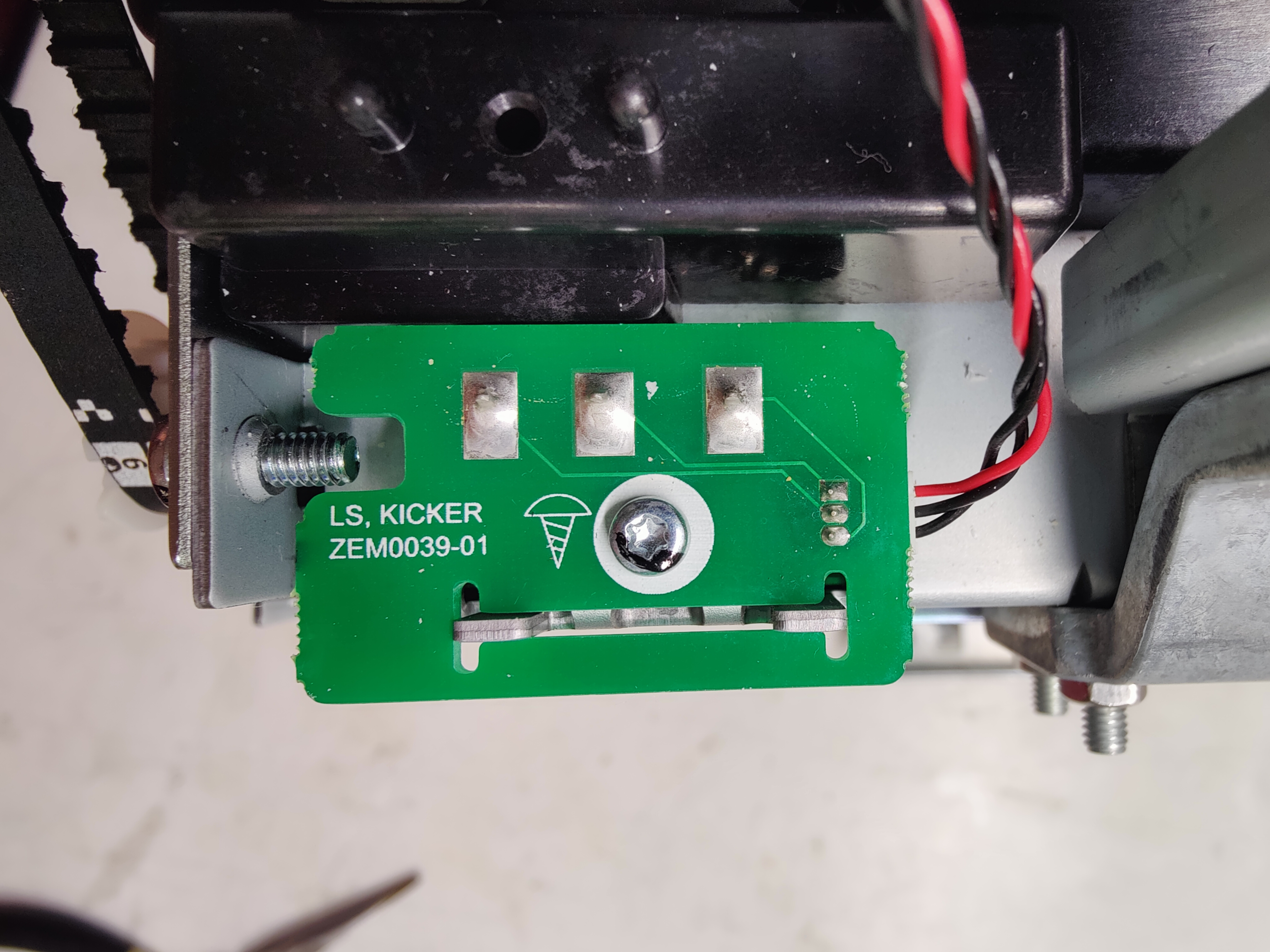
| 07:19, 7 September 2024 | Roti rotimaker kicker limit switch PCB back.jpg (file) |  |
5.07 MB | -.-6eau | "Kicker" PCB for limit switch. | 1 |
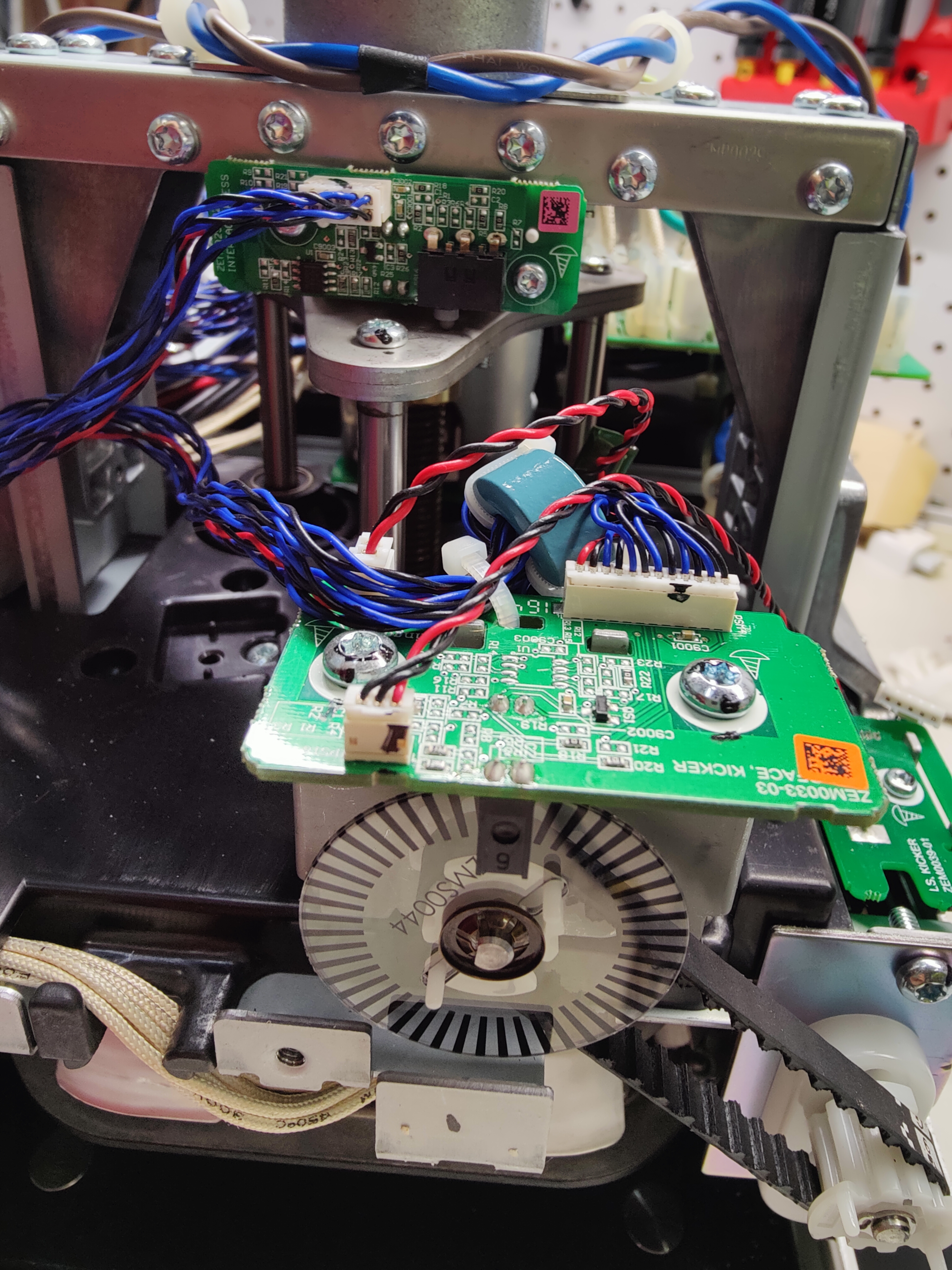
| 07:17, 7 September 2024 | Roti rotimatic kicker PCB optical encoder belt gears .jpg (file) |  |
6.55 MB | -.-6eau | "Kicker" PCB that controls the horizontal roti pusher/ejector from back to front inside machine. Optical IR encoder wheel/disc connected to motor, belt and gear assembly. Upper PCB has upper limit switch for vertical pressing motor. | 1 |
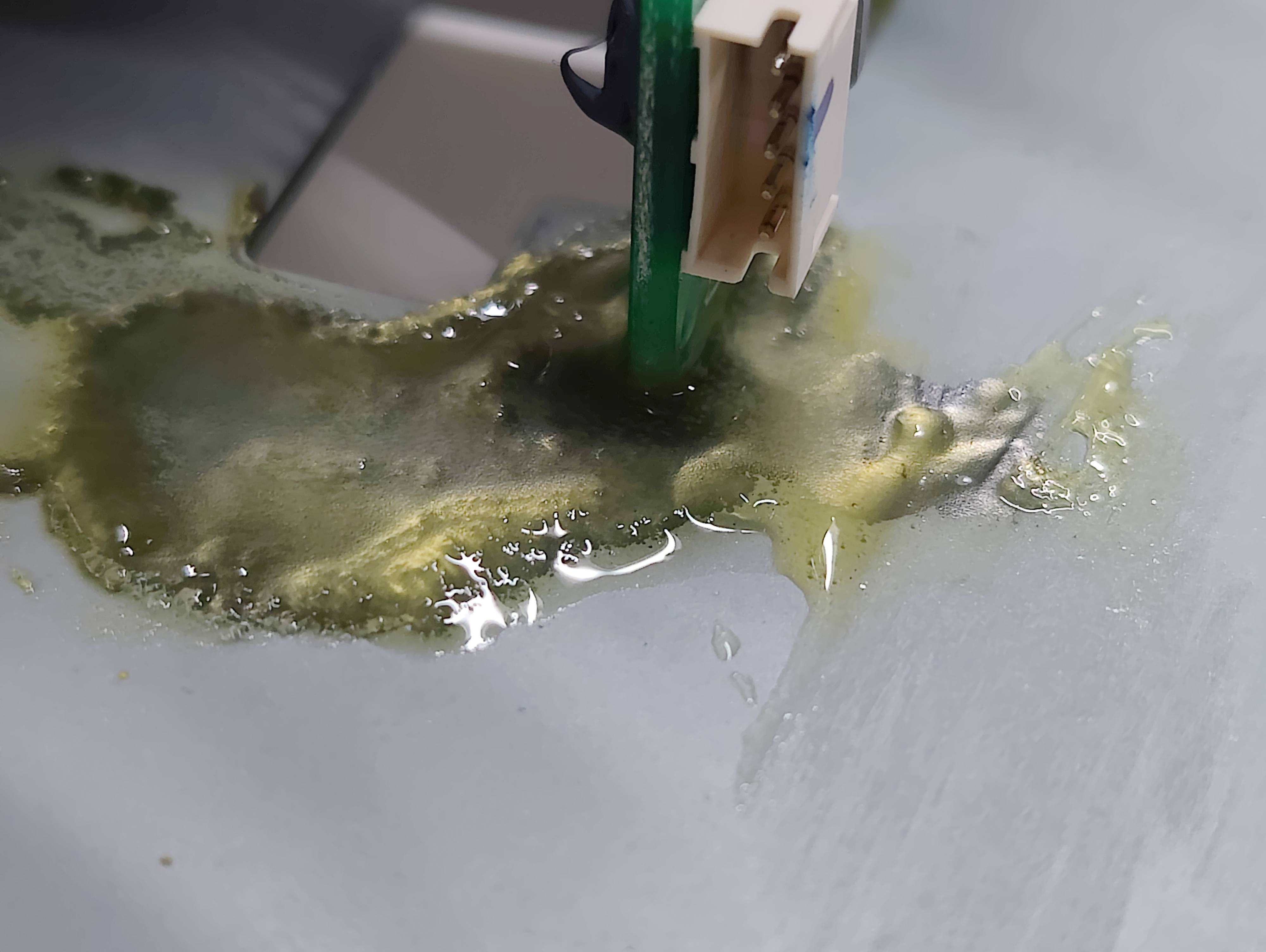
| 07:13, 7 September 2024 | Roti rotimatic oil damage under load cell PCB .jpg (file) |  |
2.26 MB | -.-6eau | Small puddle of oil corroding metal under PCB connected to load cell. | 1 |
| 07:11, 7 September 2024 | Roti rotimatic complete load cell mixer motor.jpg (file) |  |
7 MB | -.-6eau | Load cell and sensor PCB with geared motor assembly. | 1 |
| 07:09, 7 September 2024 | Roti rotimatic load cell mixer motor.jpg (file) |  |
5.75 MB | -.-6eau | Load cell and sensor PCB with geared motor assembly. | 1 |
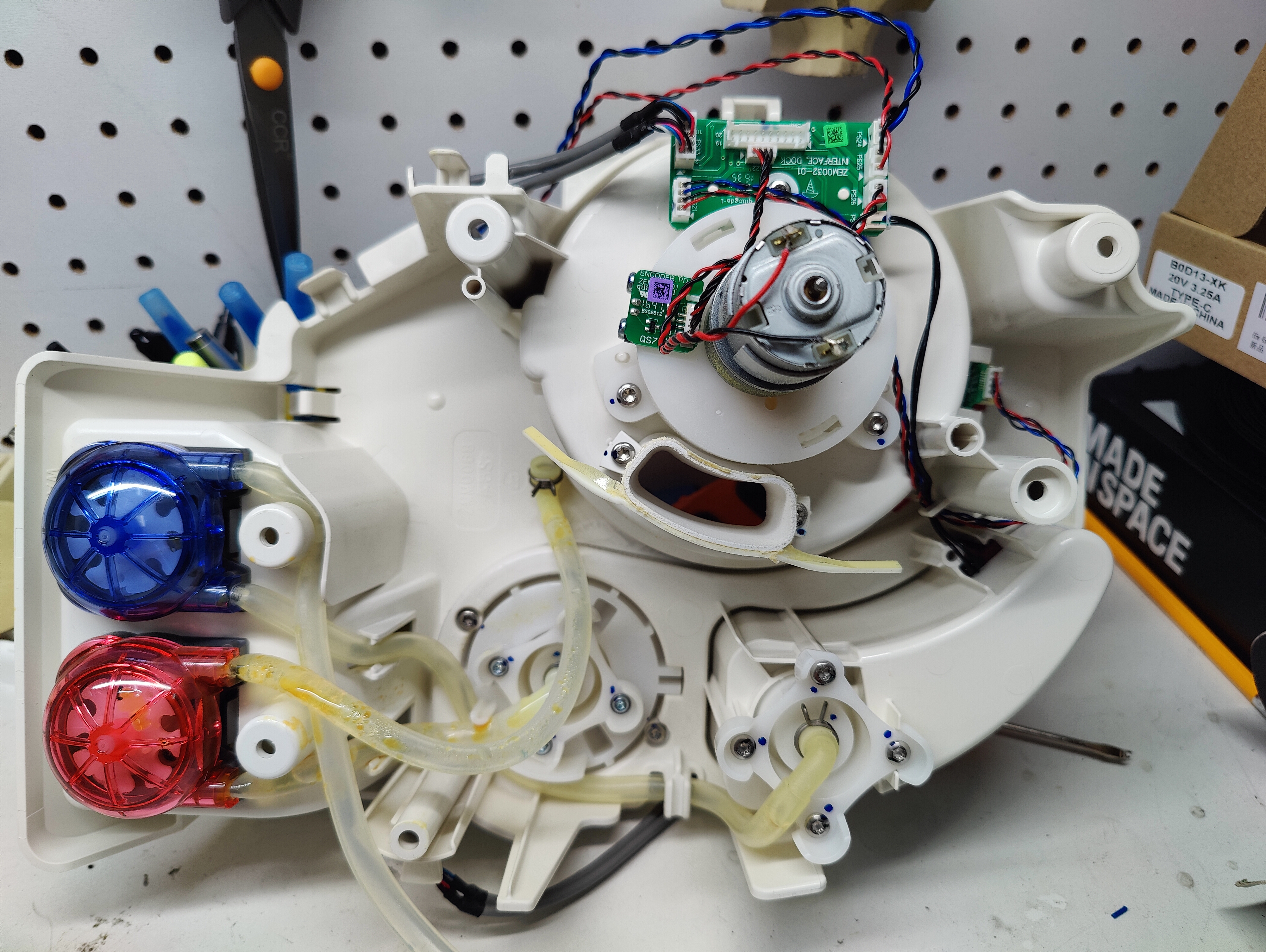
| 07:06, 7 September 2024 | Roti rotimatic flour water oil dispenser bottom.jpg (file) |  |
7.29 MB | -.-6eau | Bottom view of flour, water and oil dispensers with pumps motor tubes and sensors. | 1 |
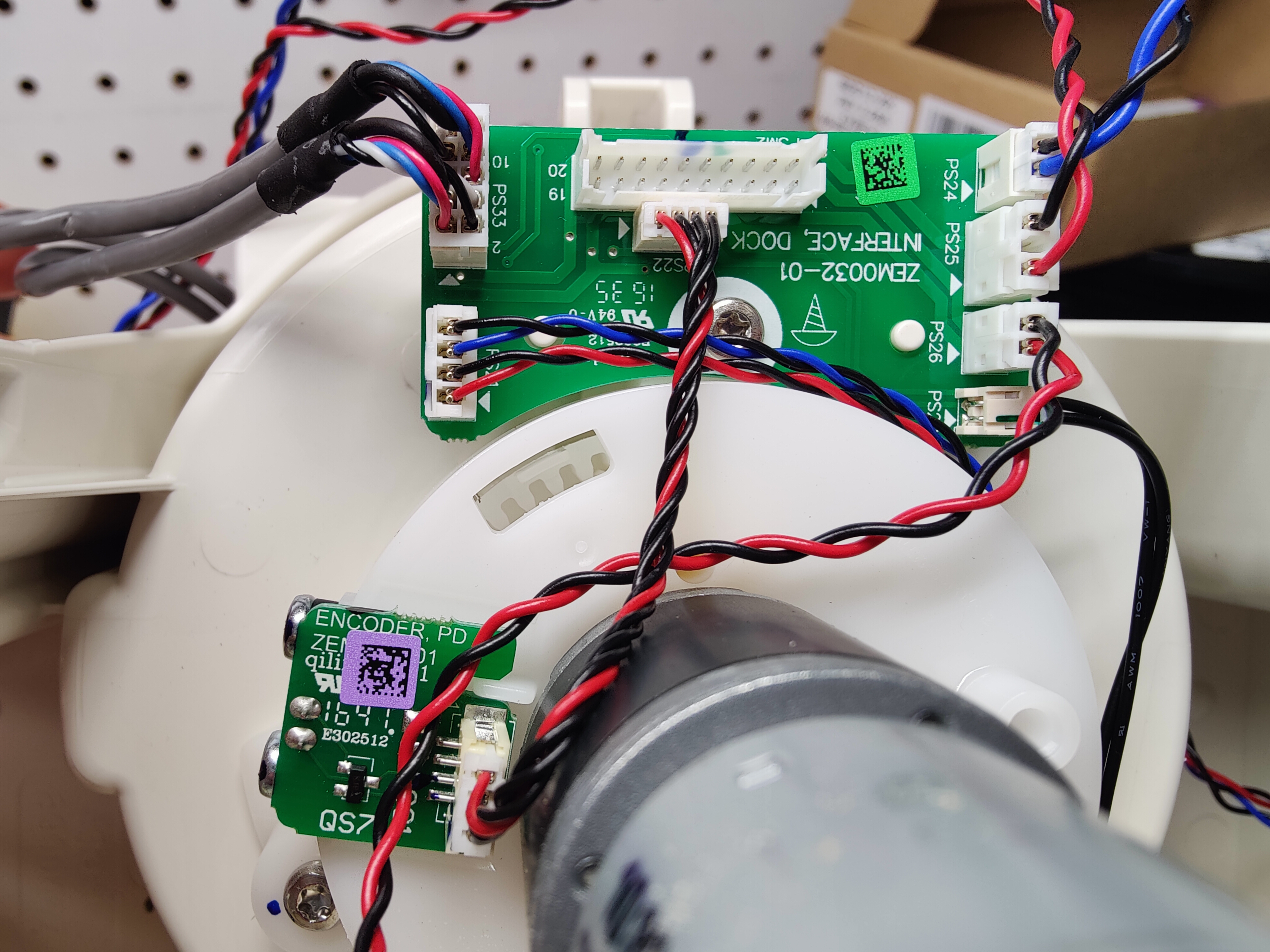
| 07:04, 7 September 2024 | Roti rotimatic flour dispenser motor PCB boards encoder.jpg (file) |  |
5.42 MB | -.-6eau | Bottom view of flour dispenser mechanism located on top of the machine. PCB board for distribution of multiple connectors and separate encoder board for motor. ZEM0032-01 INTERFACE, DOCK ZEM####-01 ENCODER, PD | 1 |
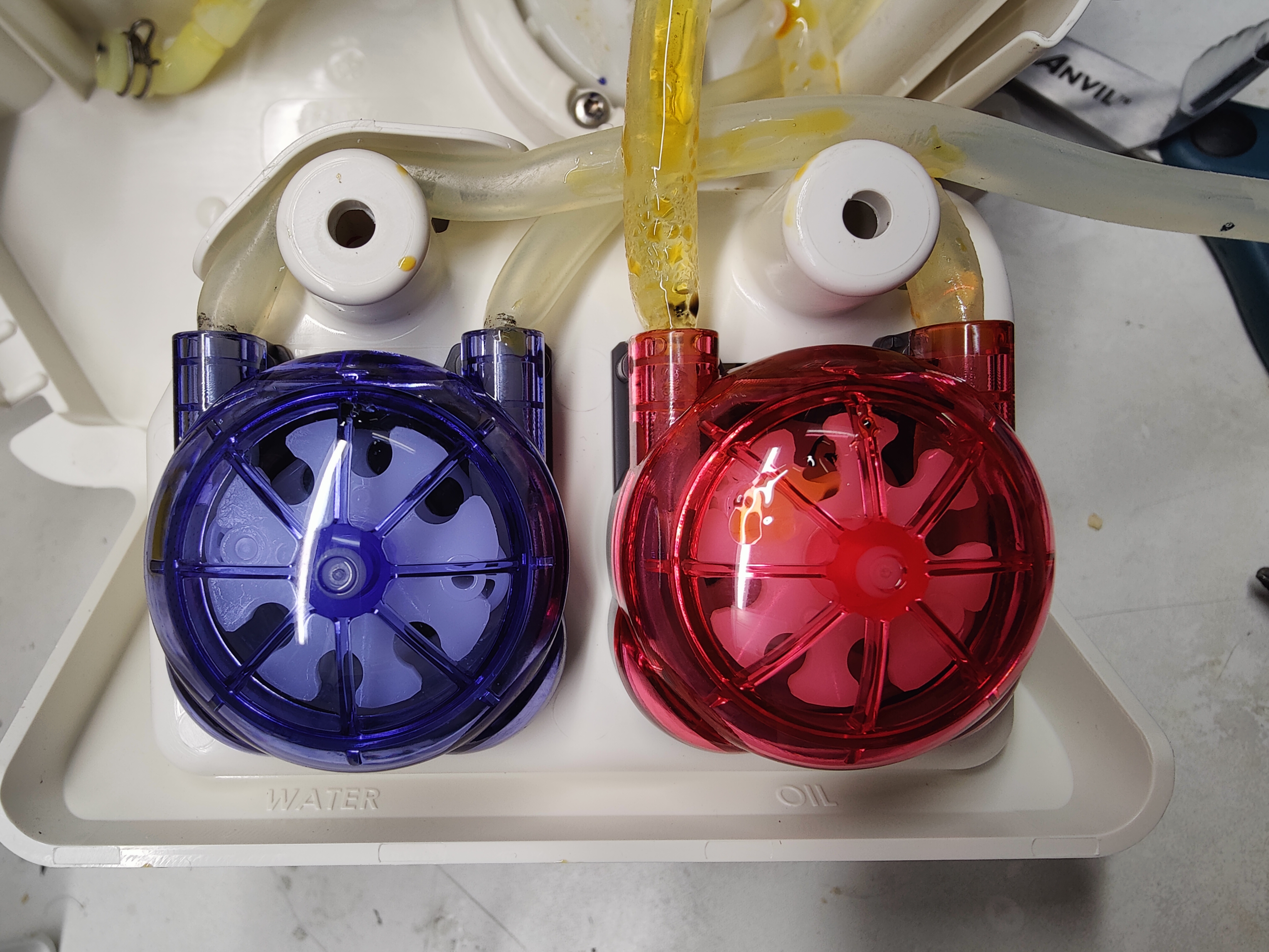
| 06:59, 7 September 2024 | Roti rotimatic two peristaltic pumps water oil.jpg (file) |  |
5.91 MB | -.-6eau | Blue'ish and red'ish peristaltic pumps for water and oil driven by DC motors. | 1 |
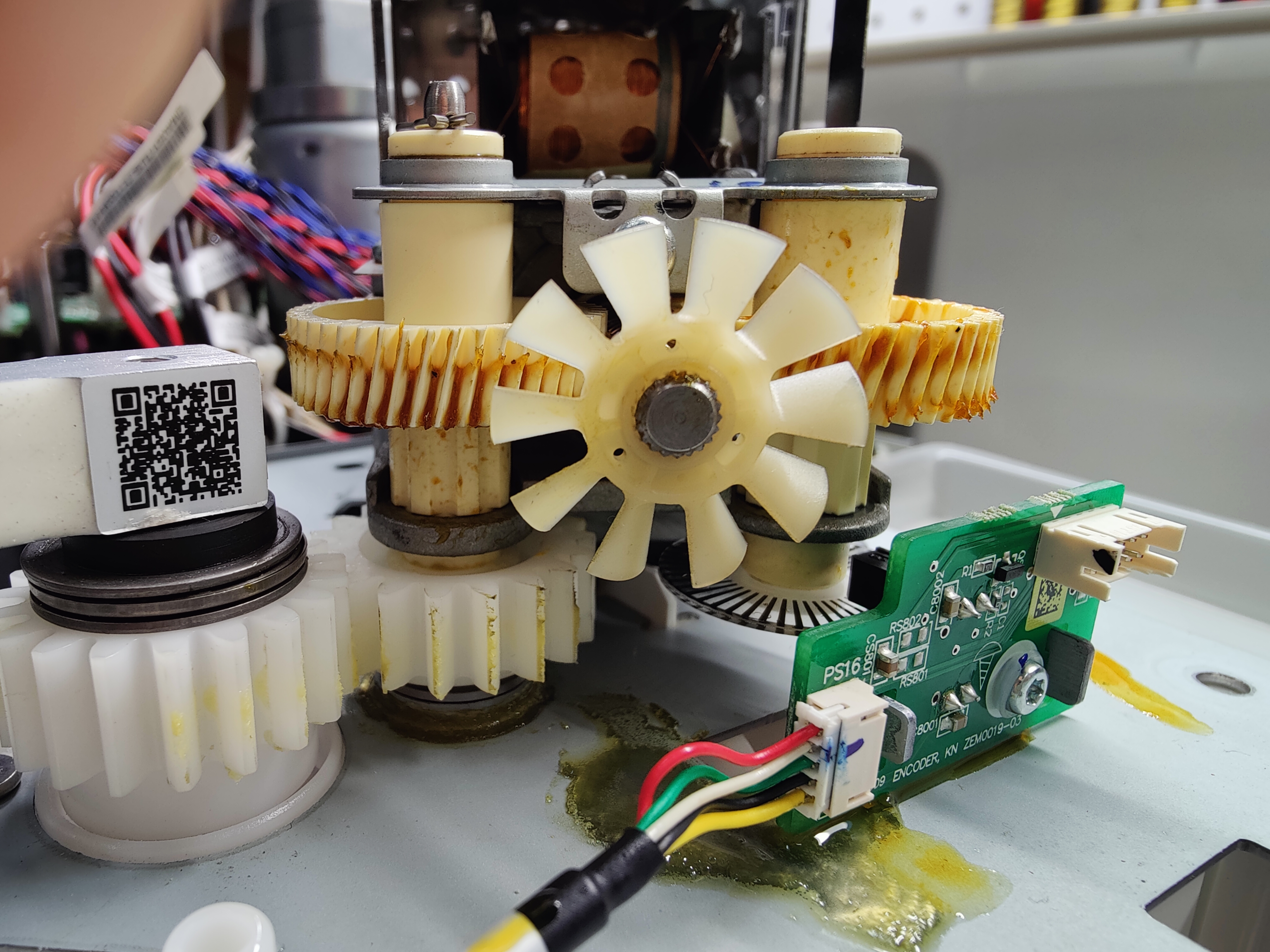
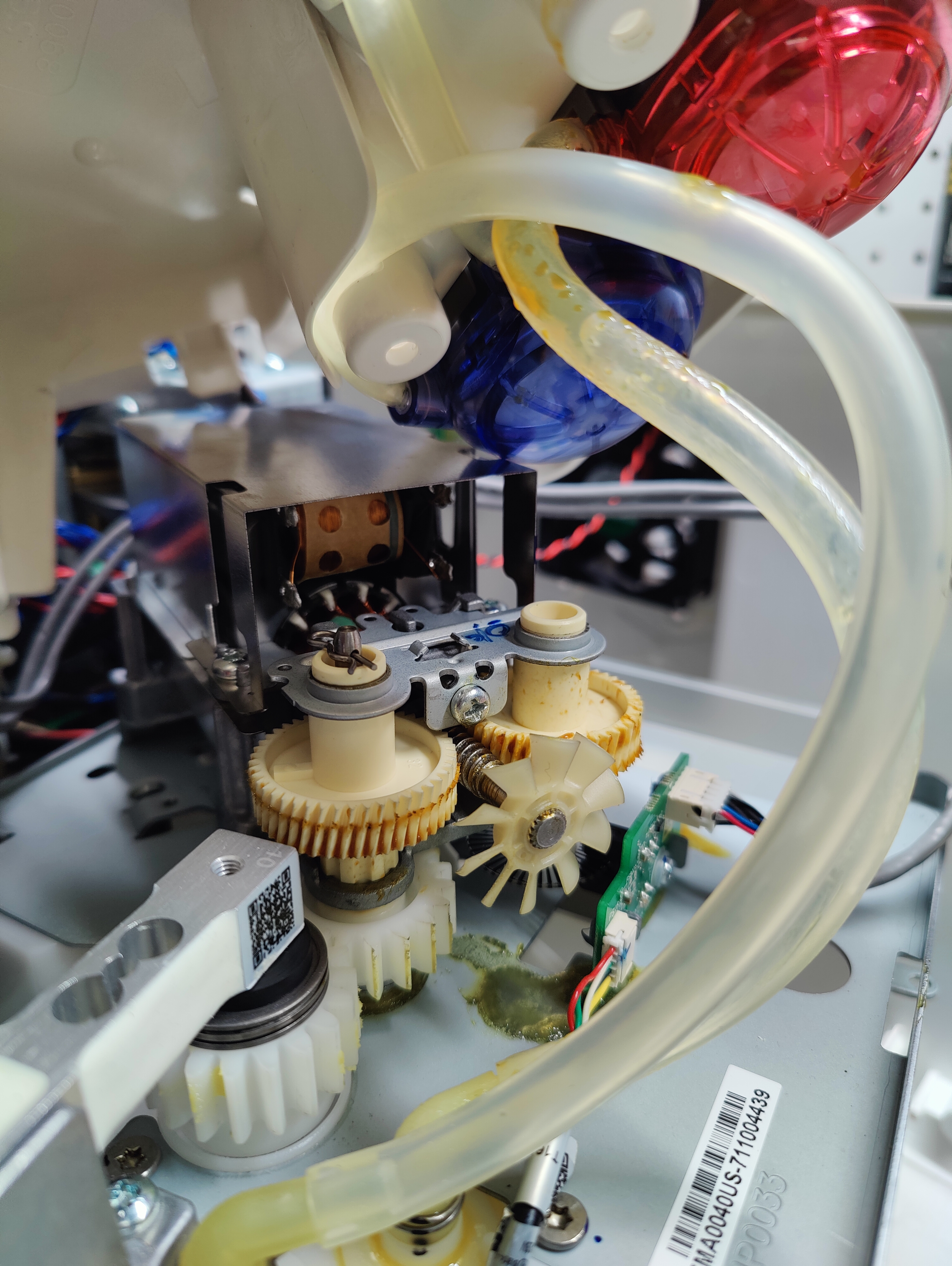
| 06:57, 7 September 2024 | Roti rotimatic high speed mixer motor gears load cell.jpg (file) |  |
6.52 MB | -.-6eau | Closer view of high speed motor with horizontal metal screw drive to plastic gears and cooling fan at end of shaft. Load cell in lower left and red/blue pumps upper right. | 1 |
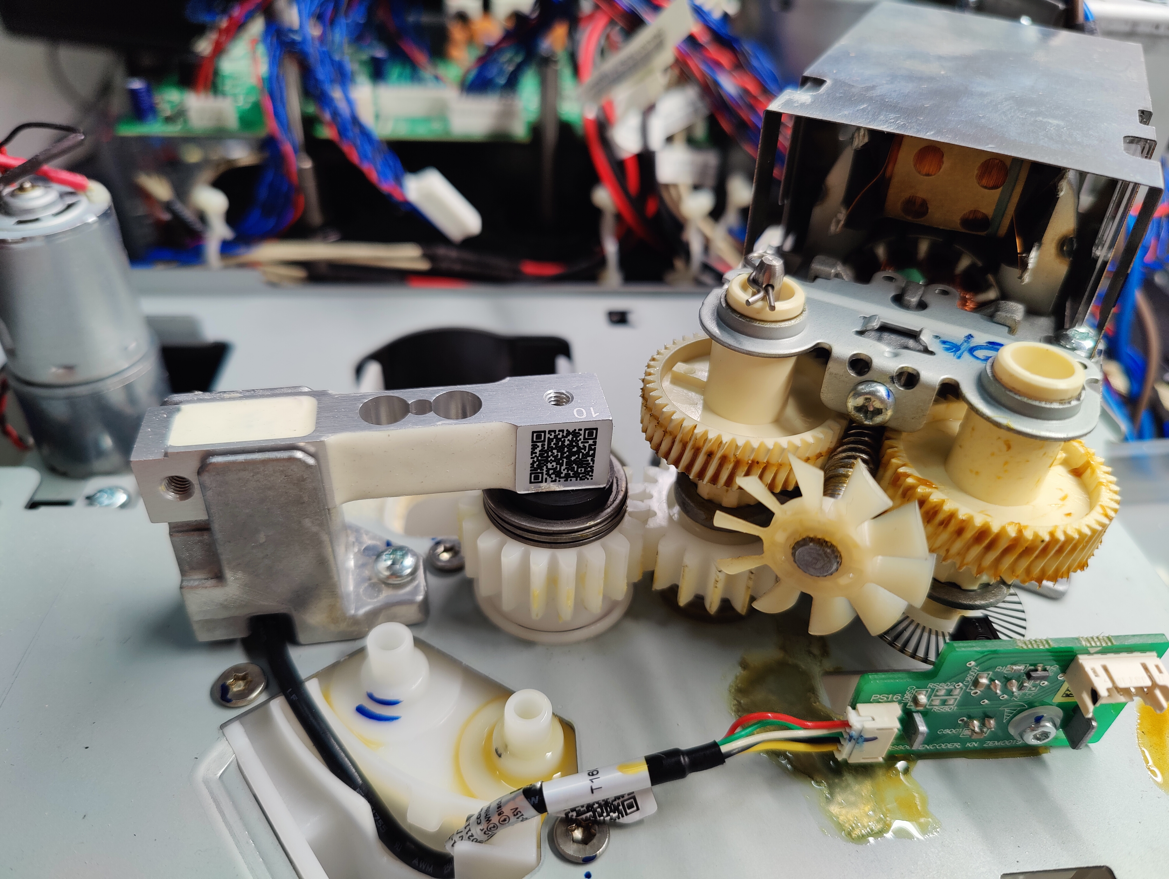
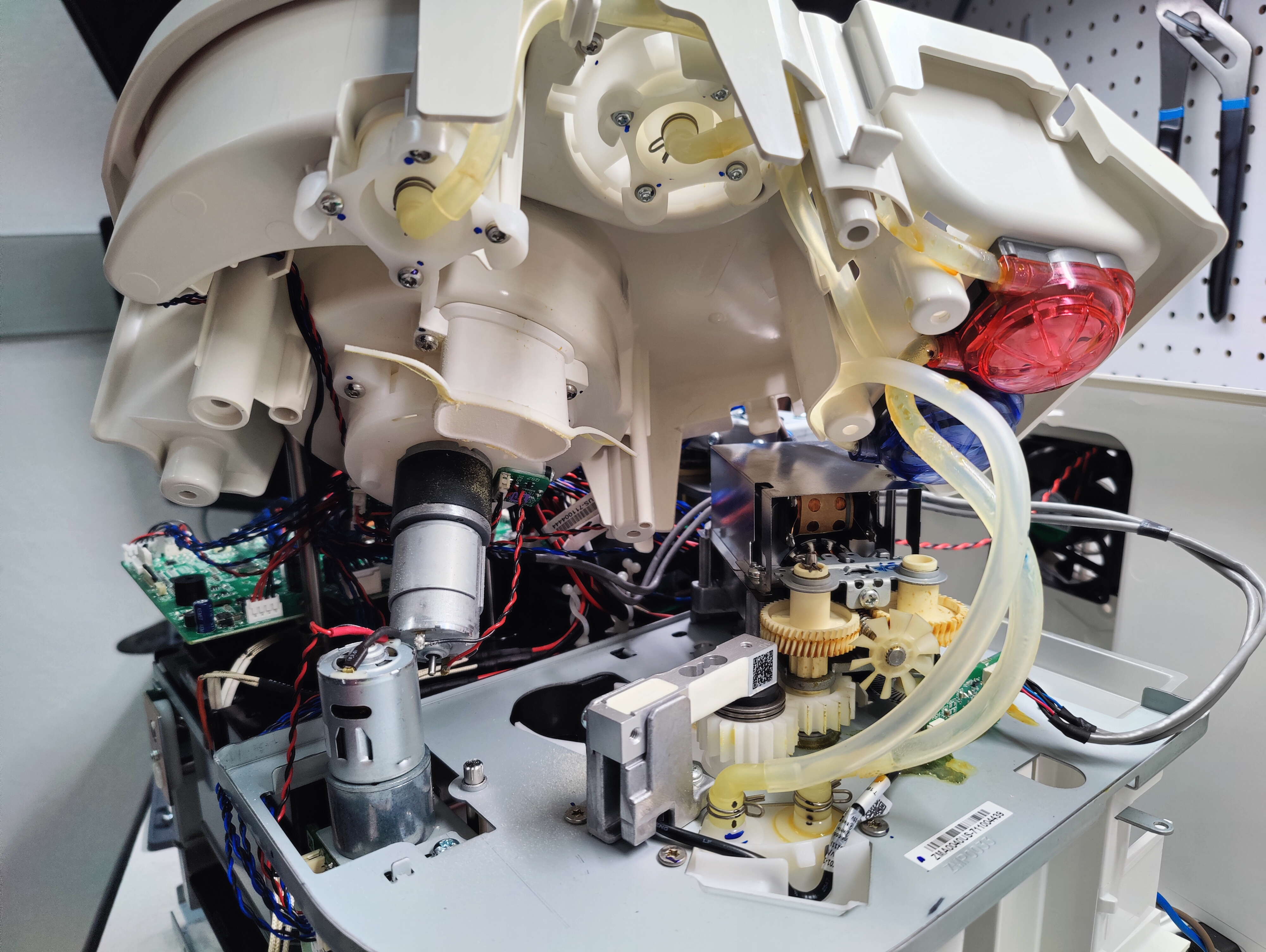
| 06:53, 7 September 2024 | Roti rotimatic mixing gears motors pumps tubes load cell.jpg (file) |  |
6.64 MB | -.-6eau | Removal of upper mixer assembly with attached DC motor and two pumps. Motor with lower limit switch and ir sensor on left. Center is a load cell with inscription "10" connected to series of gears driven by horizontally mounted motor. Two tubes from pump connect with spring clips and load cell PCB. | 1 |
| 06:48, 7 September 2024 | Roti rotimatic RB-30GM 12 volt DC geared motor ir disc.jpg (file) |  |
5.02 MB | -.-6eau | RB-30GM 12 volt DC motor with gear box connected to shaft with disc/wheel for ir position sensor. Installed at front-right side of machine and read by ZEM0031-04 PCB. | 1 |
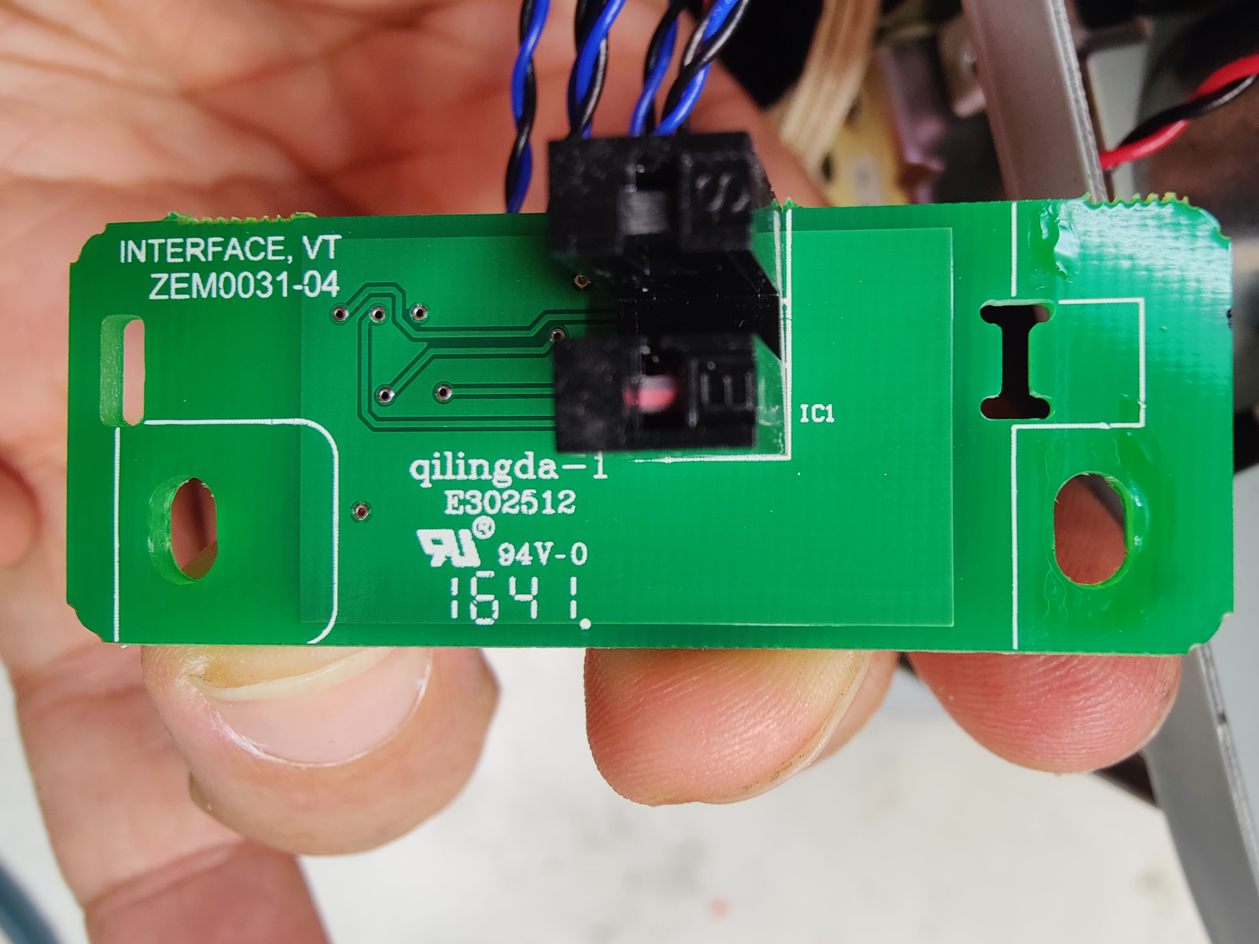
| 06:43, 7 September 2024 | Roti rotimatic connectors ir limit switch ZEM0031-04 back.jpg (file) |  |
5.26 MB | -.-6eau | Back of infrared sensor with connectors to main board and lower limit switch. R19 unpopulated, R18 populated with 0 ohm resistor jumper and 3 discrete SMD capacitors. ZEM0031-04 INTERFACE, VT | 1 |
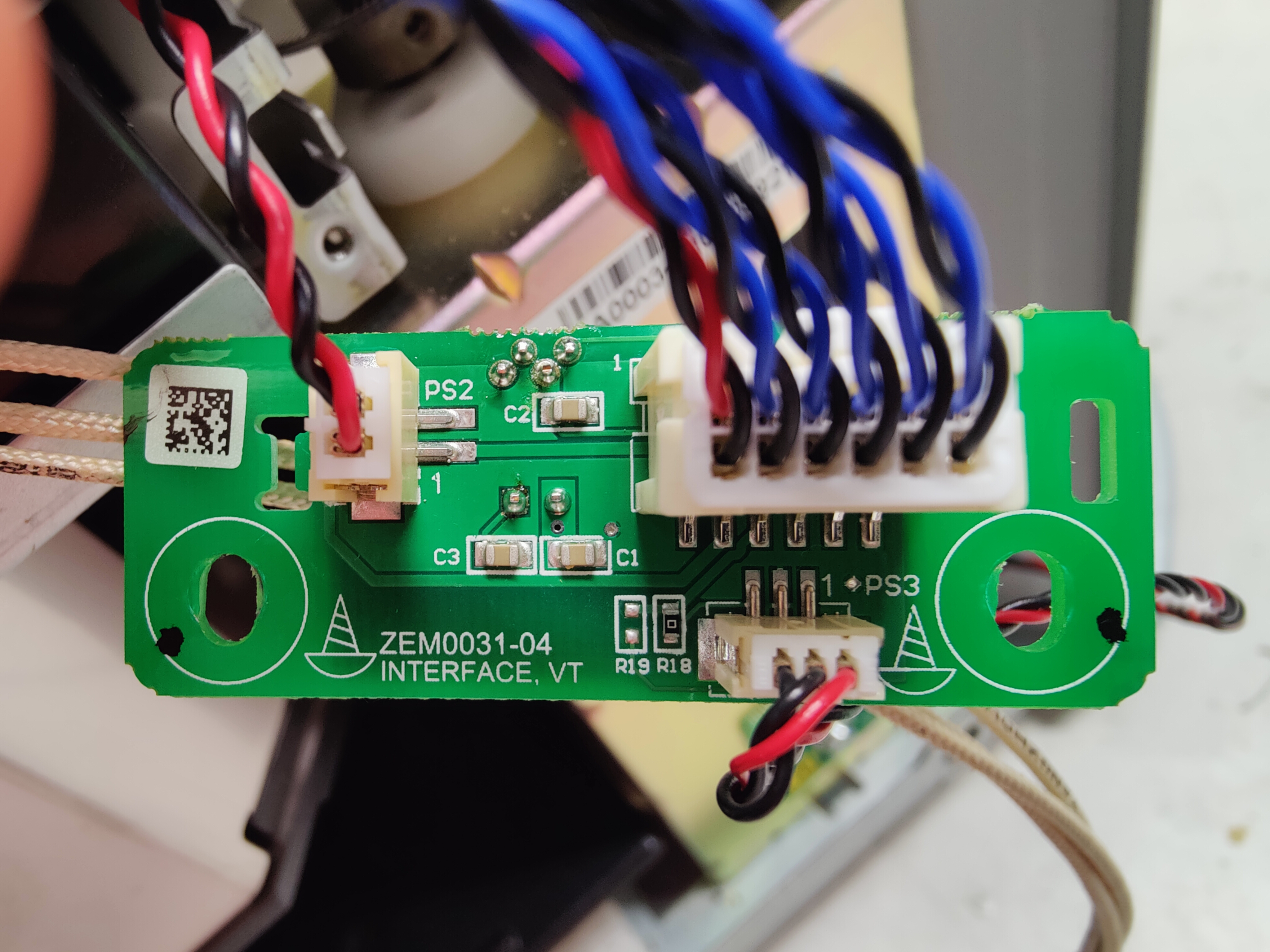
| 06:40, 7 September 2024 | Roti rotimatic infrared position sensor IC1 ZEM0031-04.jpg (file) |  |
6.38 MB | -.-6eau | Infrared (IR) position sensor "IC1" that optically reads marked disc connected to motor. Positioned above lower limit switch on front-right side of machine. ZEM0031-04 INTERFACE, VT | 1 |
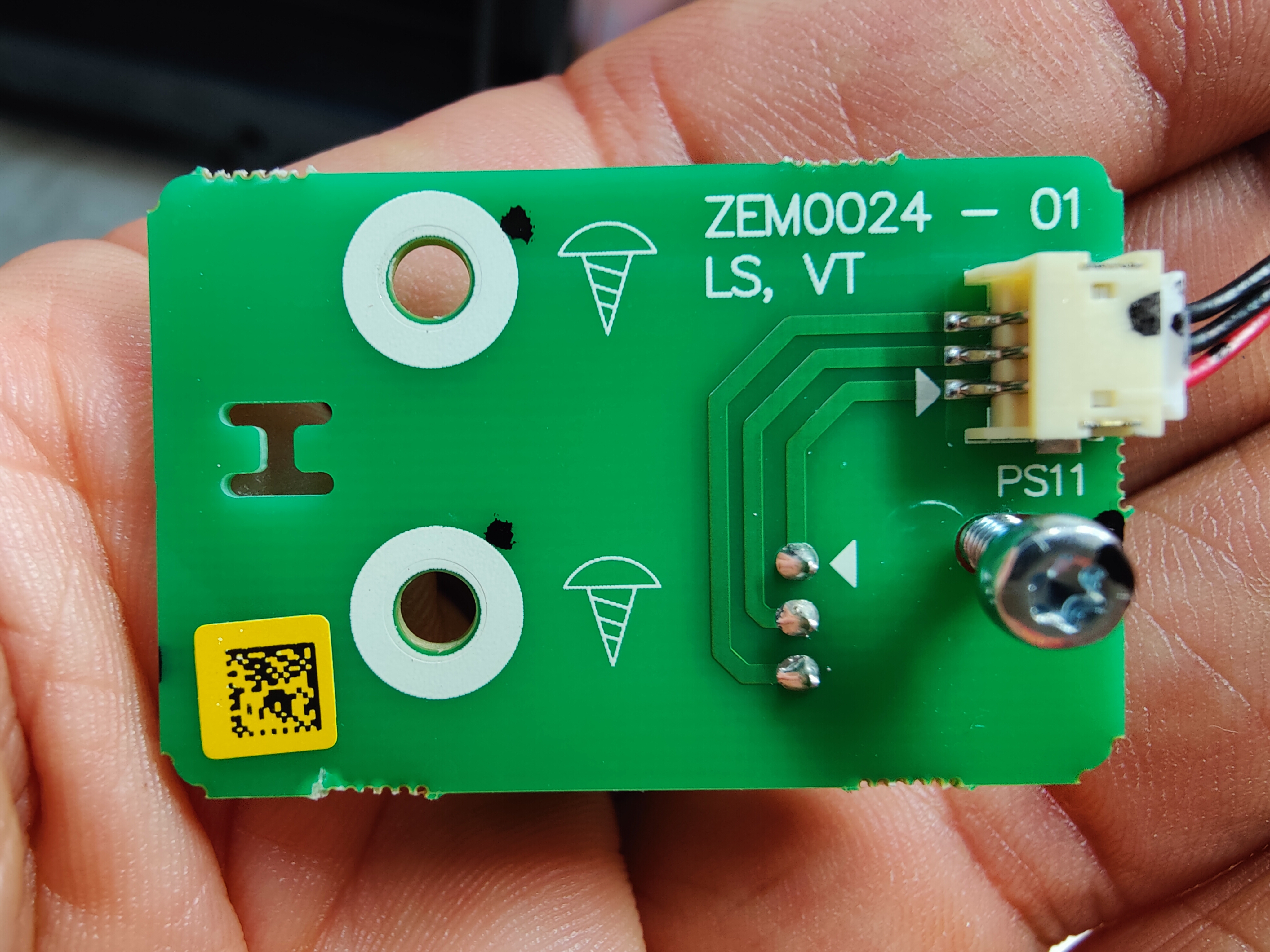
| 06:31, 7 September 2024 | Roti rotimatic ZEM0024-01 PCB .jpg (file) |  |
5.4 MB | -.-6eau | Back of lower limit switch PCB installed in front-right side of machine. 3 pin connector daisy chained to another sensor board. ZEM0024 - 01 LS, VT | 1 |
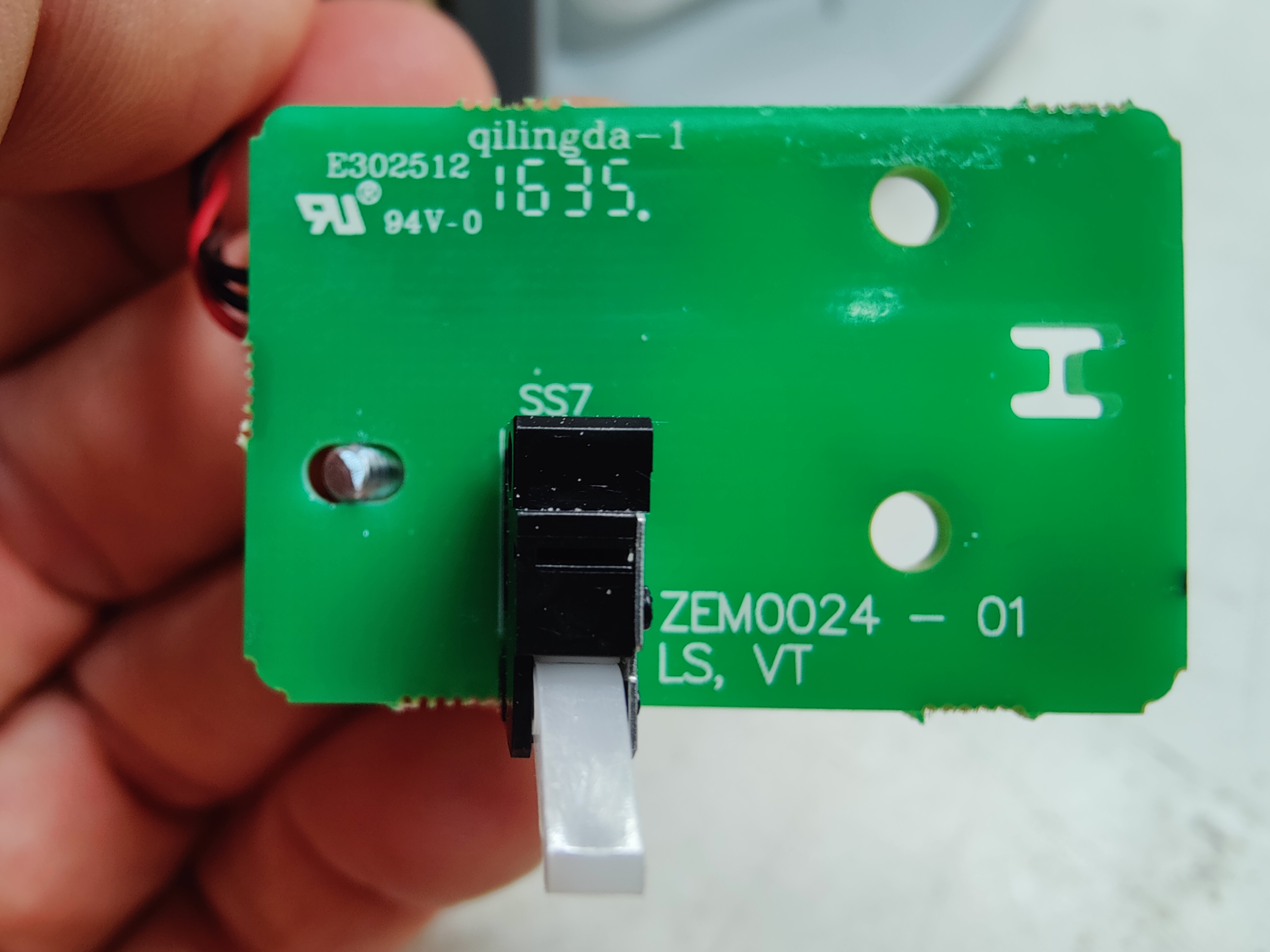
| 06:29, 7 September 2024 | Roti rotimatic ZEM0024-01 limit switch PCB.jpg (file) |  |
4.34 MB | -.-6eau | Lower limit switch installed on front-right side of machine. ZEM0024 - 01 LS, VT | 1 |
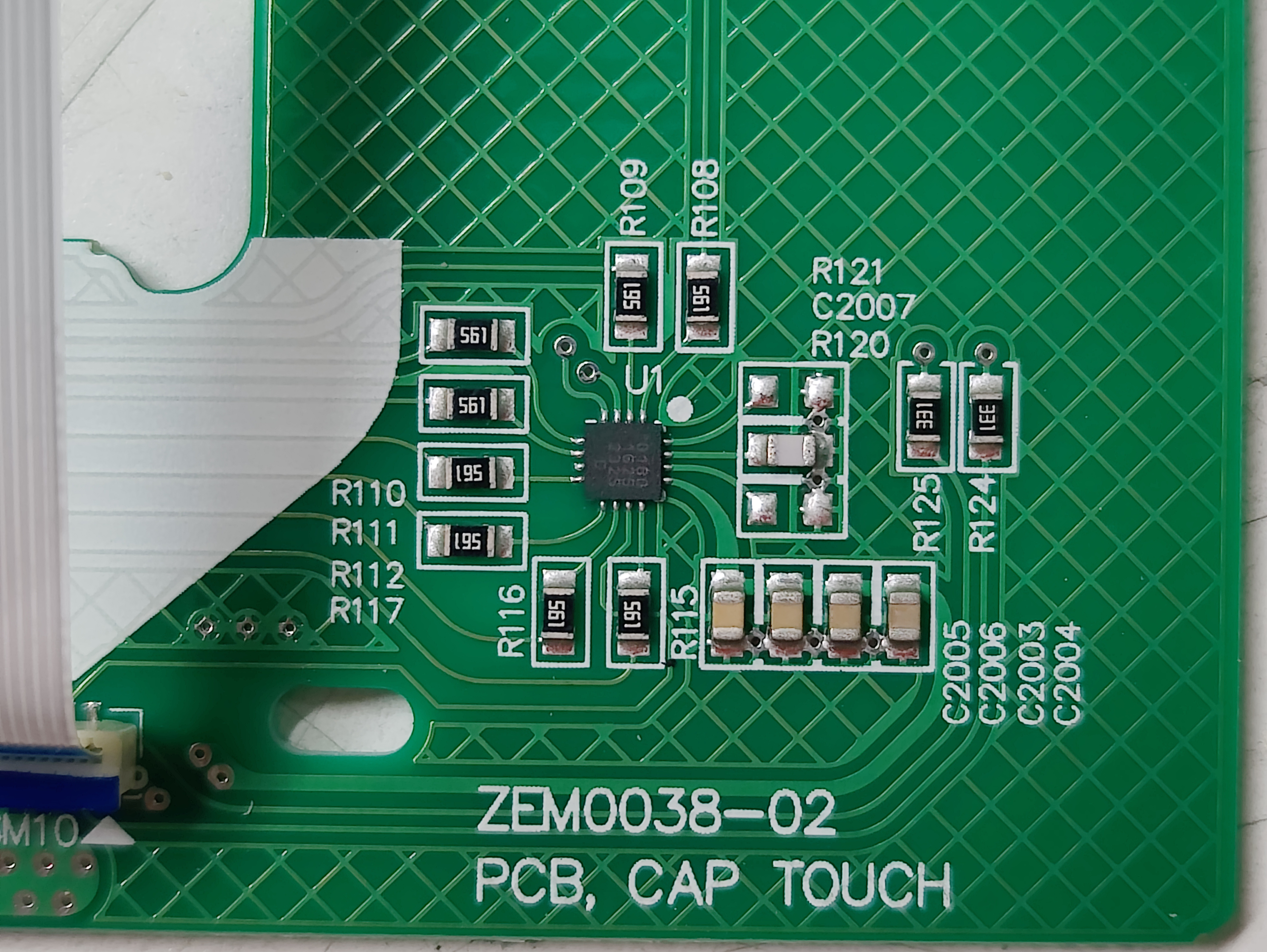
| 06:26, 7 September 2024 | Roti rotimatic capacitive touch IC.jpg (file) |  |
3.78 MB | -.-6eau | Close up of IC for capacitive touch input. Curved traces and bank of parallel capacitors. ZEM0038-02 PCB, CAP TOUCH | 1 |
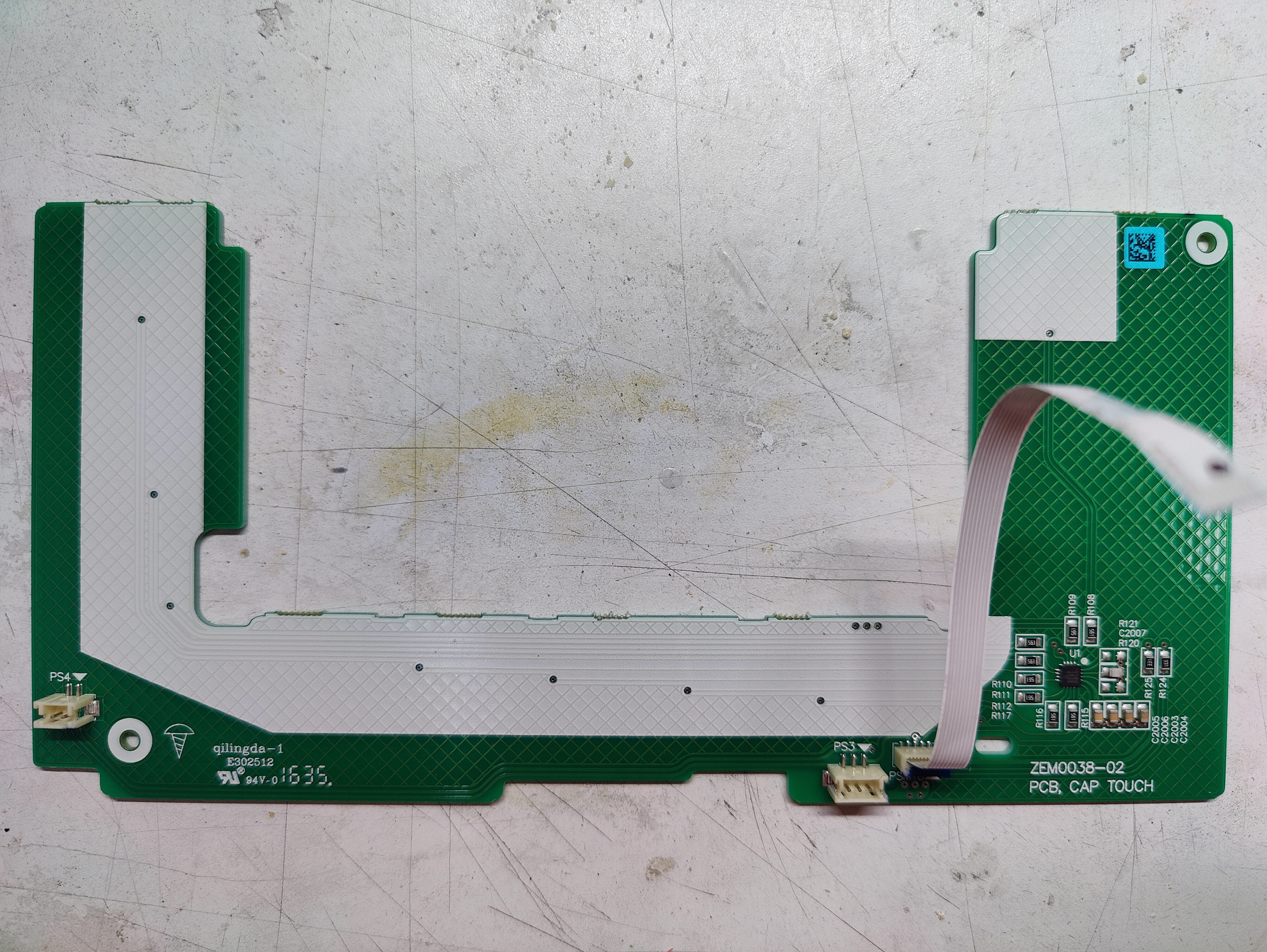
| 06:24, 7 September 2024 | Roti rotimatic capacitive touch PCB back.jpg (file) |  |
8.76 MB | -.-6eau | Reverse of capacitive touch board with 16 pin QFN controller chip and flex cable. ZEM0038-02 CAP TOUCH PCB | 1 |
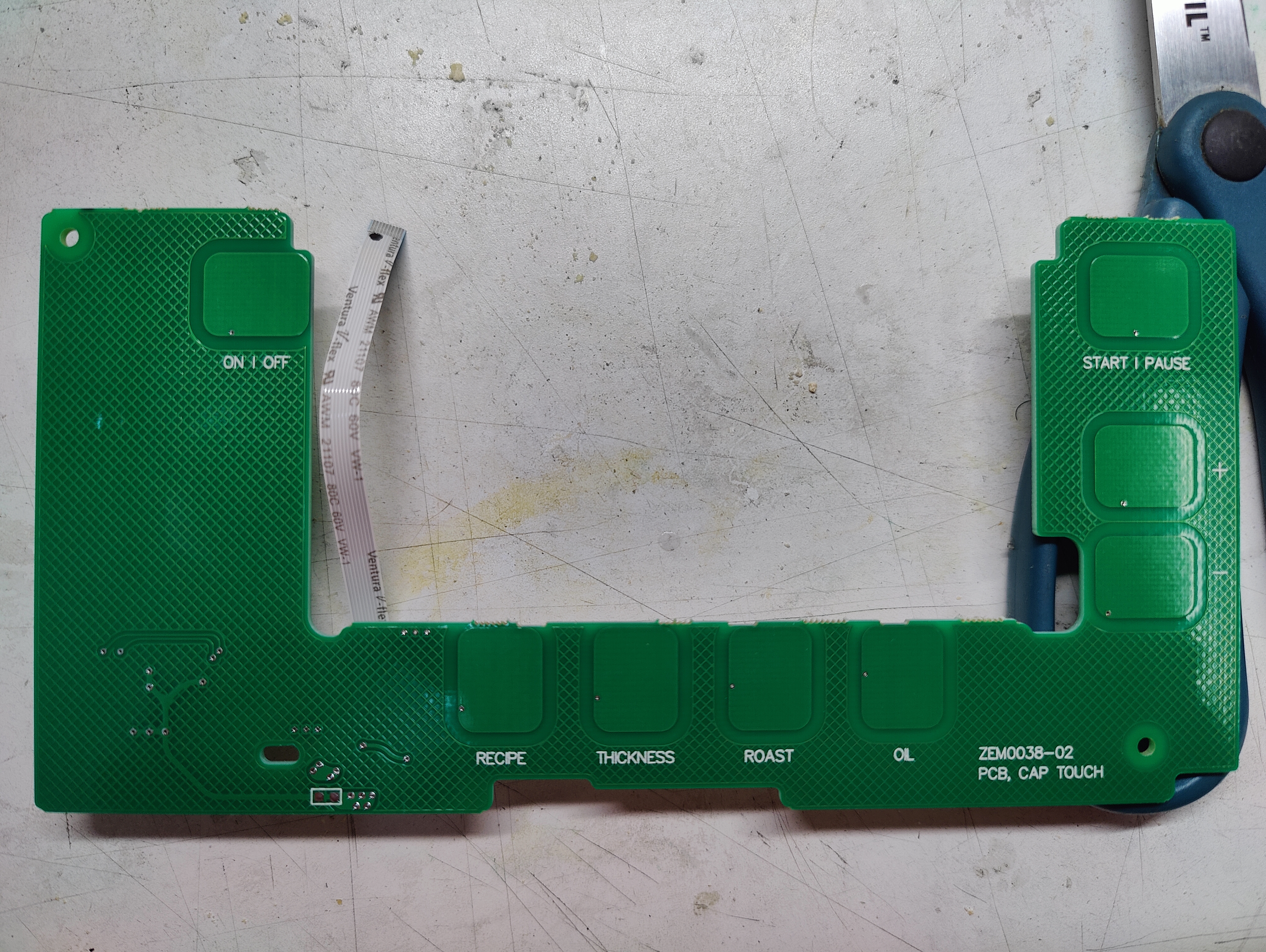
| 06:13, 7 September 2024 | Roti rotimatic capacitive touch PCB front.jpg (file) |  |
8.74 MB | -.-6eau | ZEM0038-02 CAP TOUCH PCB ON | OFF (Top Left) START | PAUSE (Right) RECIPE - THICKNESS - ROAST - OIL (BOTTOM) | 1 |
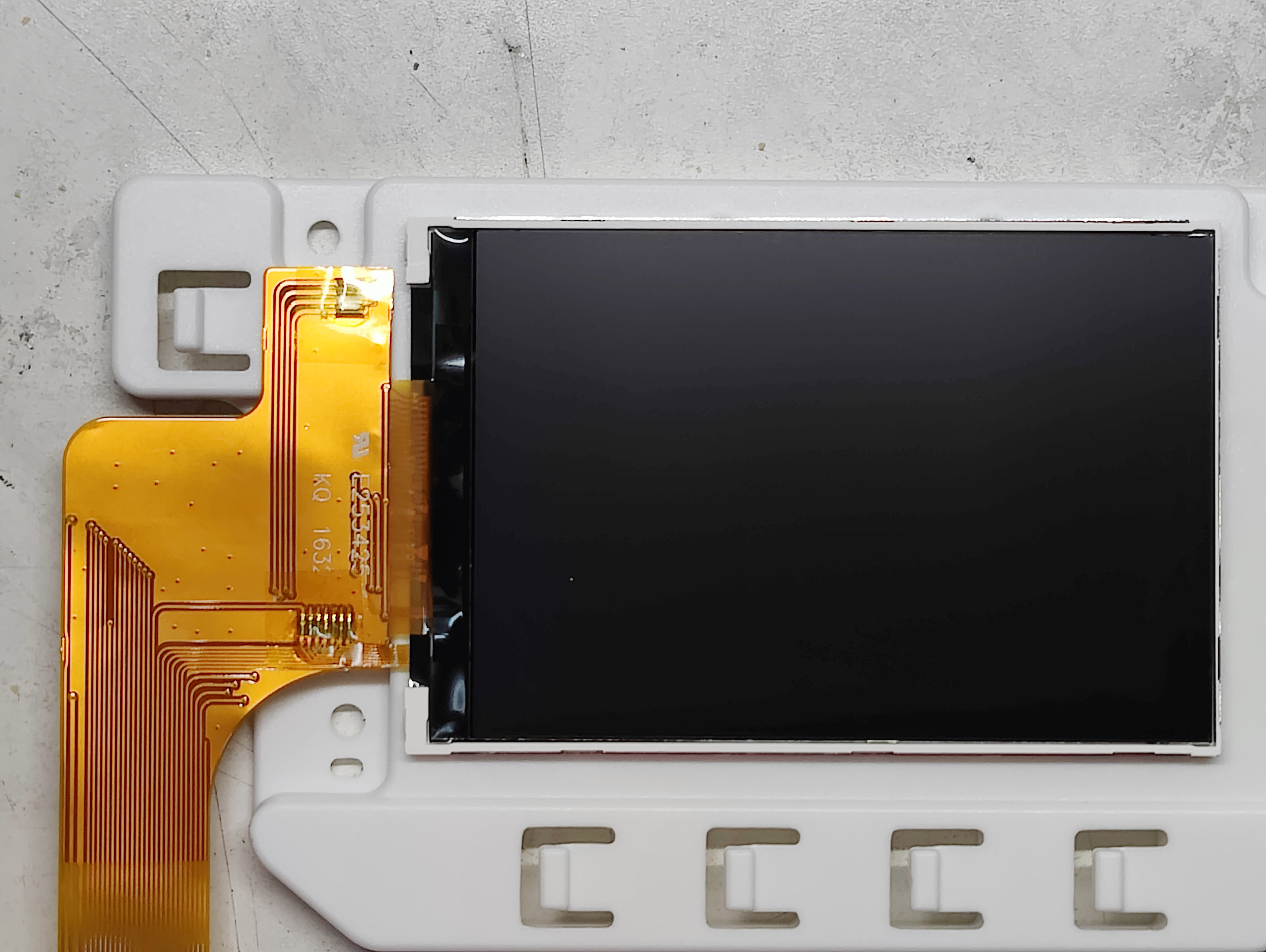
| 06:10, 7 September 2024 | Roti rotimatic LCD.jpg (file) |  |
2.31 MB | -.-6eau | LCD with flat flex used in main panel. The full display area is actually cropped with fully installed and portions of the edge of screen are not visible to the user. | 1 |
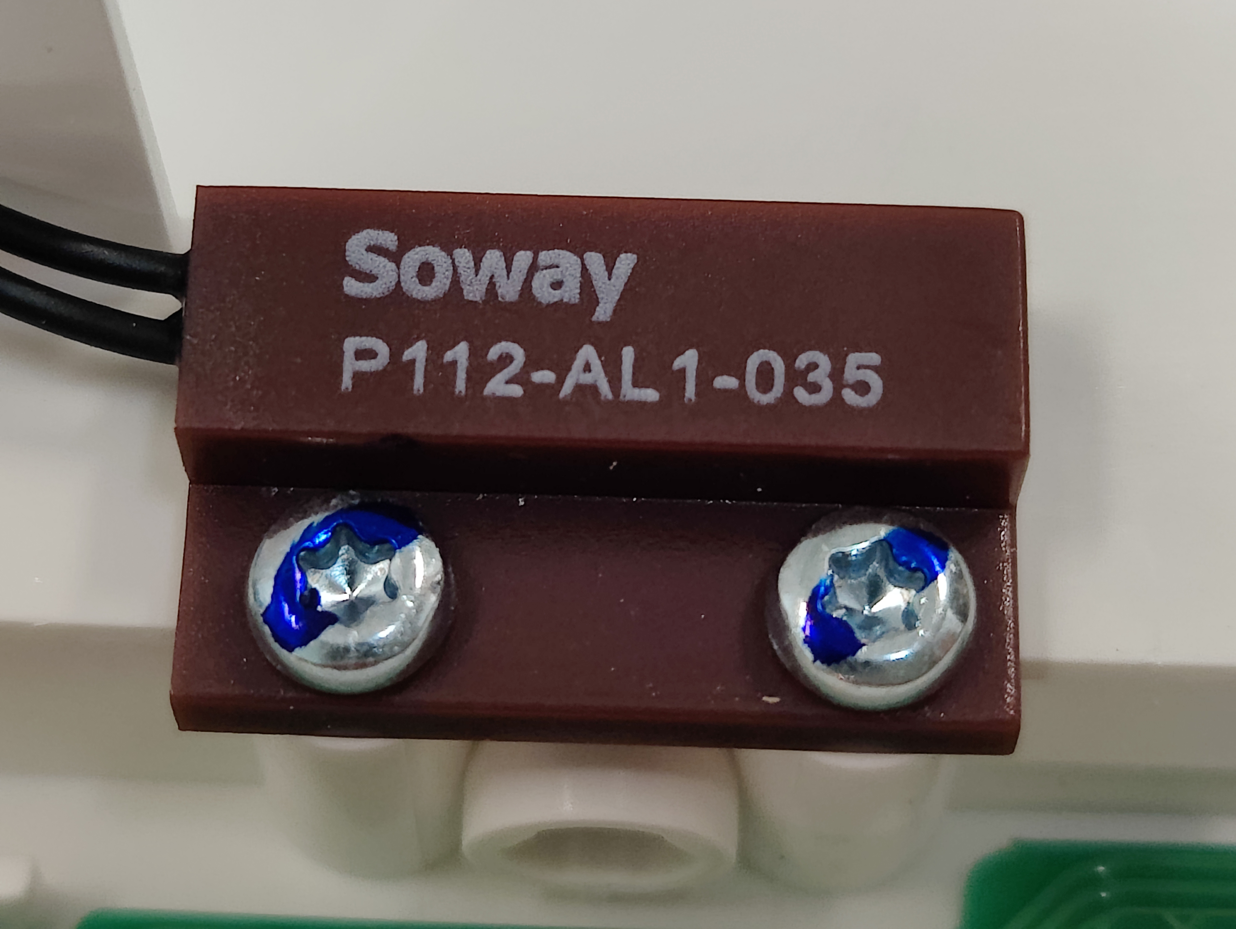
| 06:07, 7 September 2024 | Roti rotimatic Soway P112-AL1-035 sensor magnetic reed switch screwed.jpg (file) |  |
2.44 MB | -.-6eau | Magnetic non-contact reed switch attached with two torx screws. https://www.sowaytech.com/sdp/302911/4/pd-1125040/20969316-2310150/SP111-AL1-035_Soway_Magnetic_Sensor_Switch_Non-con.html | 1 |
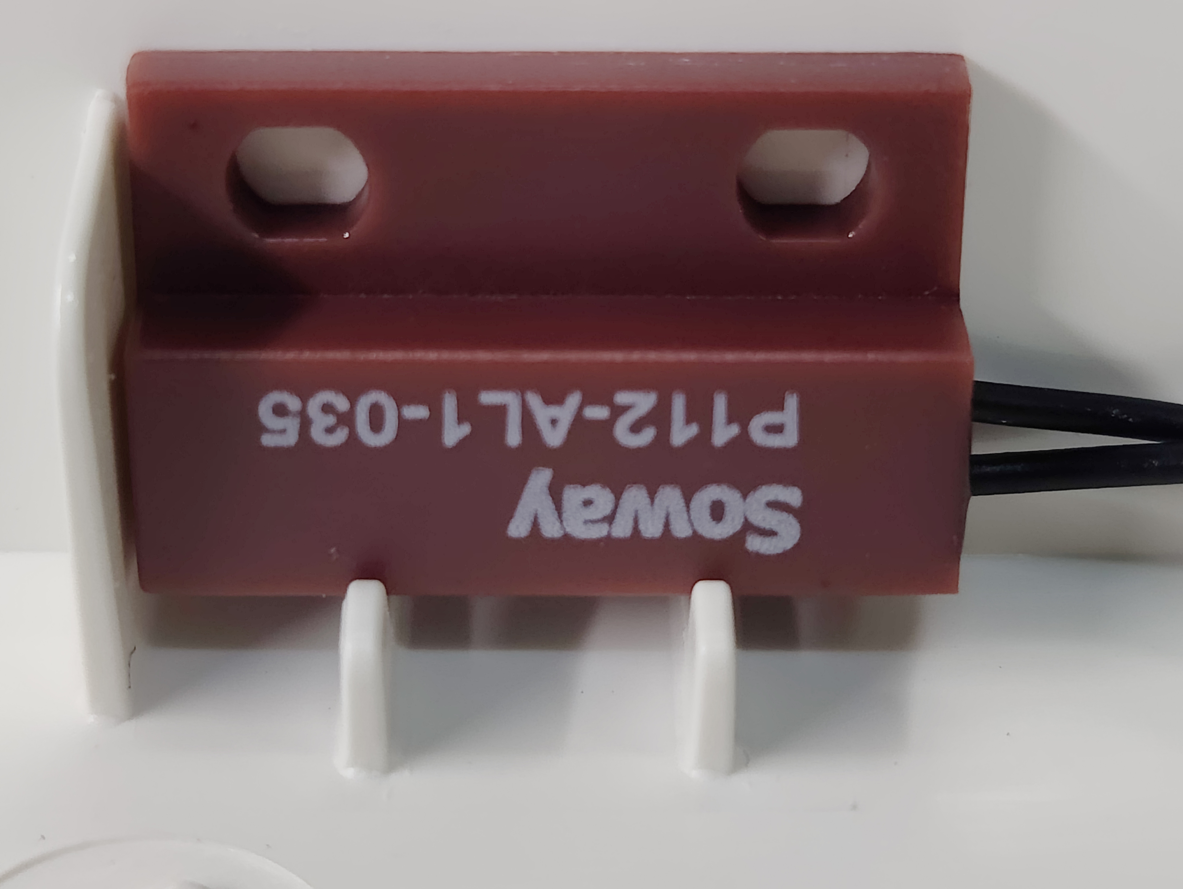
| 06:05, 7 September 2024 | Roti rotimatic Soway P112-AL1-035 sensor magnetic reed switch.jpg (file) |  |
1.85 MB | -.-6eau | Magnetic non-contact reed switch attached with adhesive. https://www.sowaytech.com/sdp/302911/4/pd-1125040/20969316-2310150/SP111-AL1-035_Soway_Magnetic_Sensor_Switch_Non-con.html | 1 |
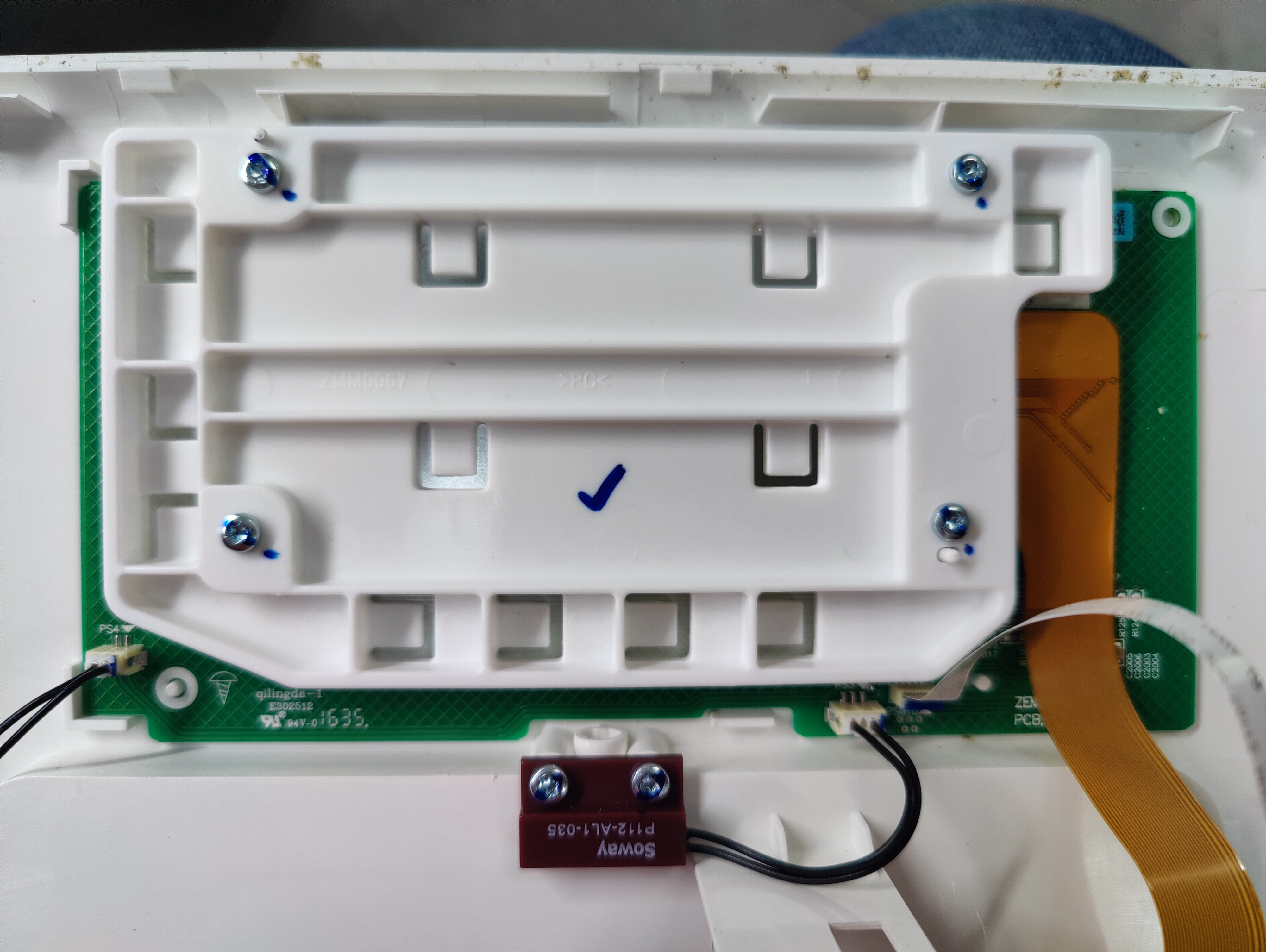
| 06:00, 7 September 2024 | Roti rotimatic front panel back.jpg (file) |  |
5.77 MB | -.-6eau | Main panel LCD and capacitive touch button assembly. Attached with 4 torx screws. One of two door closed sensors shown, PS4 connection on left goes to second sensor. | 1 |
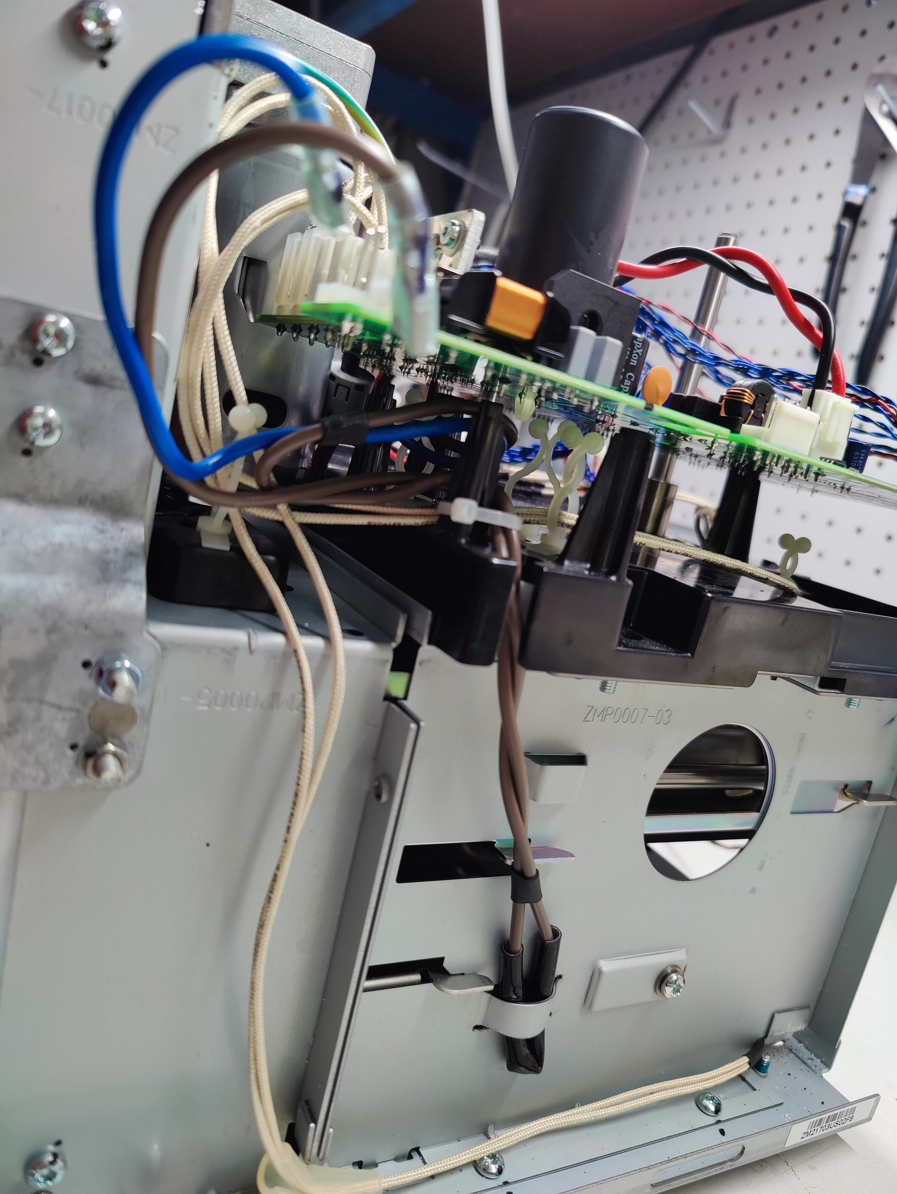
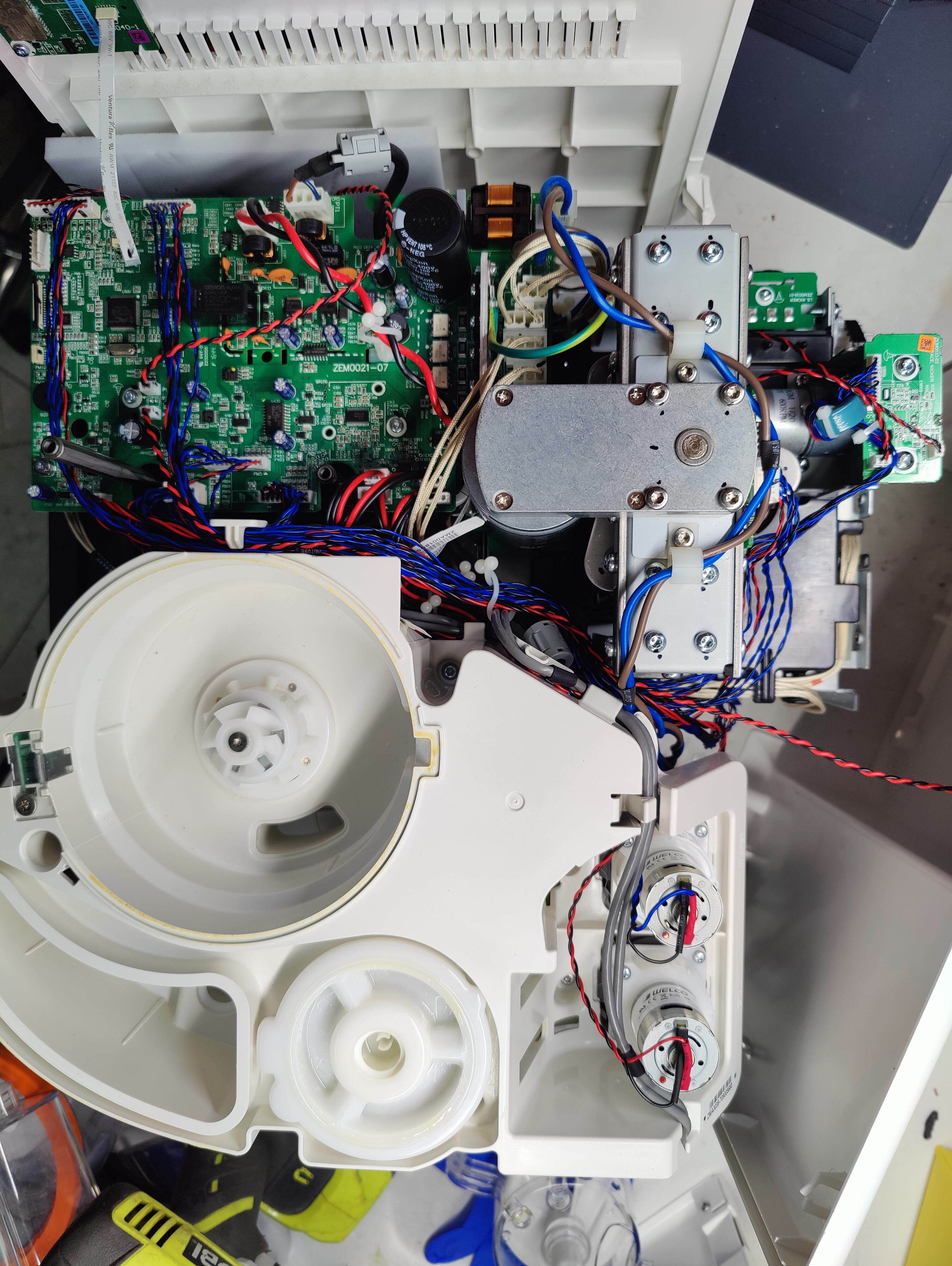
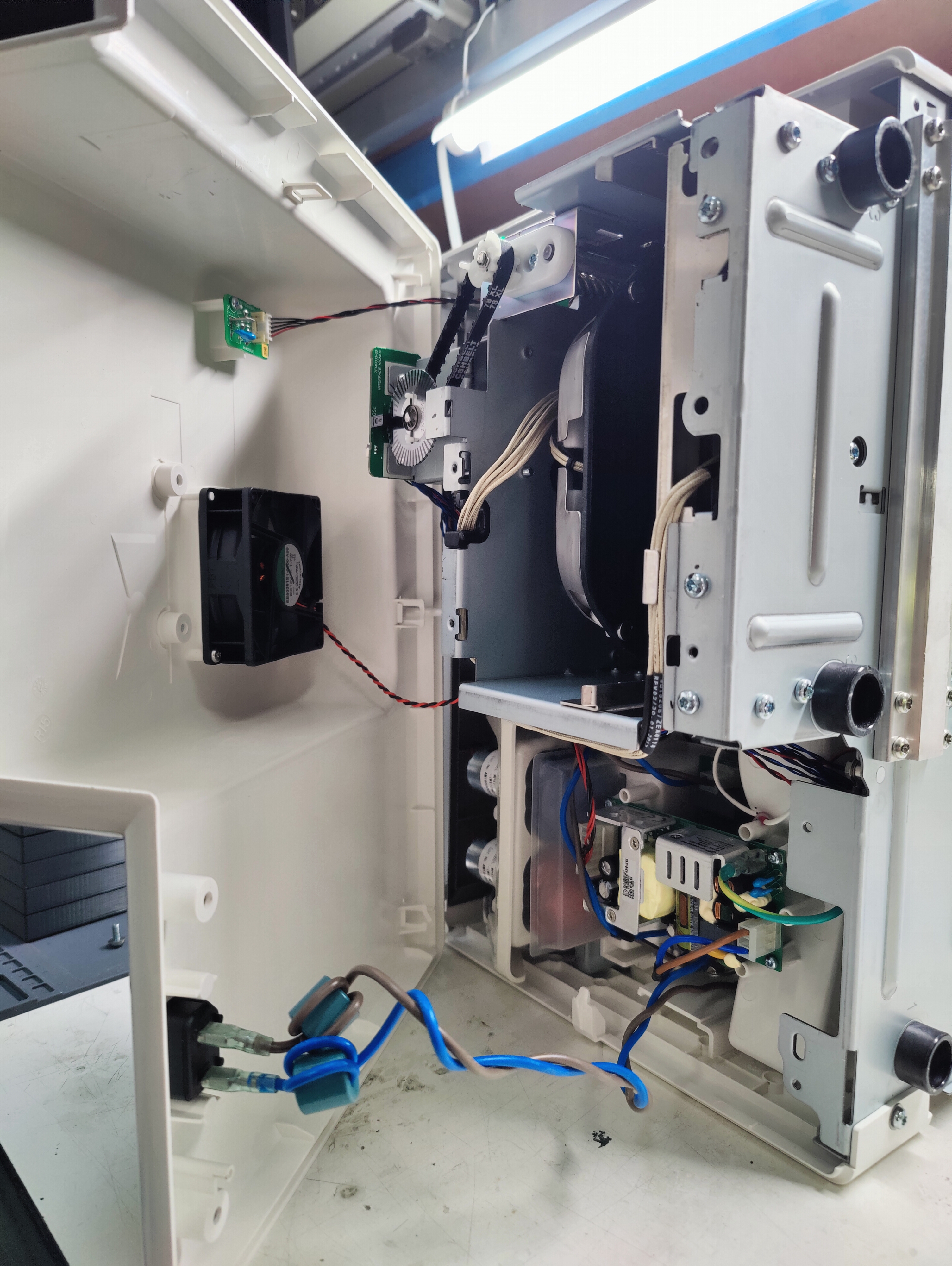
| 05:53, 7 September 2024 | Roti rotimatic top no cover.jpg (file) |  |
7.15 MB | -.-6eau | View of entire machine from the top with cover, front and back panels removed. Note side panel with wireless module flat flex at top left. 2 twisted pairs of red/black wires connecting in lower middle left of main board. Upper pair goes to side panel. Lower pair goes to rear fan (right side of picture). Front panel screen flex connector towards top of left edge of board, next to buttons flat flex just below it. Two mains pairs of AC wires brown/blue independently routed one directly to right... | 1 |
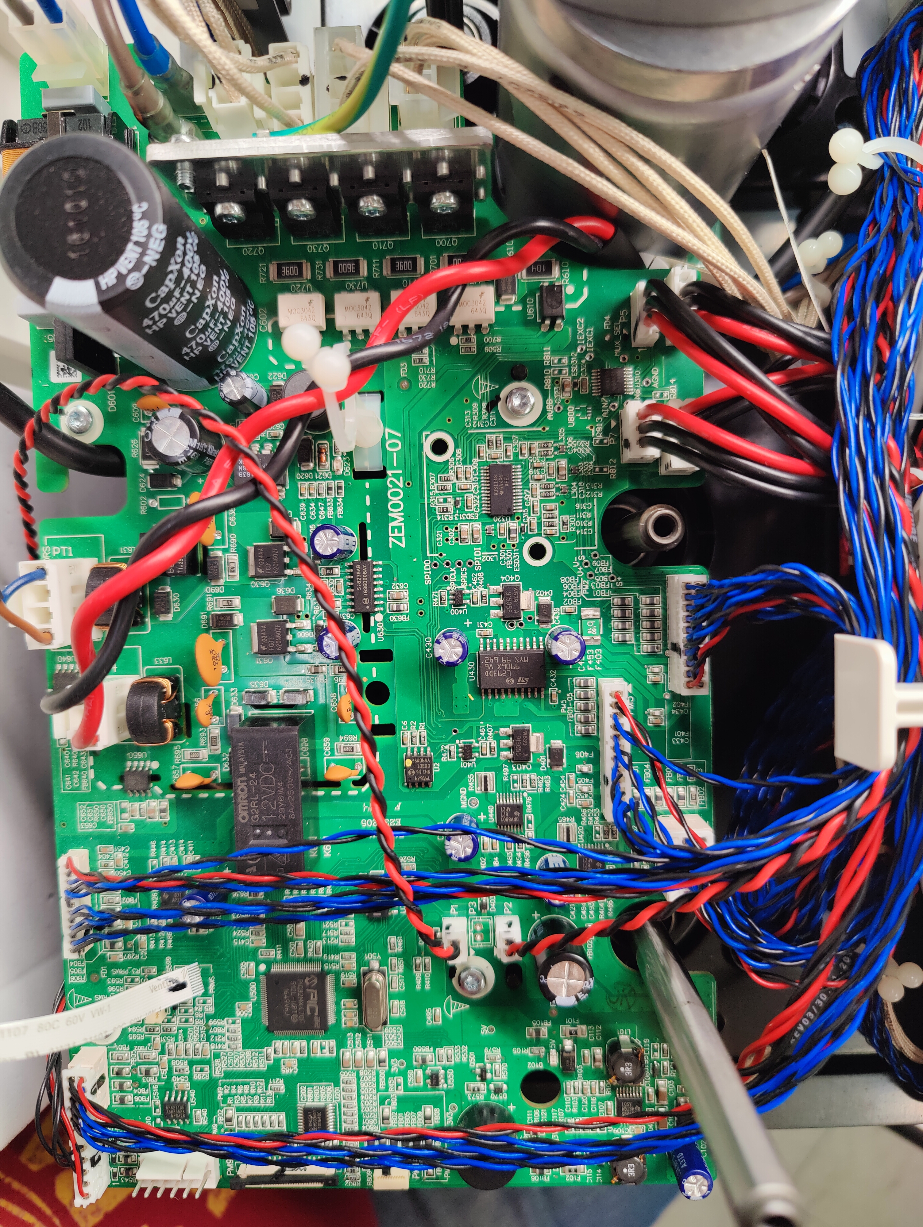
| 05:38, 7 September 2024 | Roti rotimatic main board PIC32MX470F512L.jpg (file) |  |
8.92 MB | -.-6eau | PCB: ZEM0021-07 PIC32MX470F512L-I/PT MIPS32® M4K™ PIC® 32MX Microcontroller IC 32-Bit Single-Core 80MHz 512KB (512K x 8) FLASH 100-TQFP (12x12) | 1 |
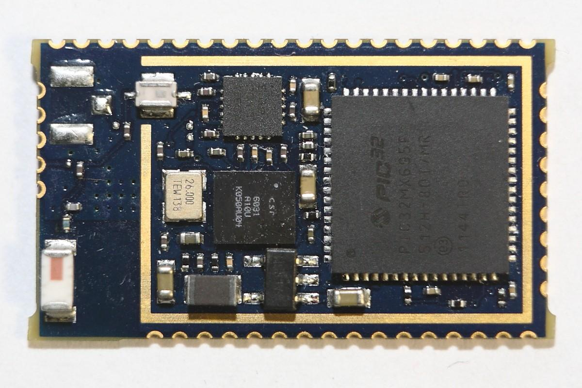
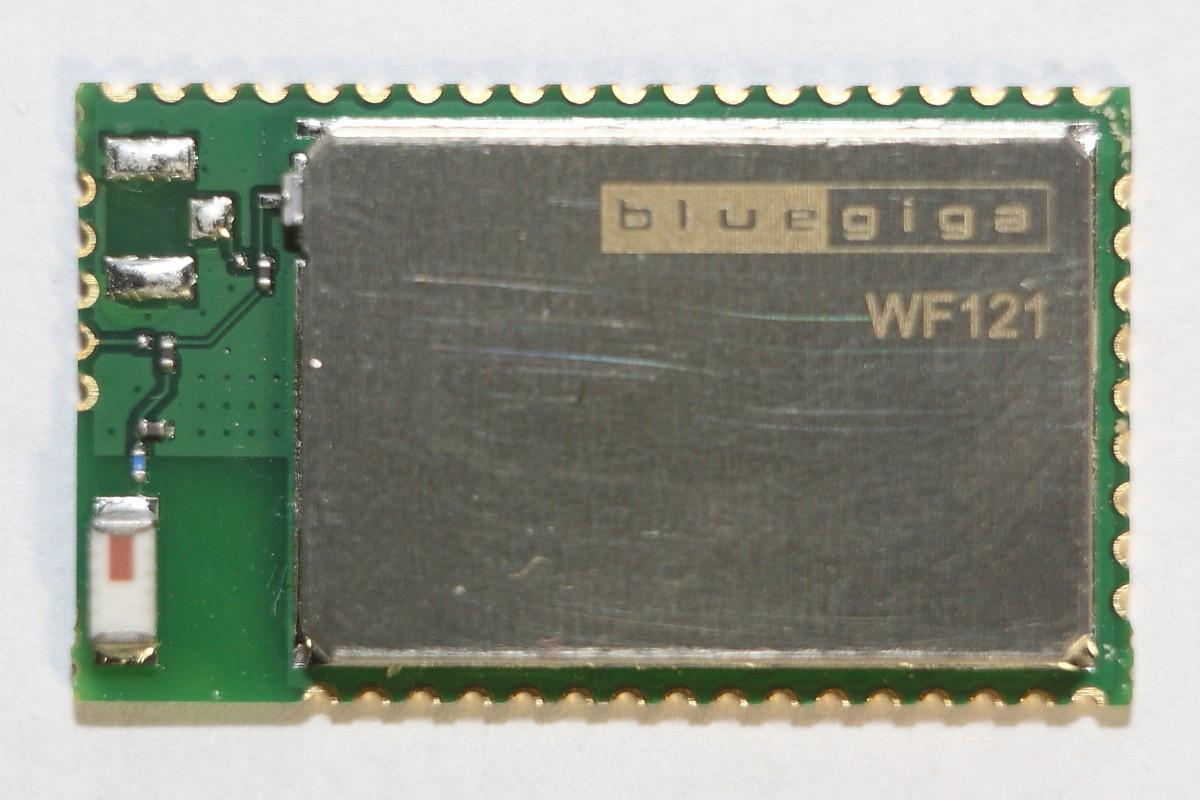
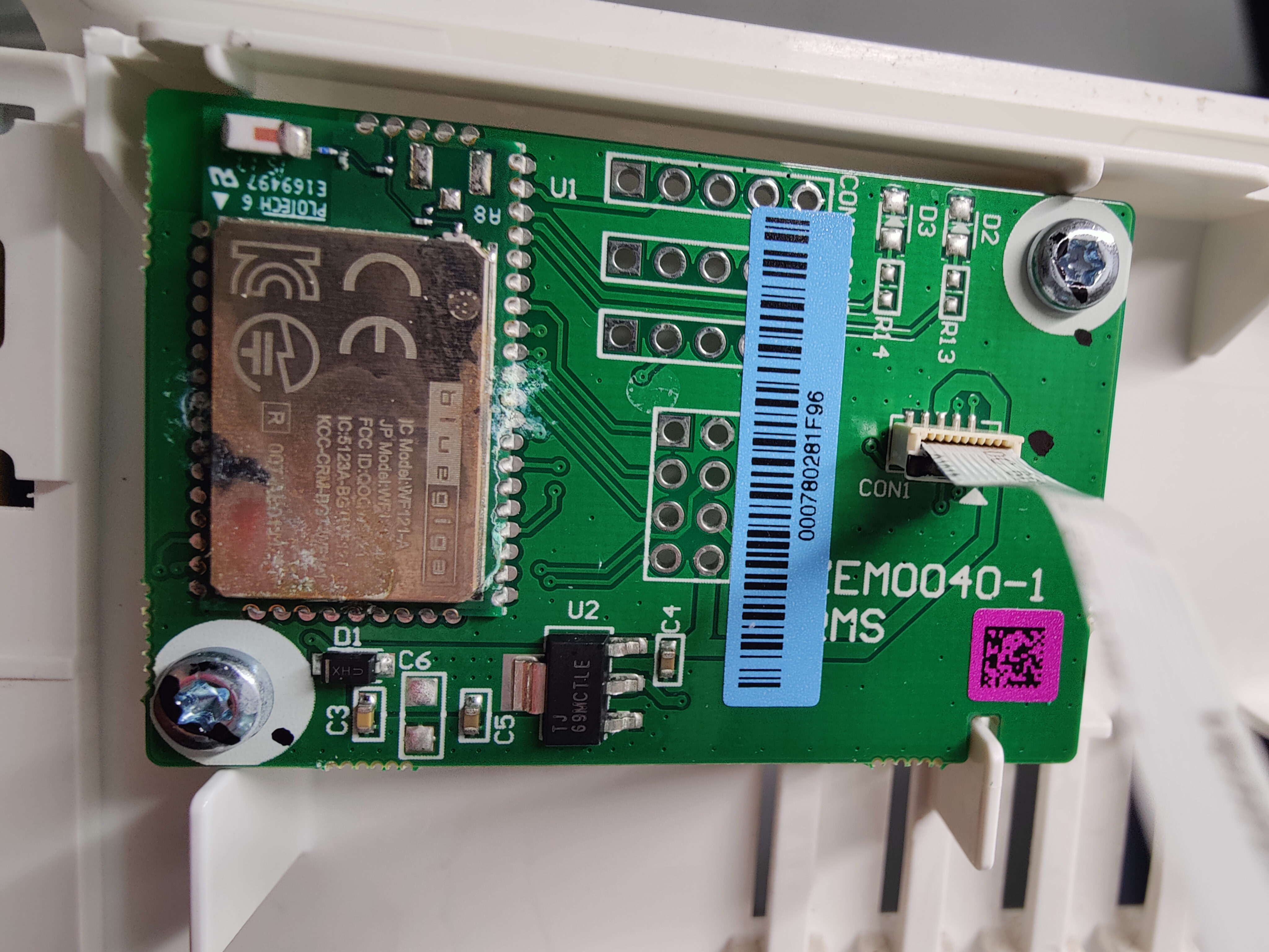
| 05:33, 7 September 2024 | Roti rotimatic bluegiga WF121-A.jpg (file) |  |
6.06 MB | -.-6eau | Wireless board with 802.11 b/g/n bluegiga module and flat flex connector. | 1 |
| 05:29, 7 September 2024 | Roti rotimatic under rear cover.jpg (file) |  |
5.97 MB | -.-6eau | Opening rear cover after popping plastic latches and removing T20 screw from bottom. Fan wiring passes to connector on top of main board, one of two. Upper board with 5 wires is external USB connector, presumably for thumb stick to reflash firmware. 2 wire AC mains, brown and blue with ferrites. Not shown reset-able 2 prong plug for connecting to outlet. | 1 |