Uploads by Trevor229
This special page shows all uploaded files.
| Date | Name | Thumbnail | Size | Description | Versions |
|---|---|---|---|---|---|
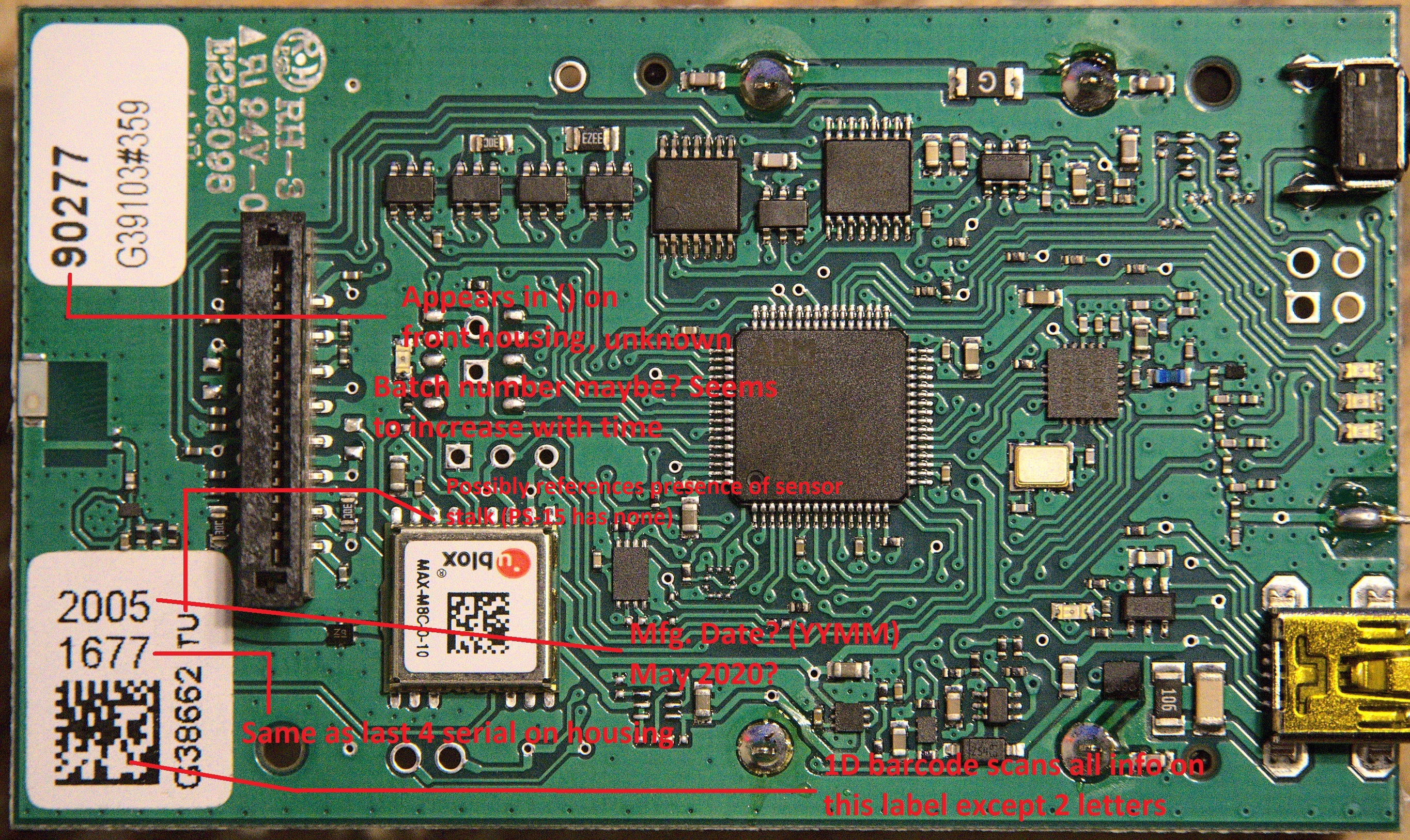
| 03:06, 14 December 2022 | Label id speculaton.jpg (file) |  |
3.16 MB | 1 | |
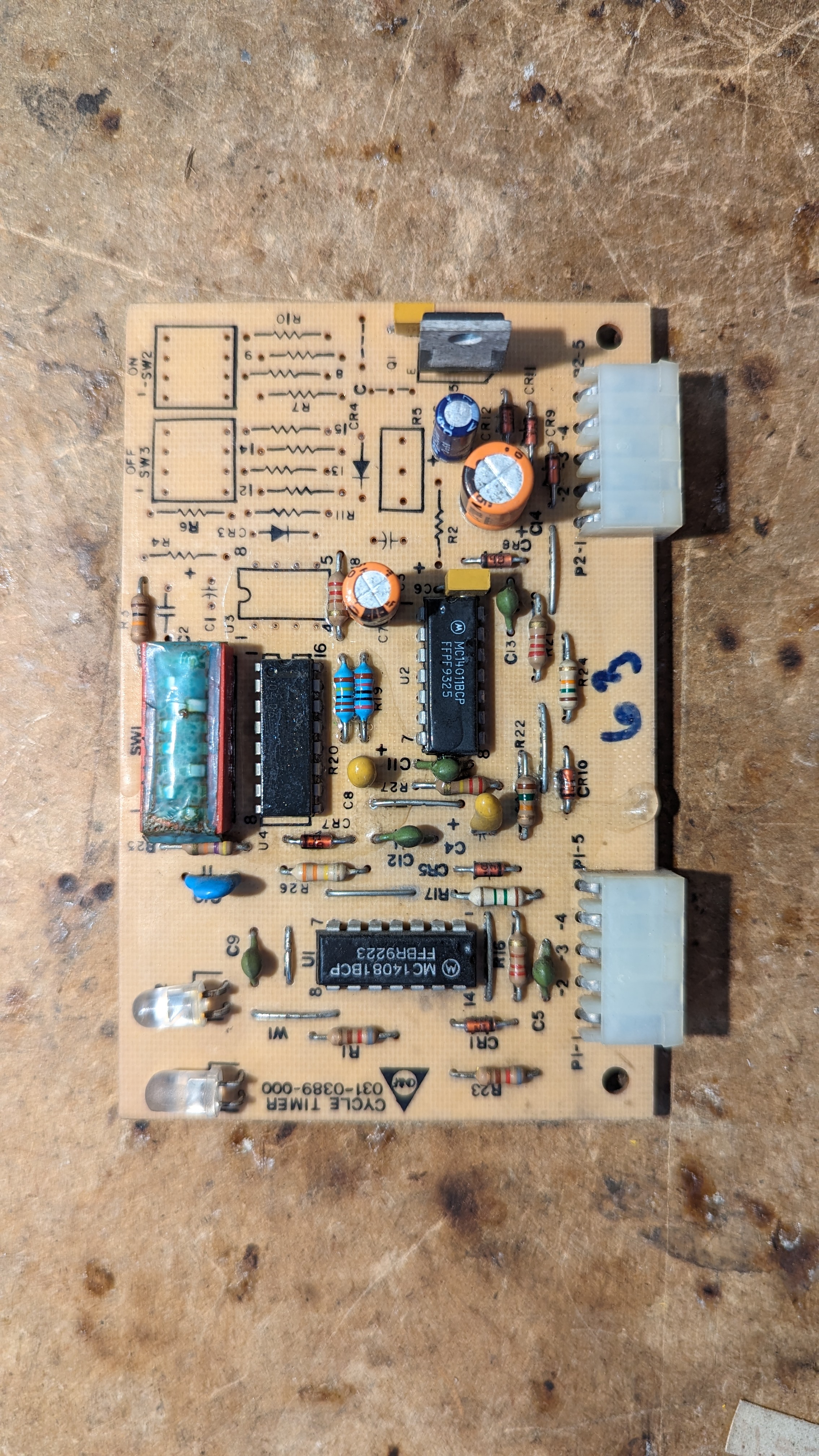
| 00:09, 17 April 2024 | Cdf cycle timer front.jpg (file) |  |
2.58 MB | Cycle timer (Steady) front from the CD&F | 1 |
| 00:50, 17 January 2023 | Dfm 17 swd and resistors.jpg (file) |  |
2.43 MB | 1 | |
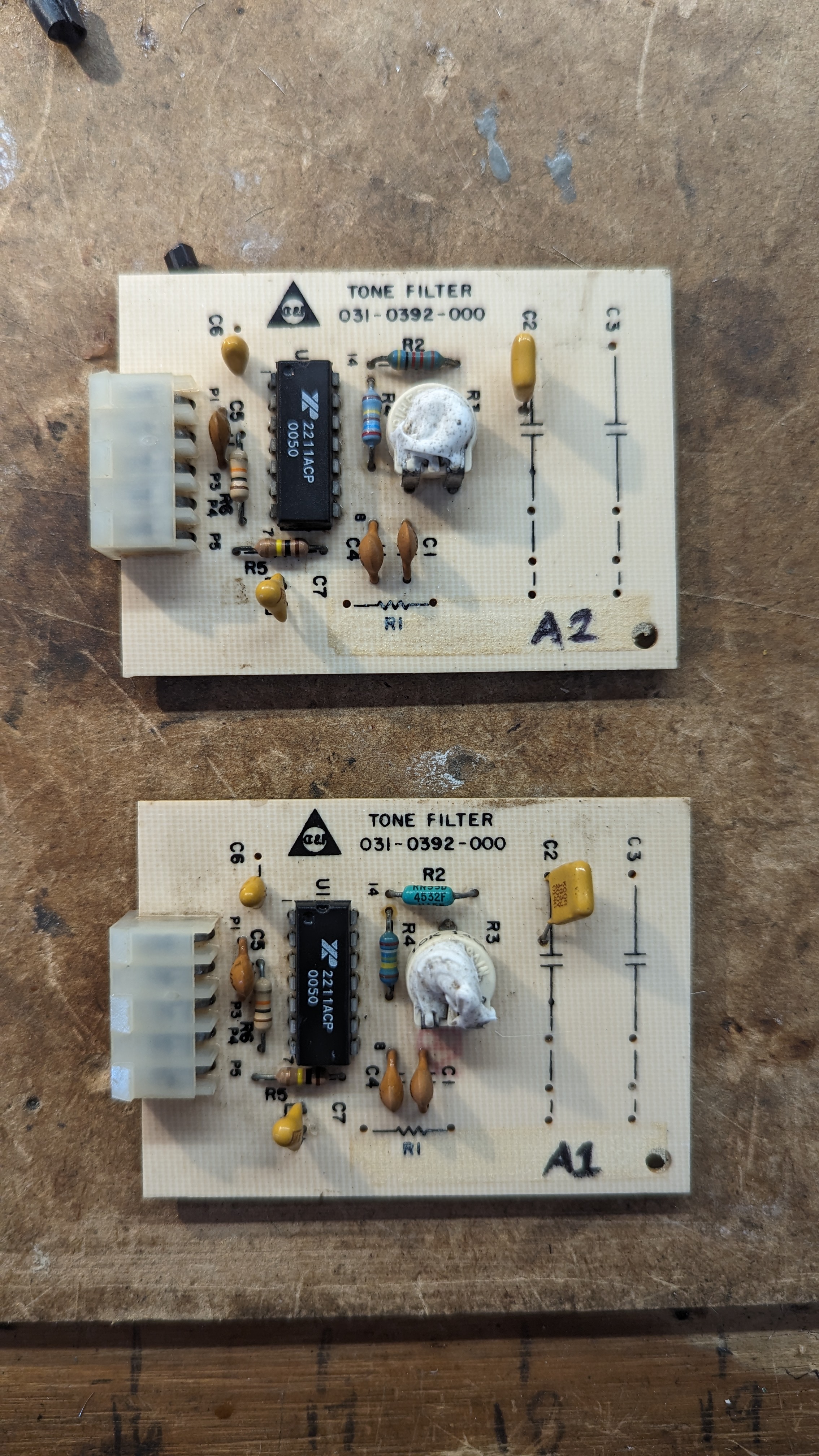
| 23:02, 15 April 2024 | Cdf filters top.jpg (file) |  |
2.31 MB | Top view of both CD&F tone decoder modules | 1 |
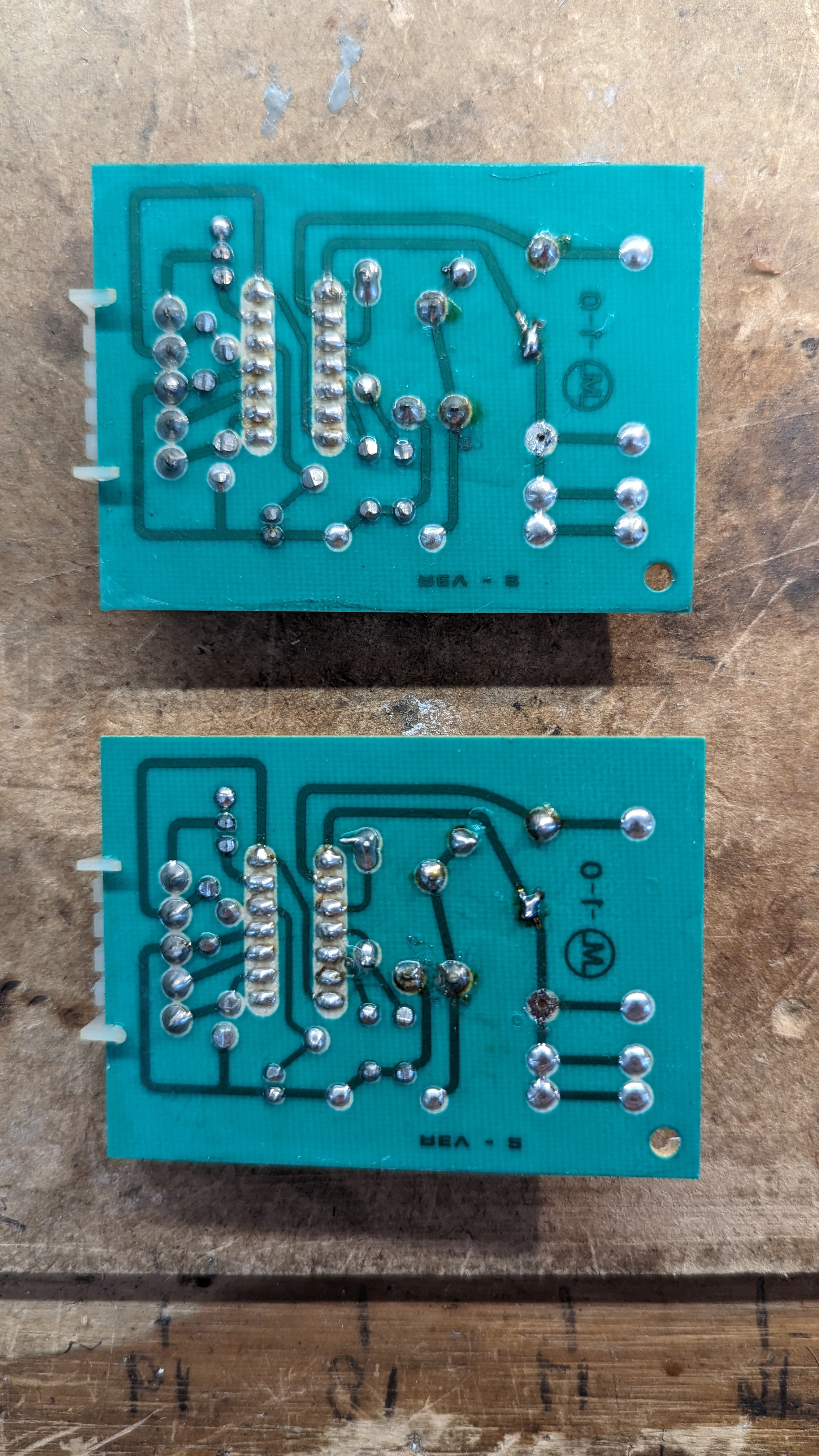
| 23:03, 15 April 2024 | Cdf filters bottom.jpg (file) |  |
2.29 MB | Bottom side of the CD&F tone filter modules. Mirrored to match the top side. | 1 |
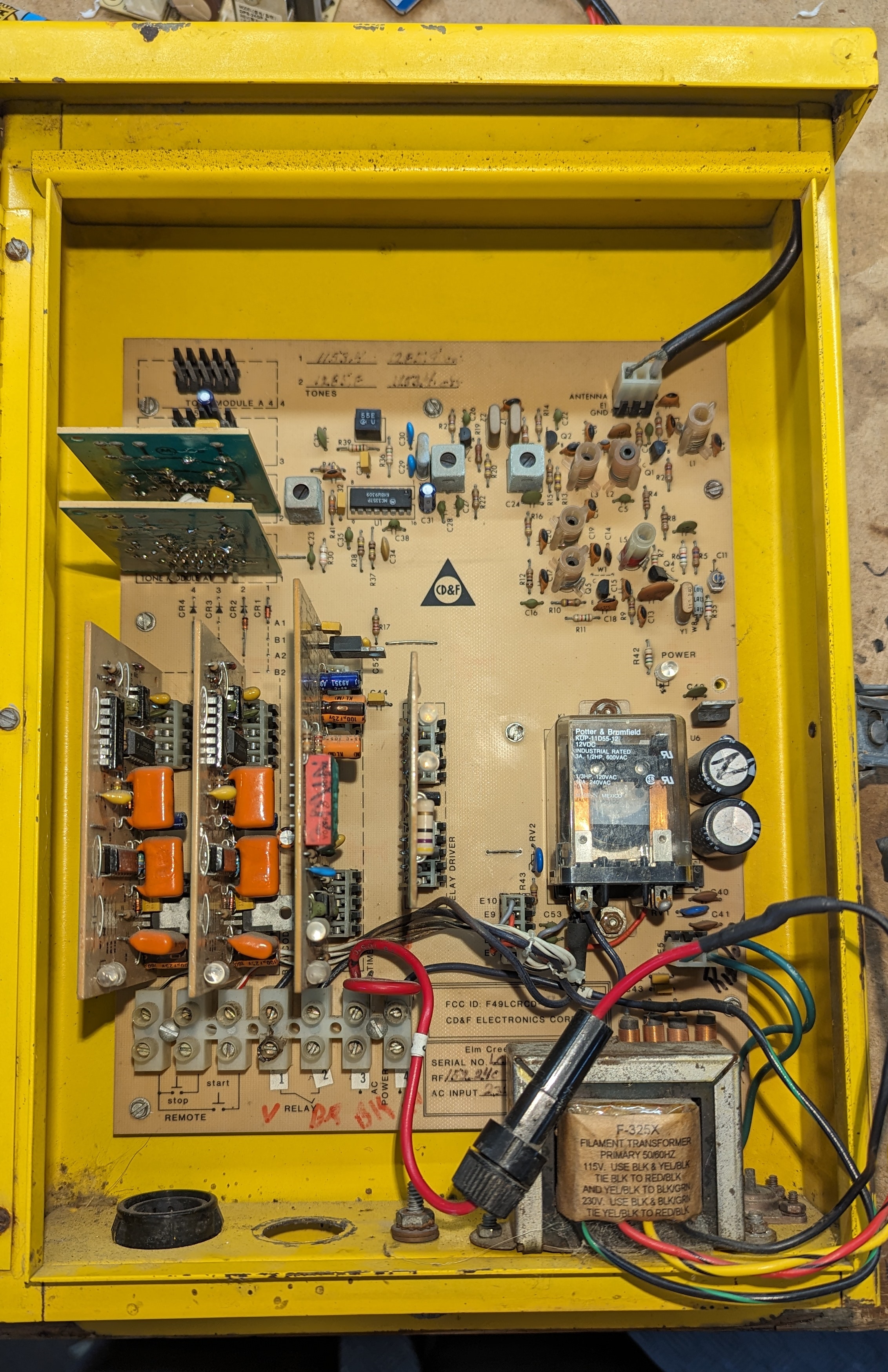
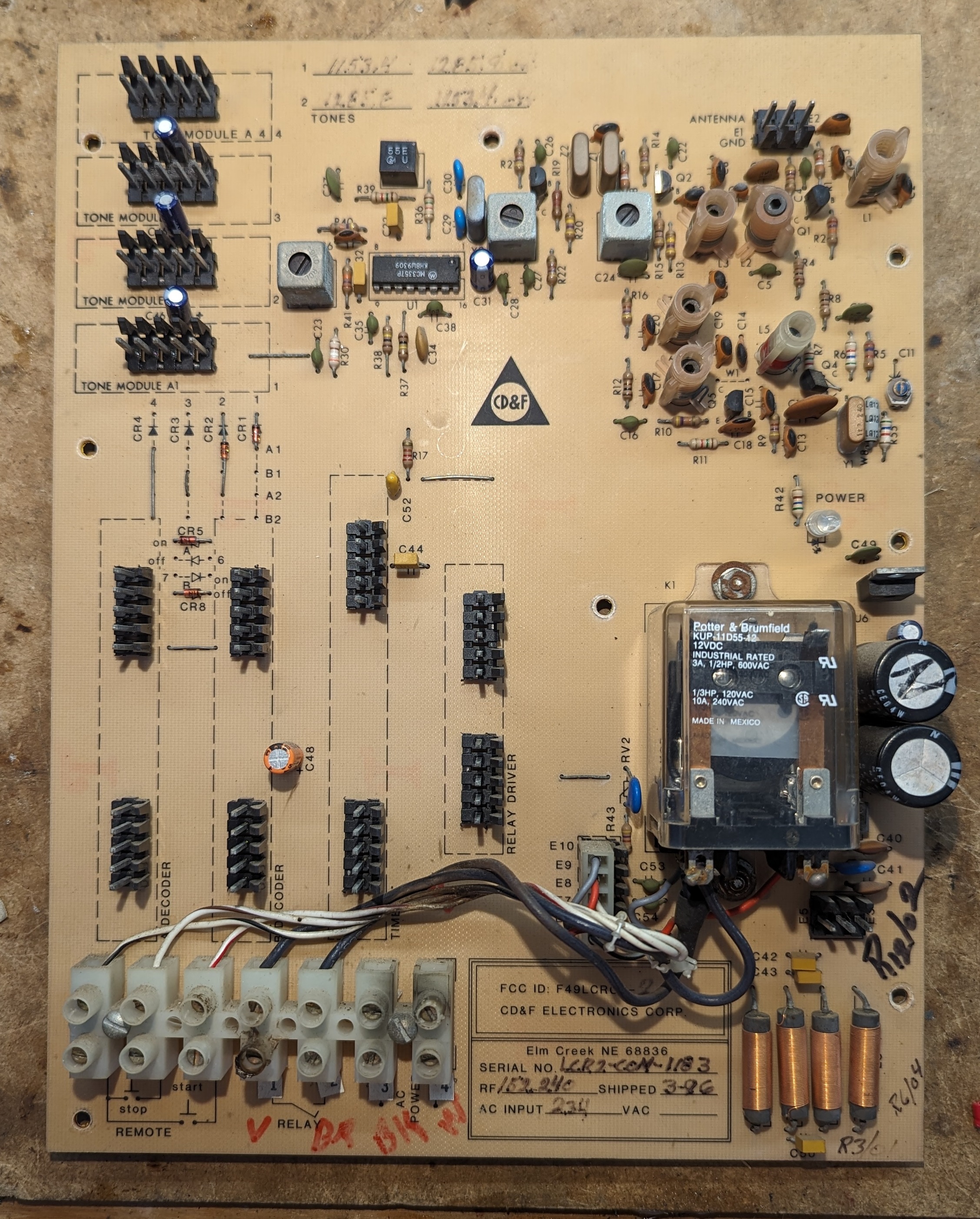
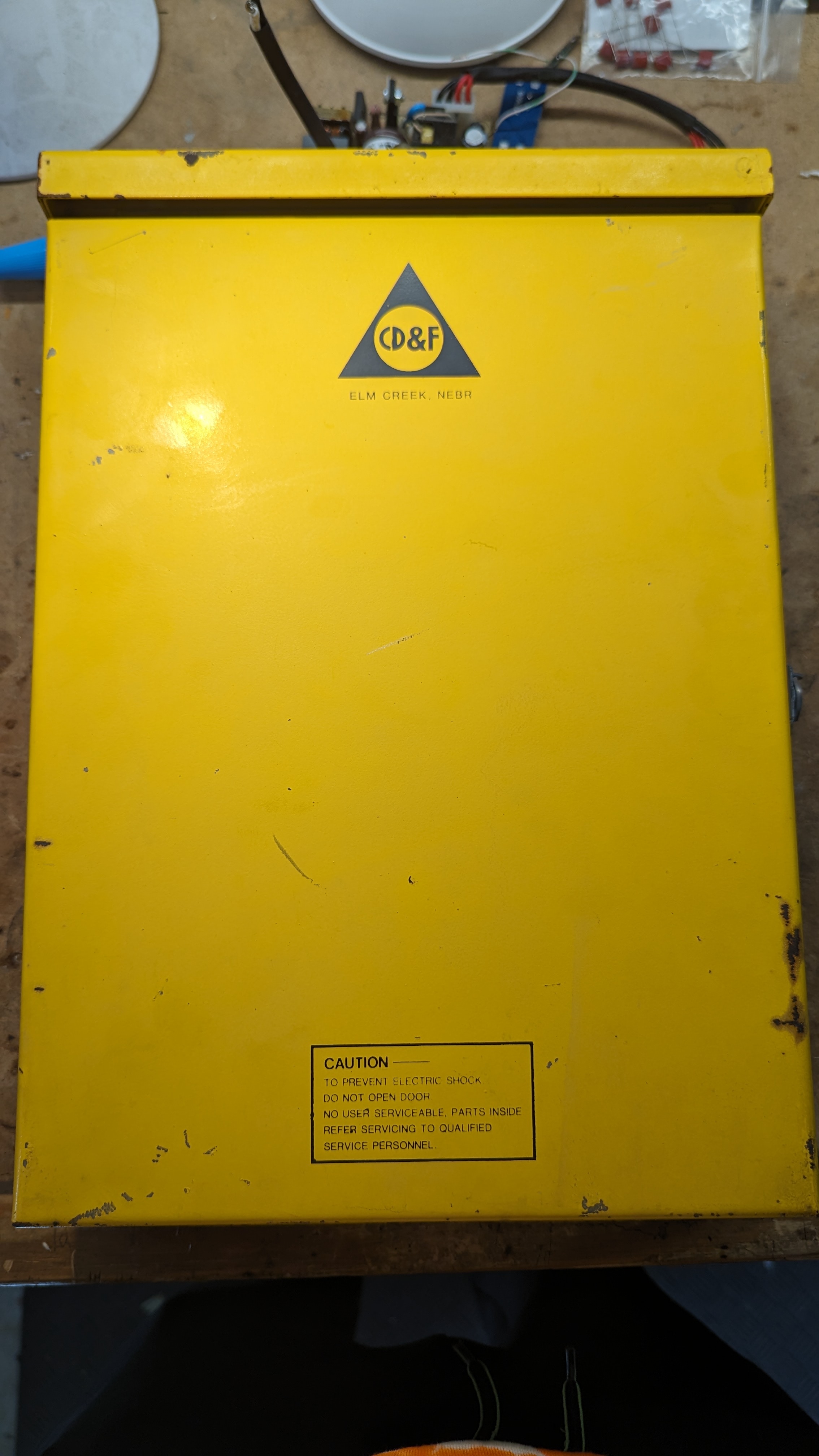
| 05:42, 15 April 2024 | Cdf front open.jpg (file) |  |
2.28 MB | CD&F controller with the front door open | 1 |
| 23:23, 15 April 2024 | Cdf rx closeup back.jpg (file) |  |
2.15 MB | Closeup of the rear of the double conversion super heterodyne radio receiver circuitry in the CD&F. Mirrored to match Cdf_rx_closeup.jpg | 1 |
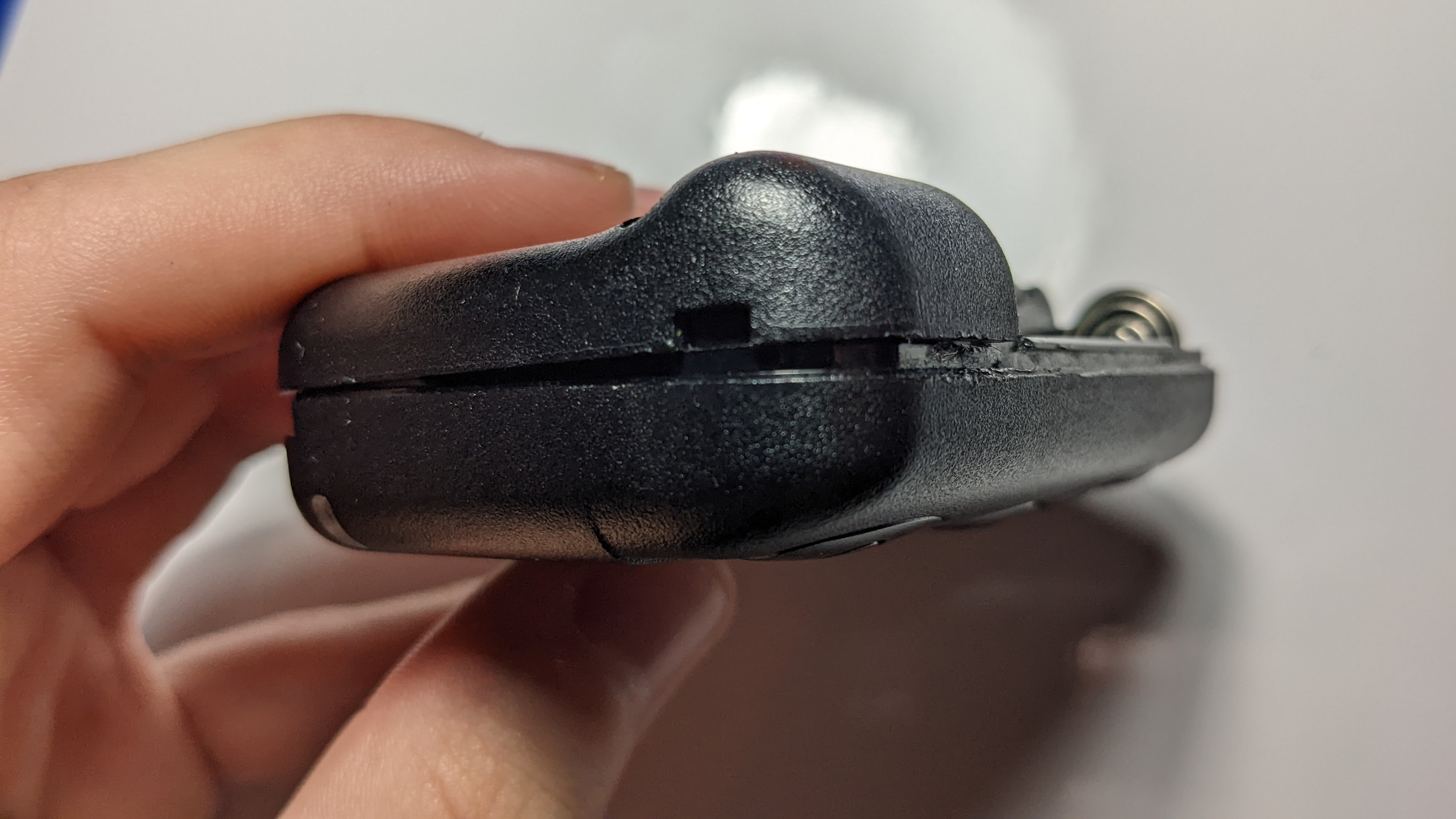
| 04:37, 24 April 2022 | Align top tabs pager.jpg (file) |  |
2.03 MB | 1 | |
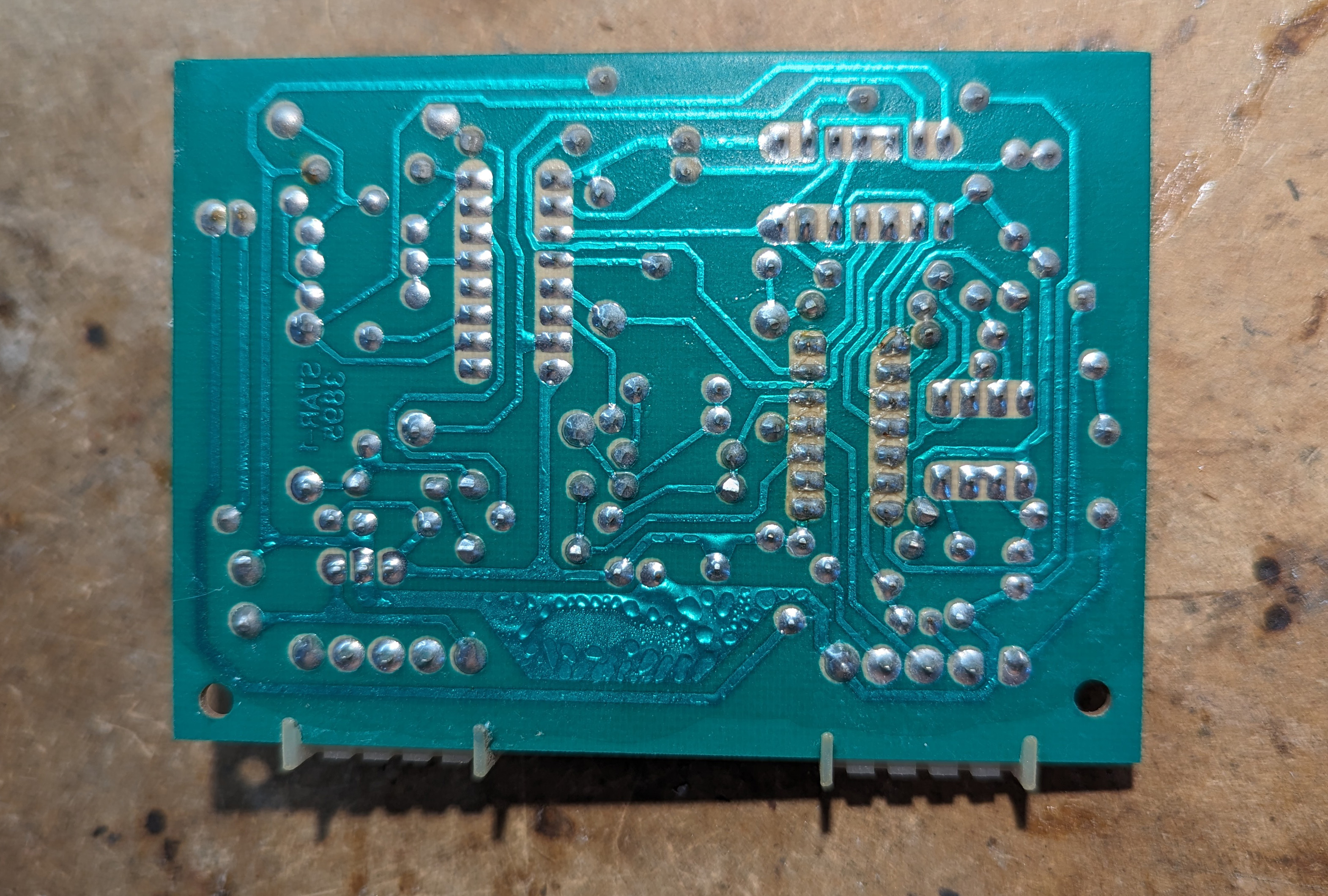
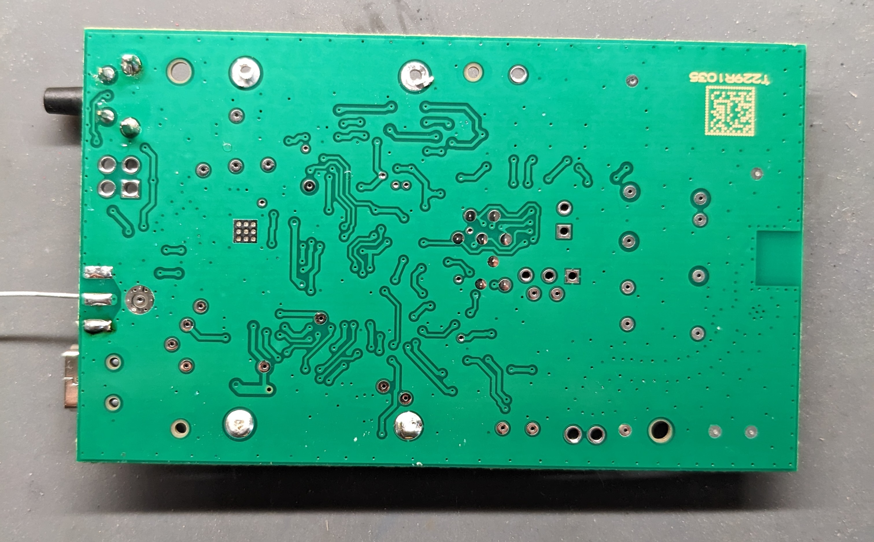
| 04:48, 24 April 2022 | Mainboard back pager.jpg (file) |  |
1.99 MB | 1 | |
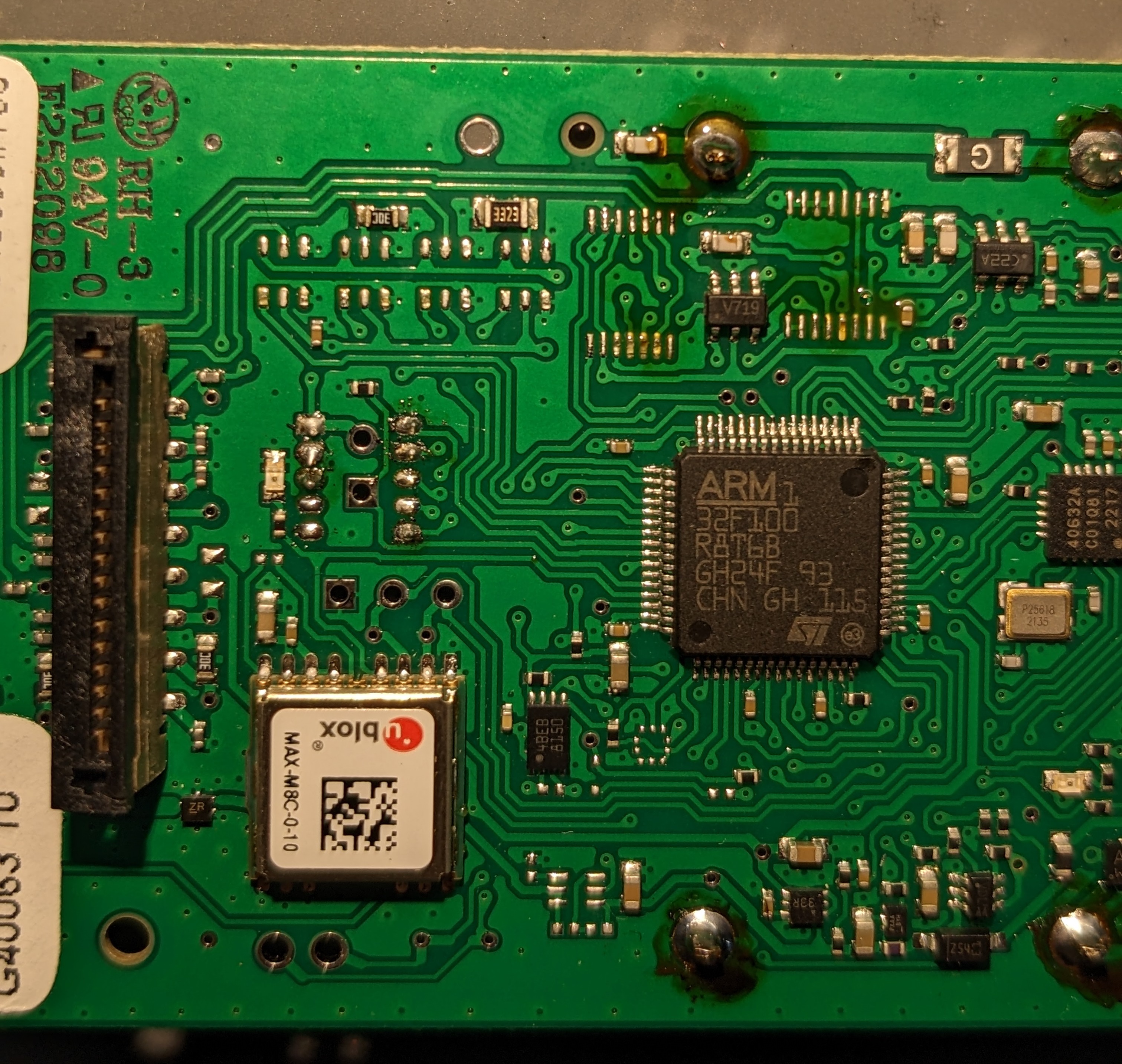
| 05:37, 16 January 2023 | V719 and others removed.jpg (file) |  |
1.99 MB | 1 | |
| 23:16, 15 April 2024 | Cdf bare mainboard.jpg (file) |  |
1.96 MB | Bare mainboard of the CD&F. All cards removed for visibility. | 1 |
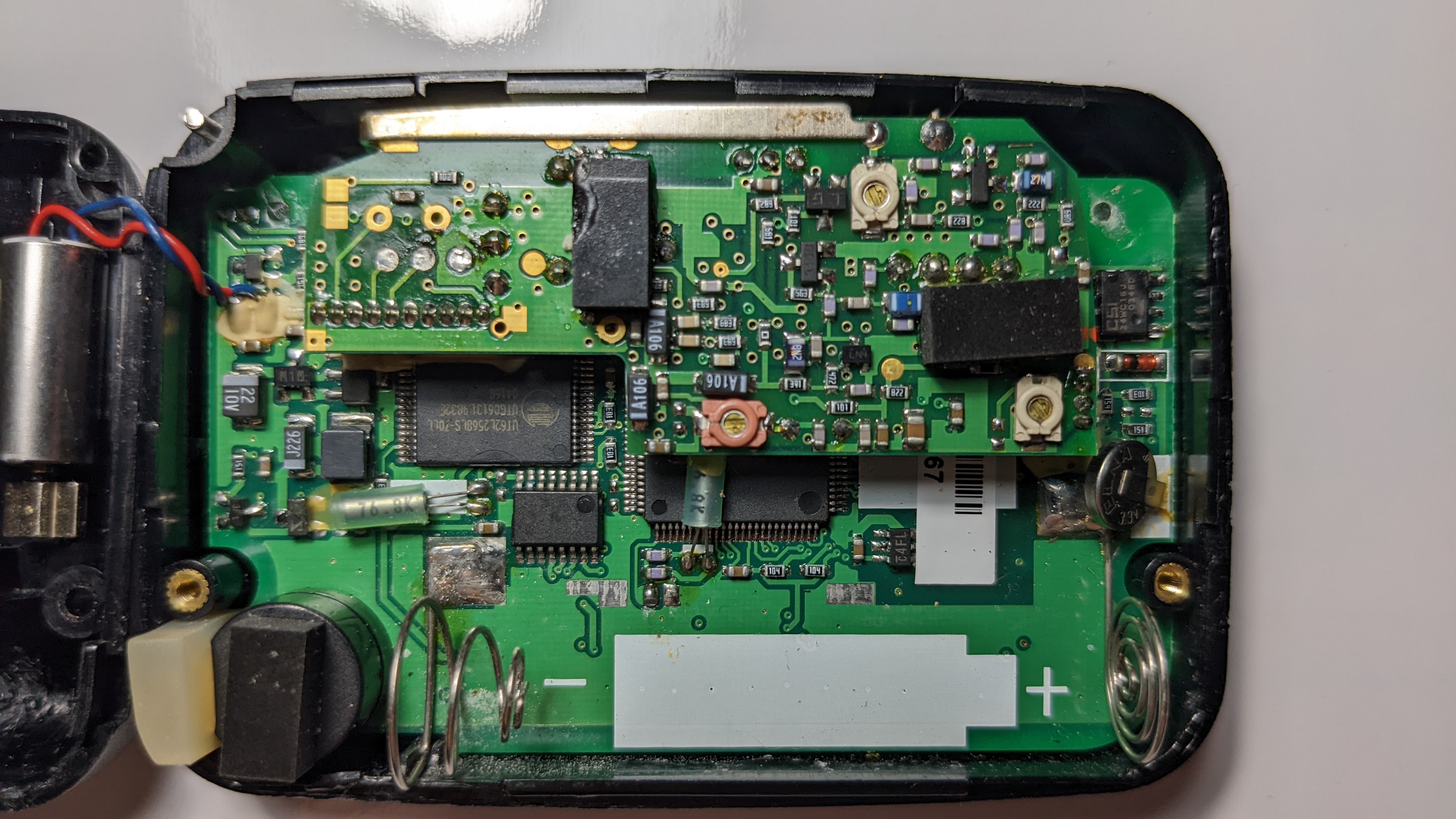
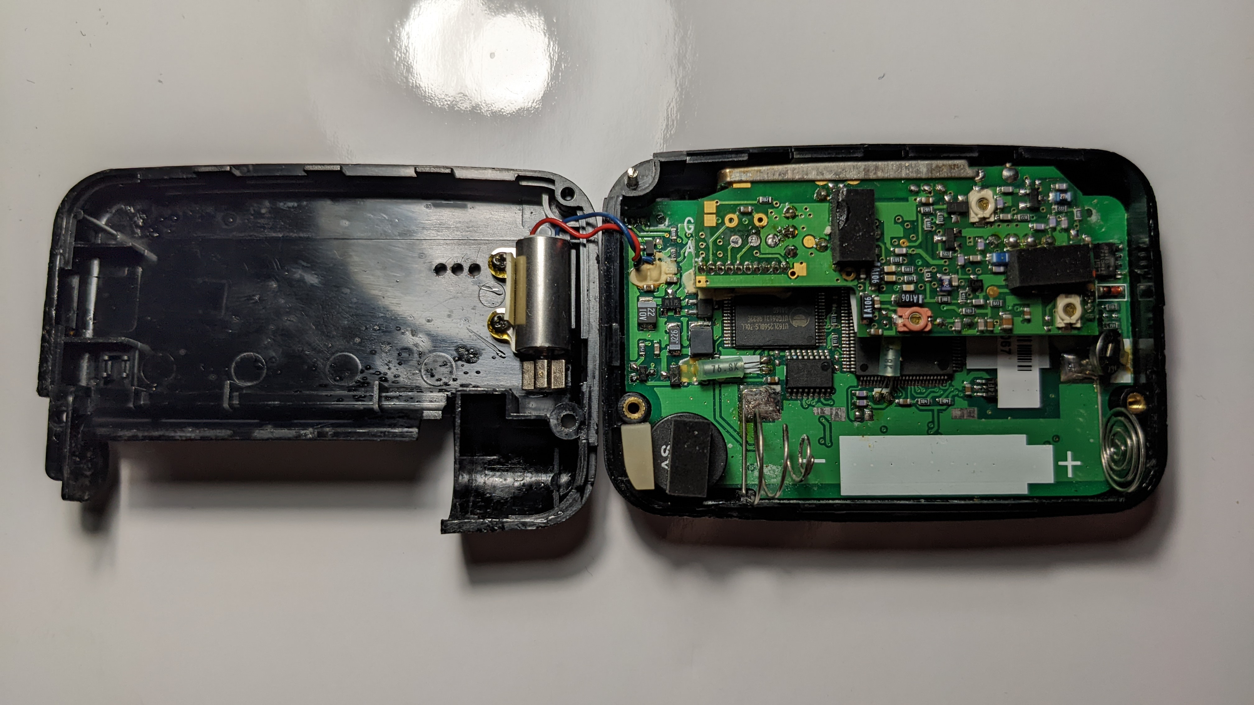
| 04:45, 24 April 2022 | Closeup circuitry pager.jpg (file) |  |
1.94 MB | 1 | |
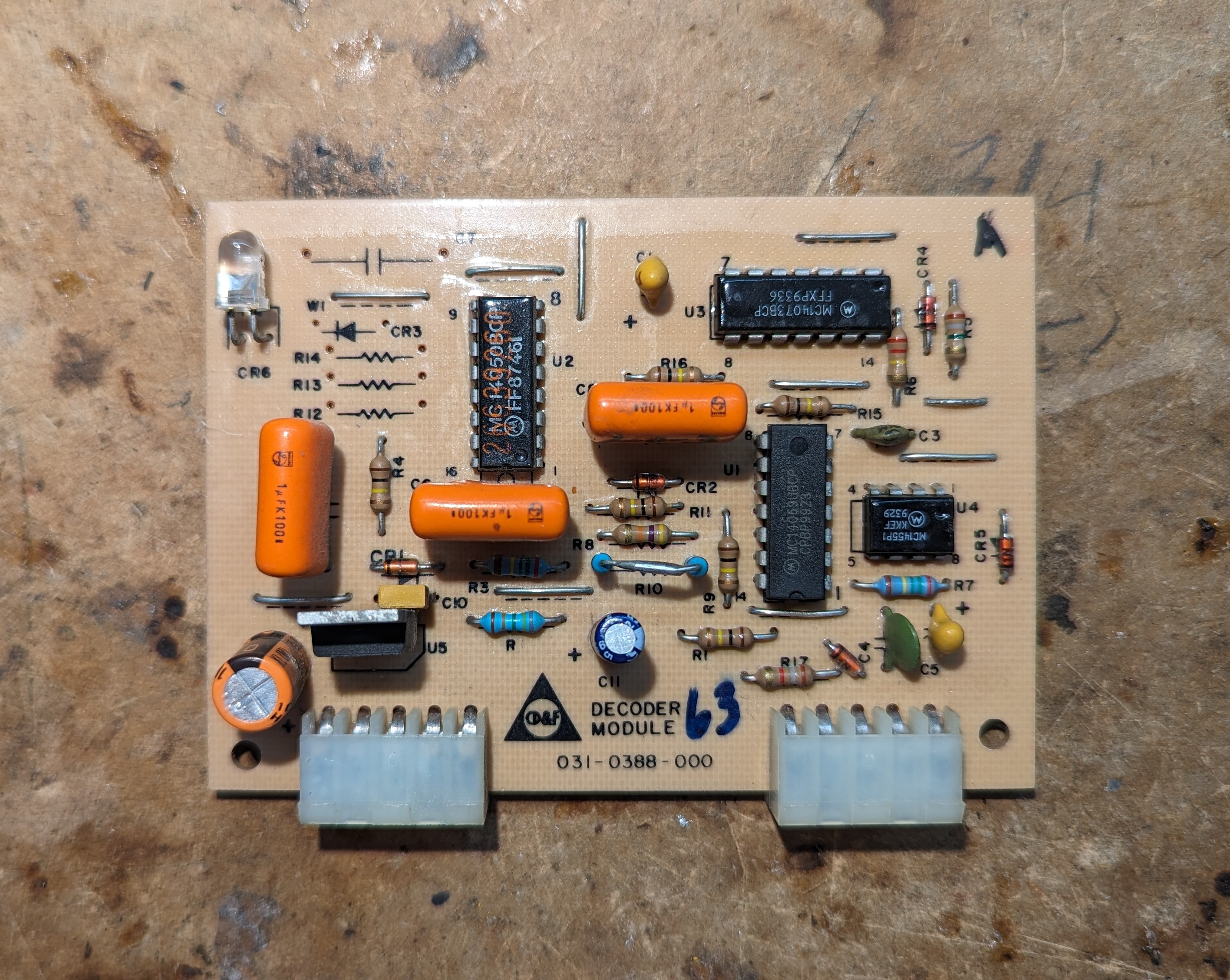
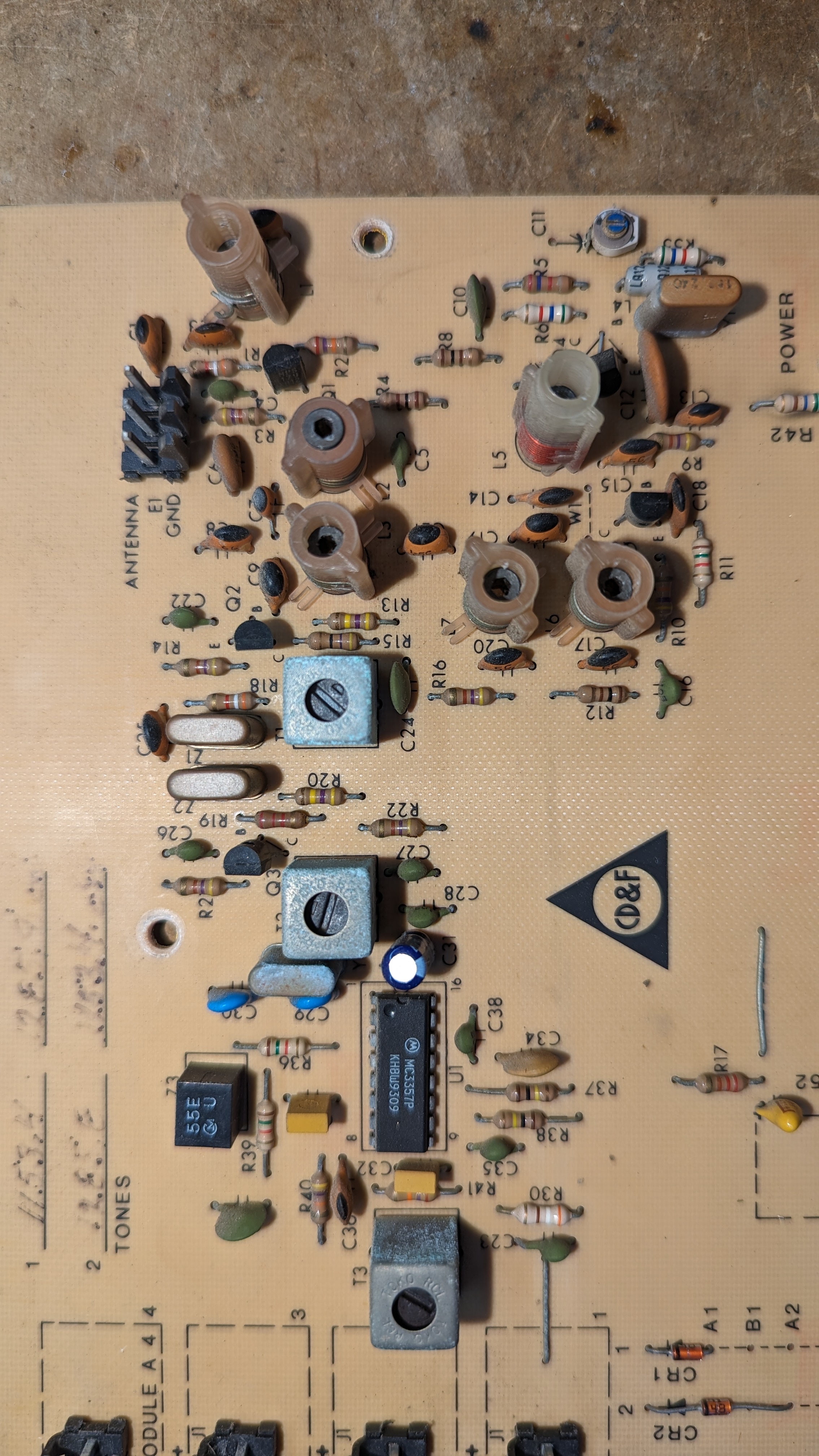
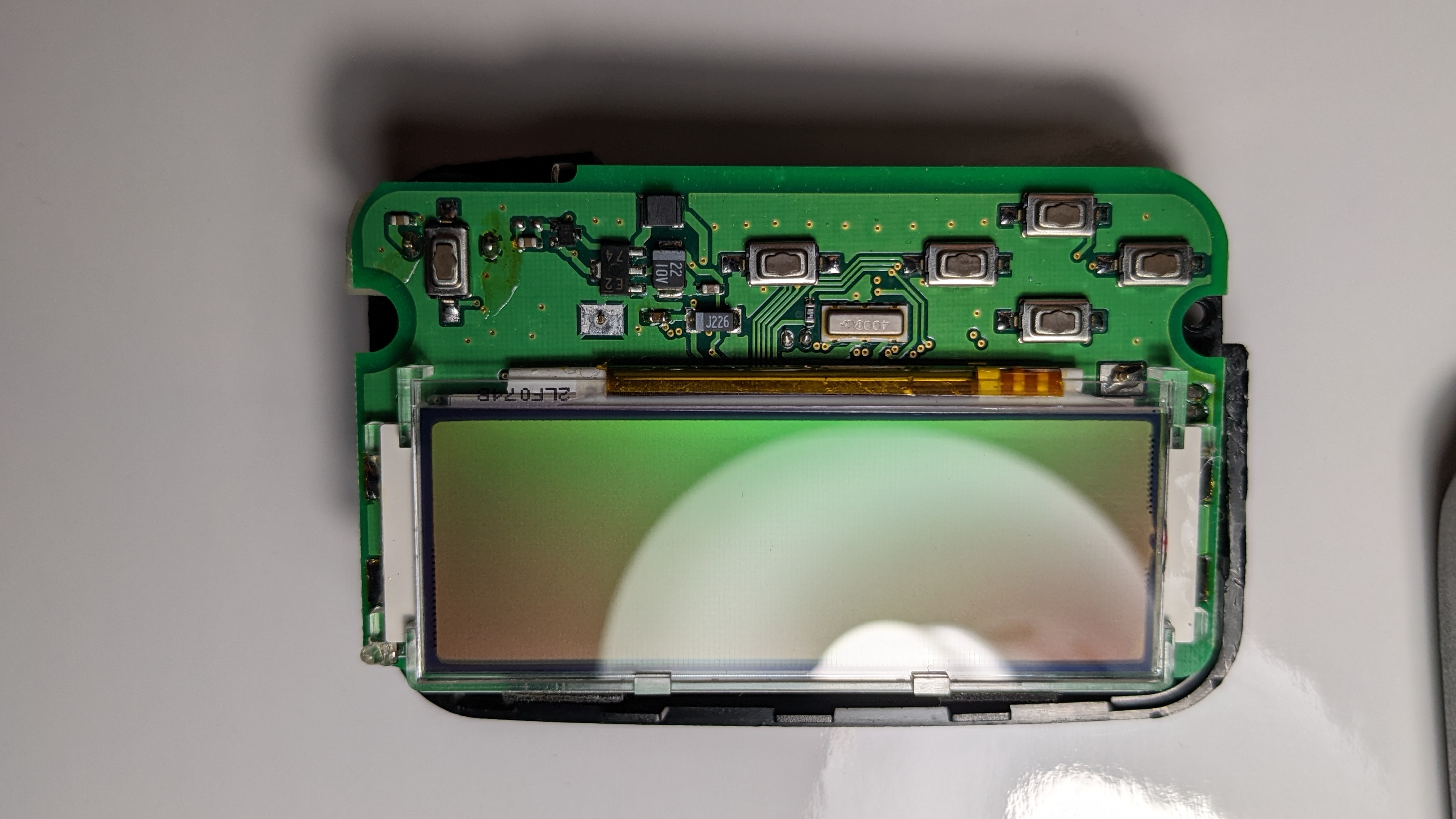
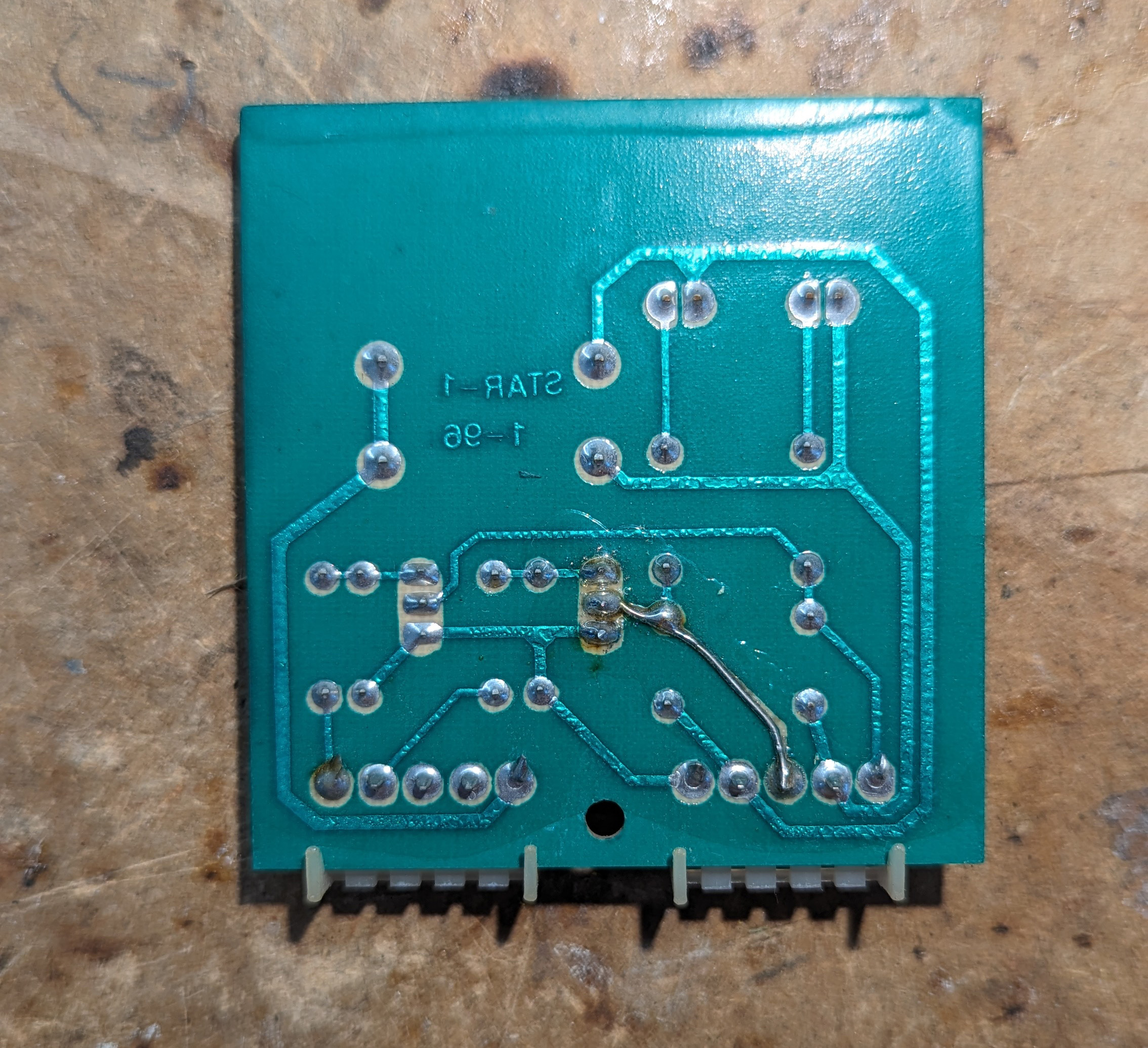
| 00:07, 17 April 2024 | Cdf decoder module a front.jpg (file) |  |
1.94 MB | Front of the tone decoder module from the CD&F | 1 |
| 23:22, 15 April 2024 | Cdf rx closeup.jpg (file) |  |
1.94 MB | Closeup of the double conversion super heterodyne radio receiver circuitry in the CD&F | 1 |
| 00:10, 17 April 2024 | Cdf cycle timer back.jpg (file) |  |
1.91 MB | Cycle timer (Steady) backside (Mirrored to match Cdf_cycle_timer_front.jpg) | 1 |
| 00:36, 9 August 2022 | Sticky pads.jpg (file) |  |
1.85 MB | 1 | |
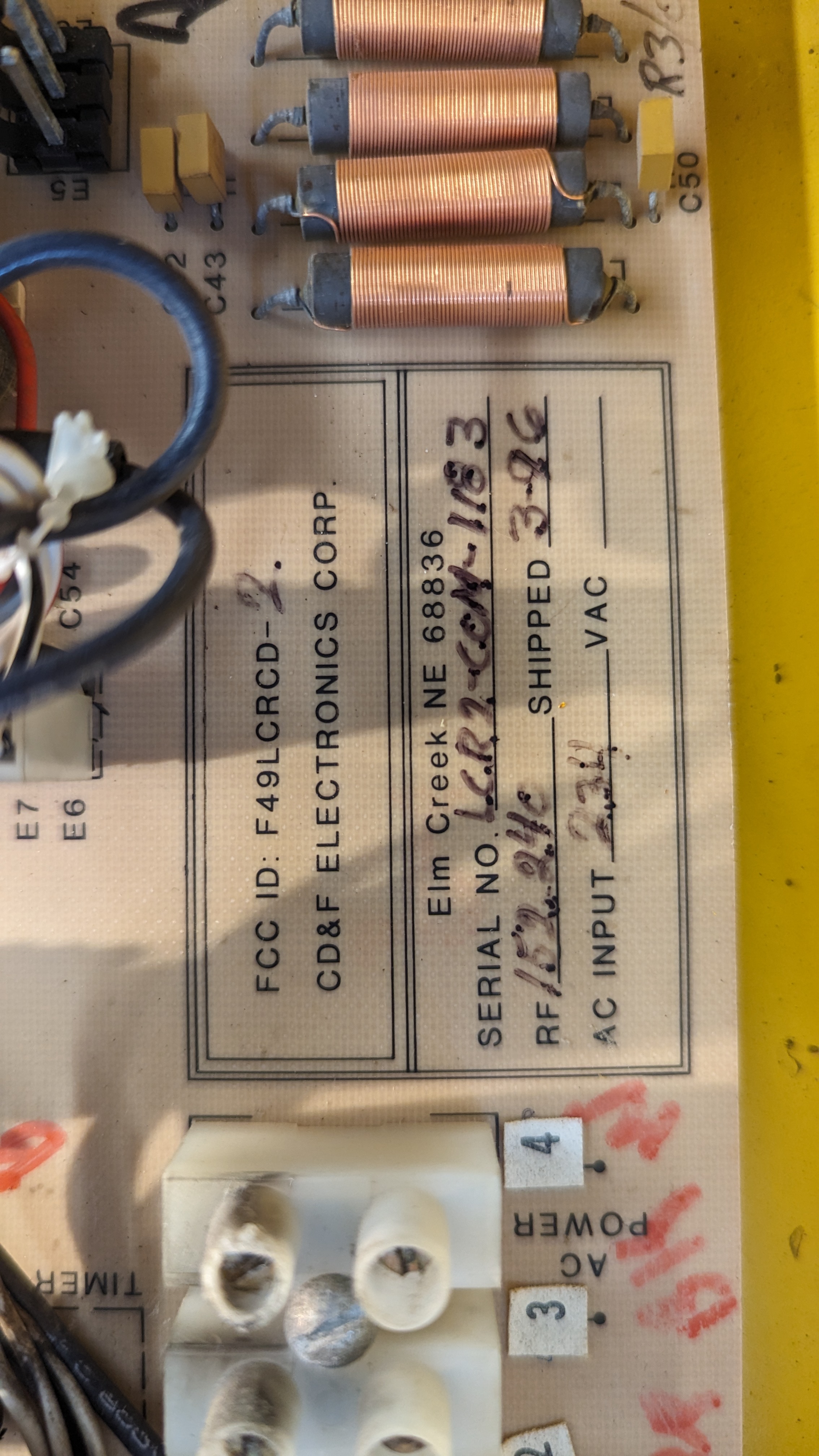
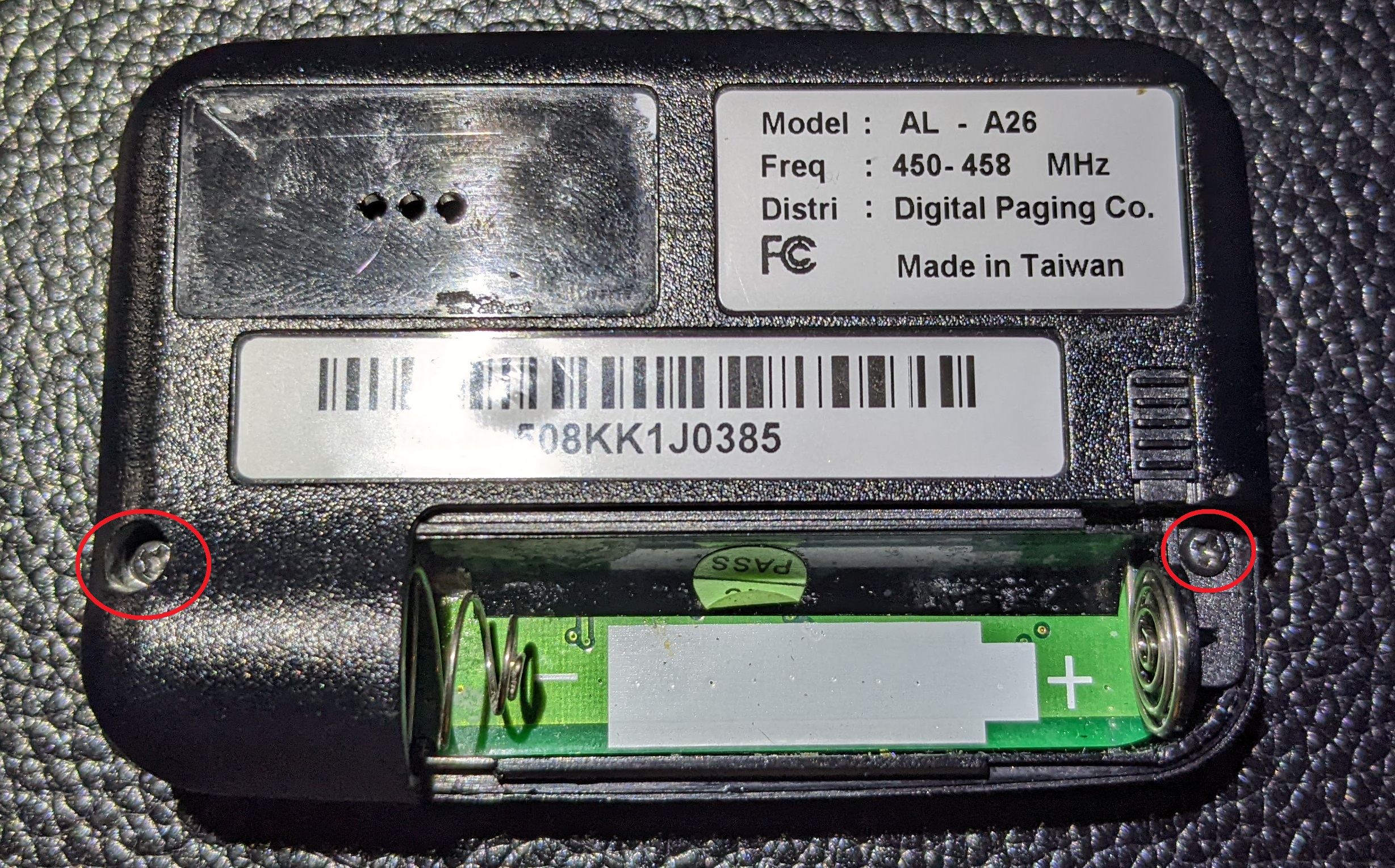
| 23:13, 15 April 2024 | Cdf info onboard.jpg (file) |  |
1.79 MB | Info written near the bottom center of the mainboard. Shows FCC-ID, serial, receive frequency, input voltage, and ship date. | 1 |
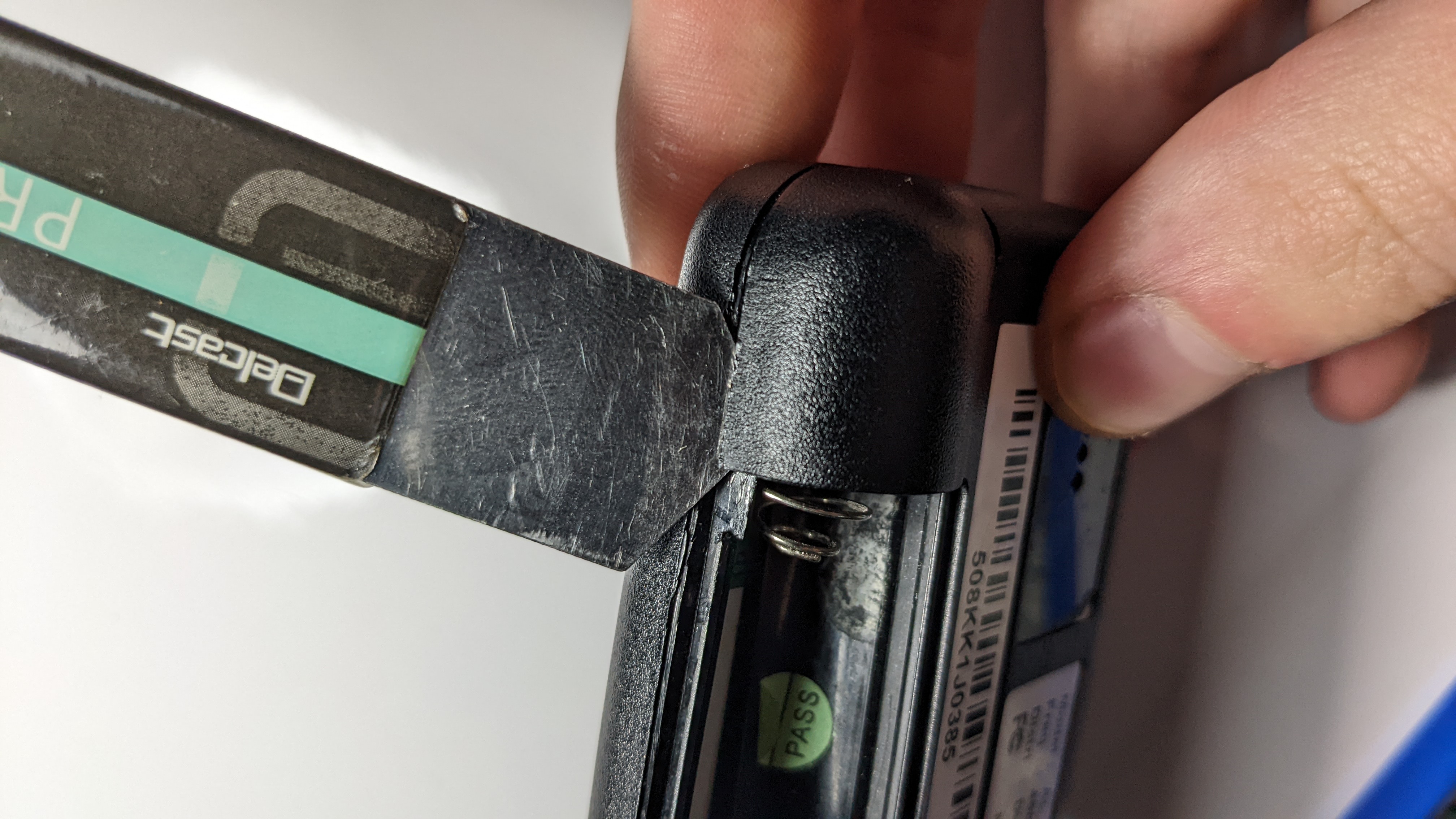
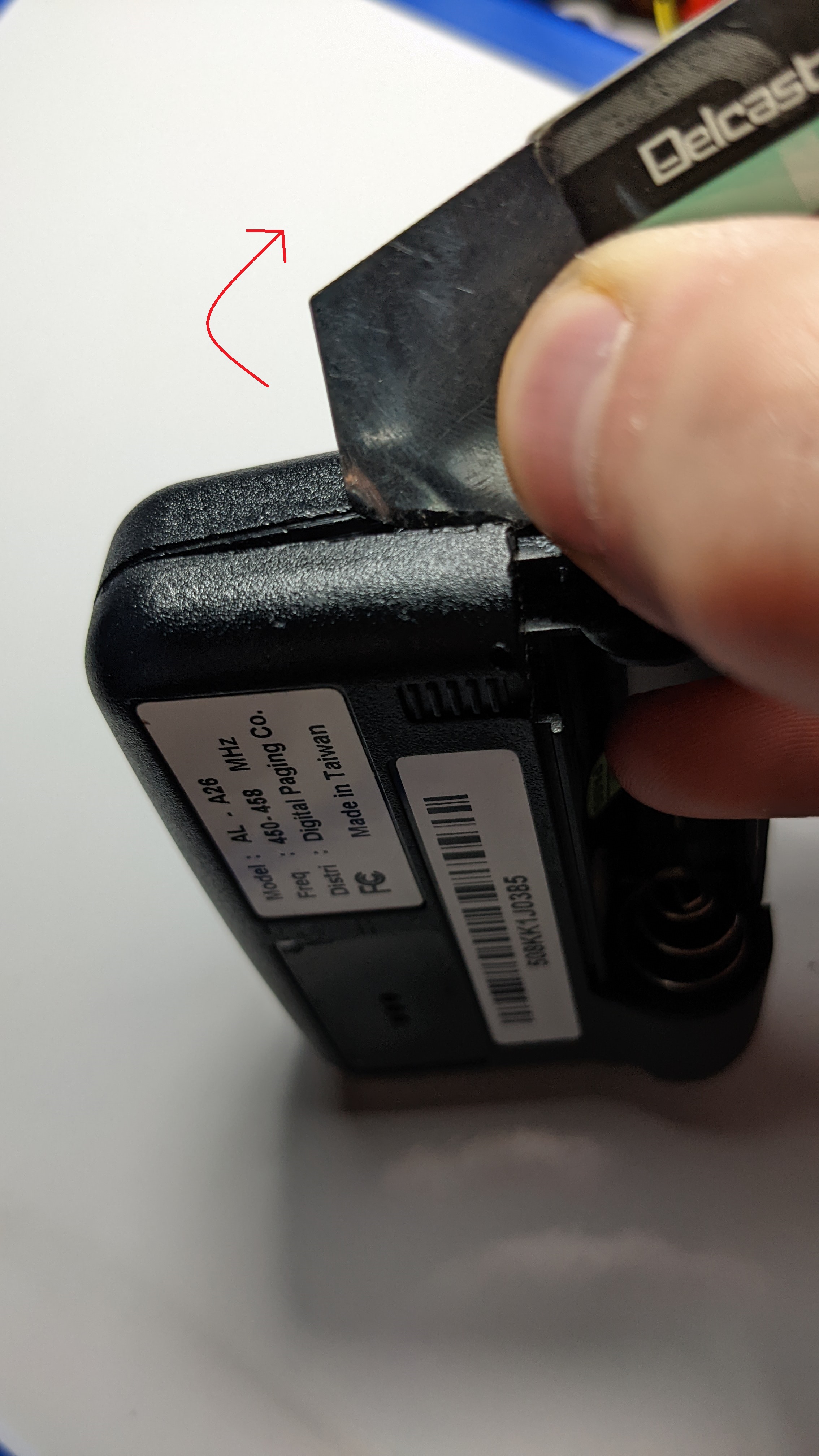
| 04:48, 24 April 2022 | Left side spudger insert pager.jpg (file) |  |
1.79 MB | 1 | |
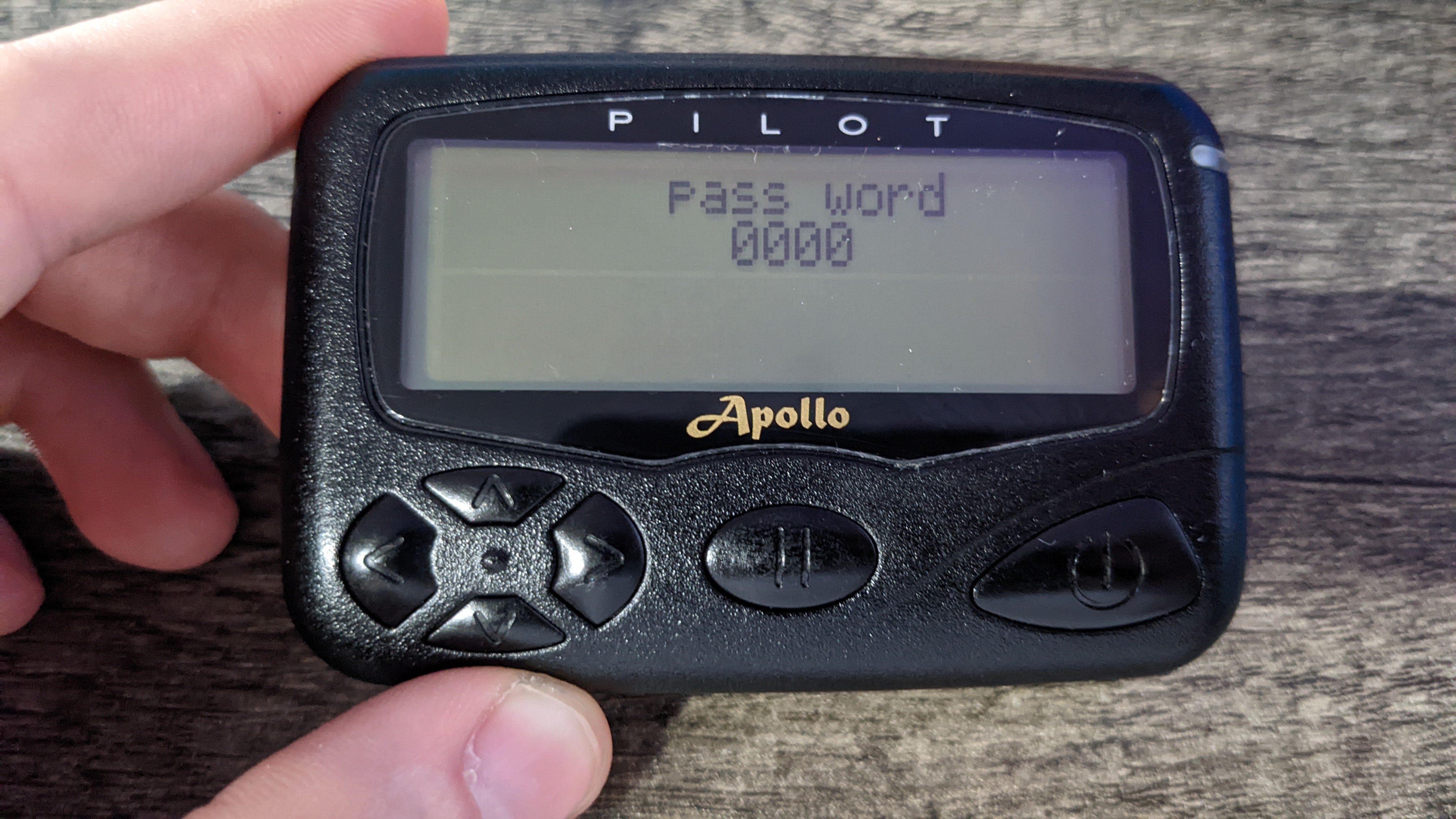
| 00:35, 9 August 2022 | Pass word prompt.jpg (file) |  |
1.77 MB | 1 | |
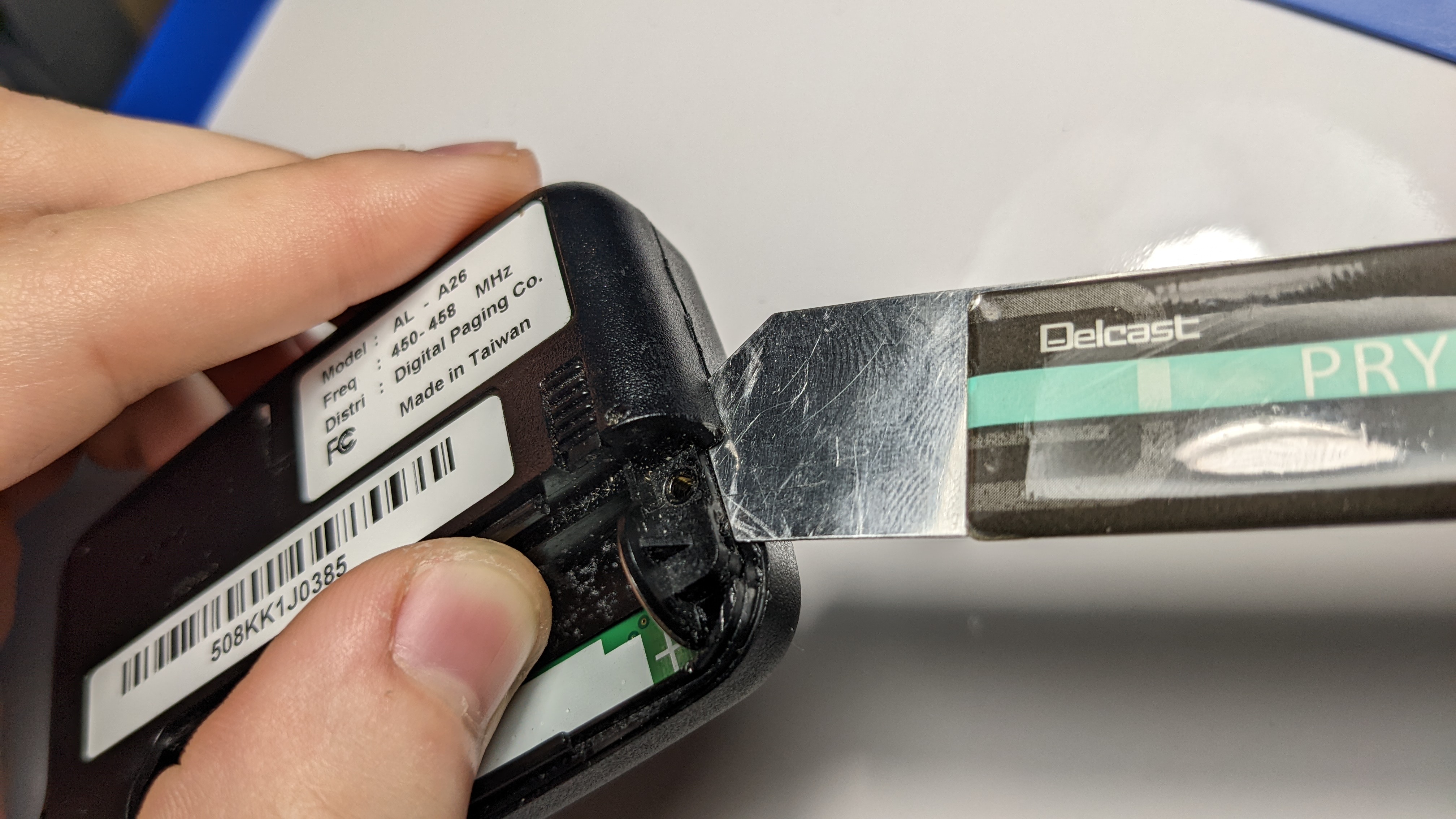
| 04:48, 24 April 2022 | Insert spudger right side pager.jpg (file) |  |
1.71 MB | 1 | |
| 00:34, 9 August 2022 | Contrast menu.jpg (file) |  |
1.71 MB | 1 | |
| 04:45, 24 April 2022 | Completely free back pager.jpg (file) |  |
1.71 MB | 1 | |
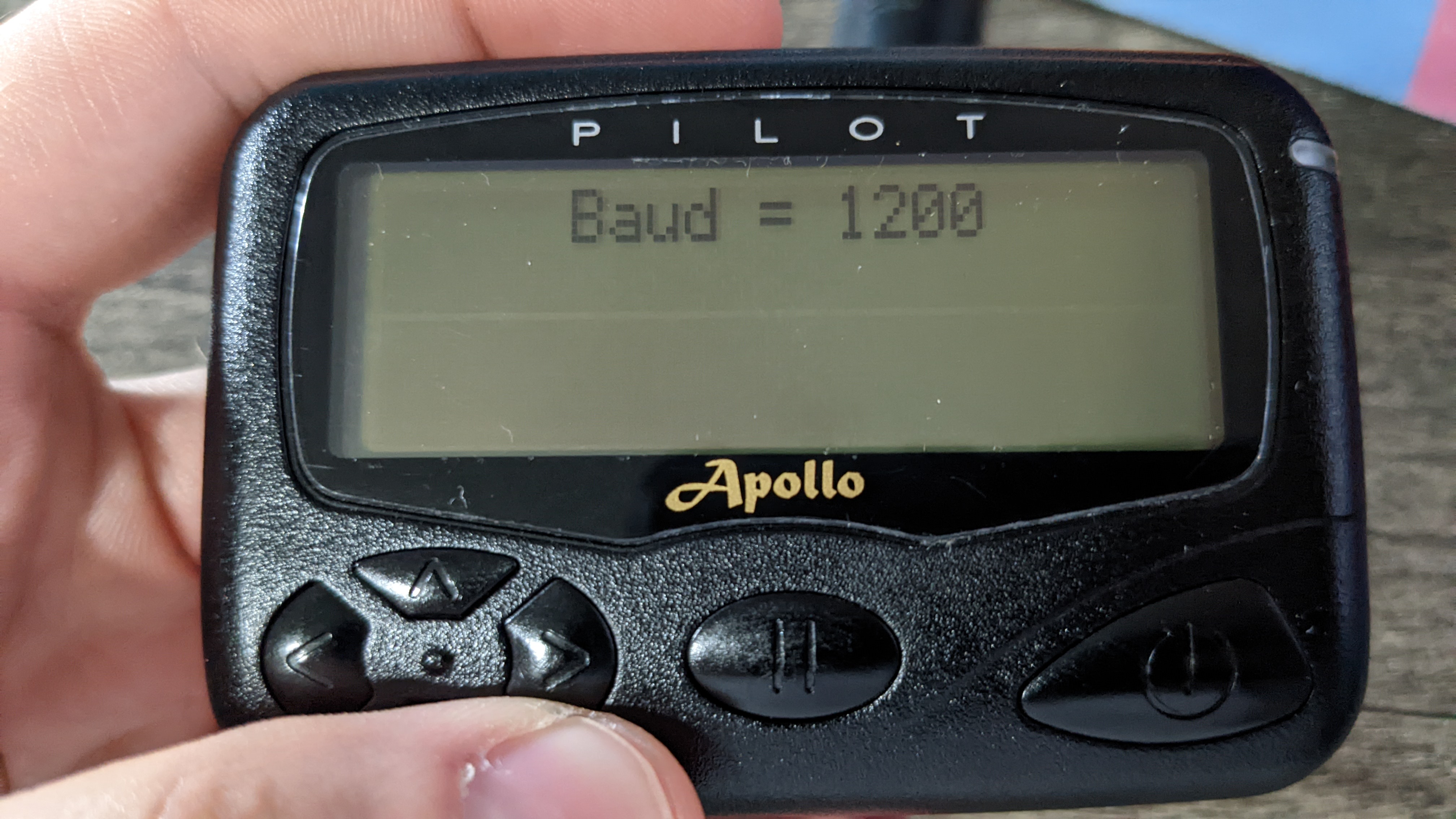
| 00:33, 9 August 2022 | Baud menu.jpg (file) |  |
1.7 MB | 2 | |
| 04:44, 24 April 2022 | Back laid flat pager.jpg (file) |  |
1.7 MB | 1 | |
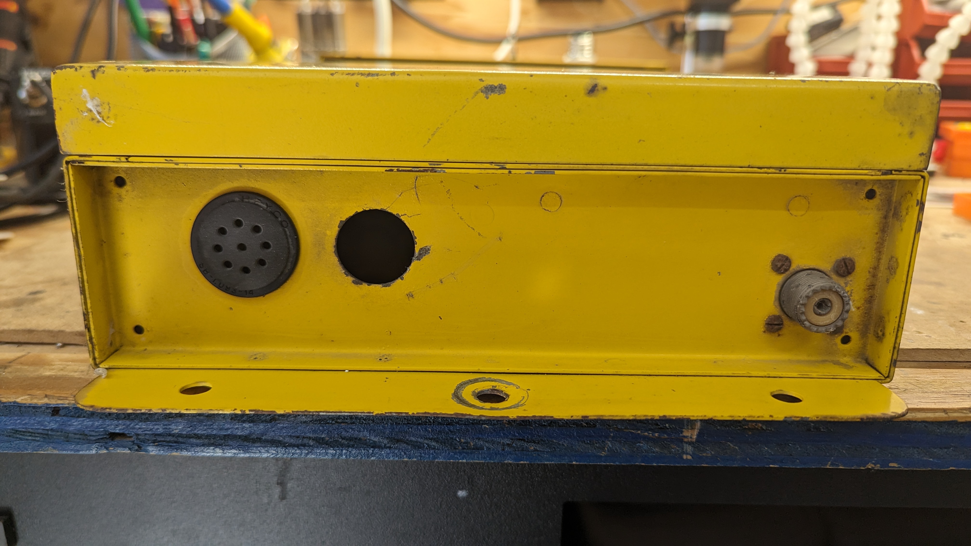
| 23:07, 15 April 2024 | Cdf bottom.jpg (file) |  |
1.68 MB | Bottom of the CD&F housing showing the conduit and vent holes as well as an unused SO-239 connector for replacing the whip antenna. | 1 |
| 04:50, 24 April 2022 | Screw locations pager.jpg (file) |  |
1.67 MB | 1 | |
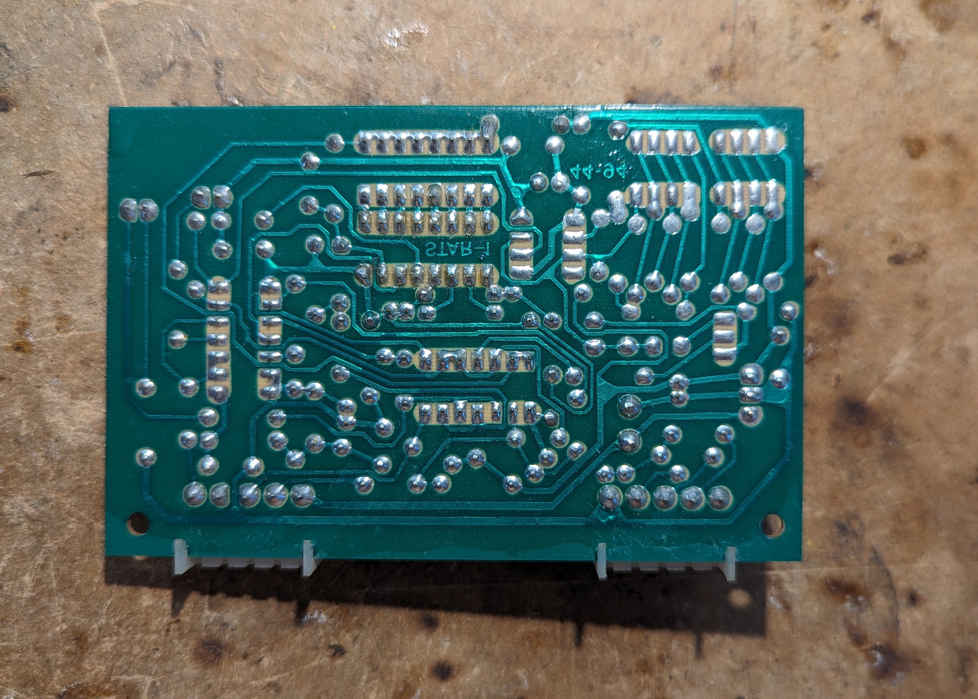
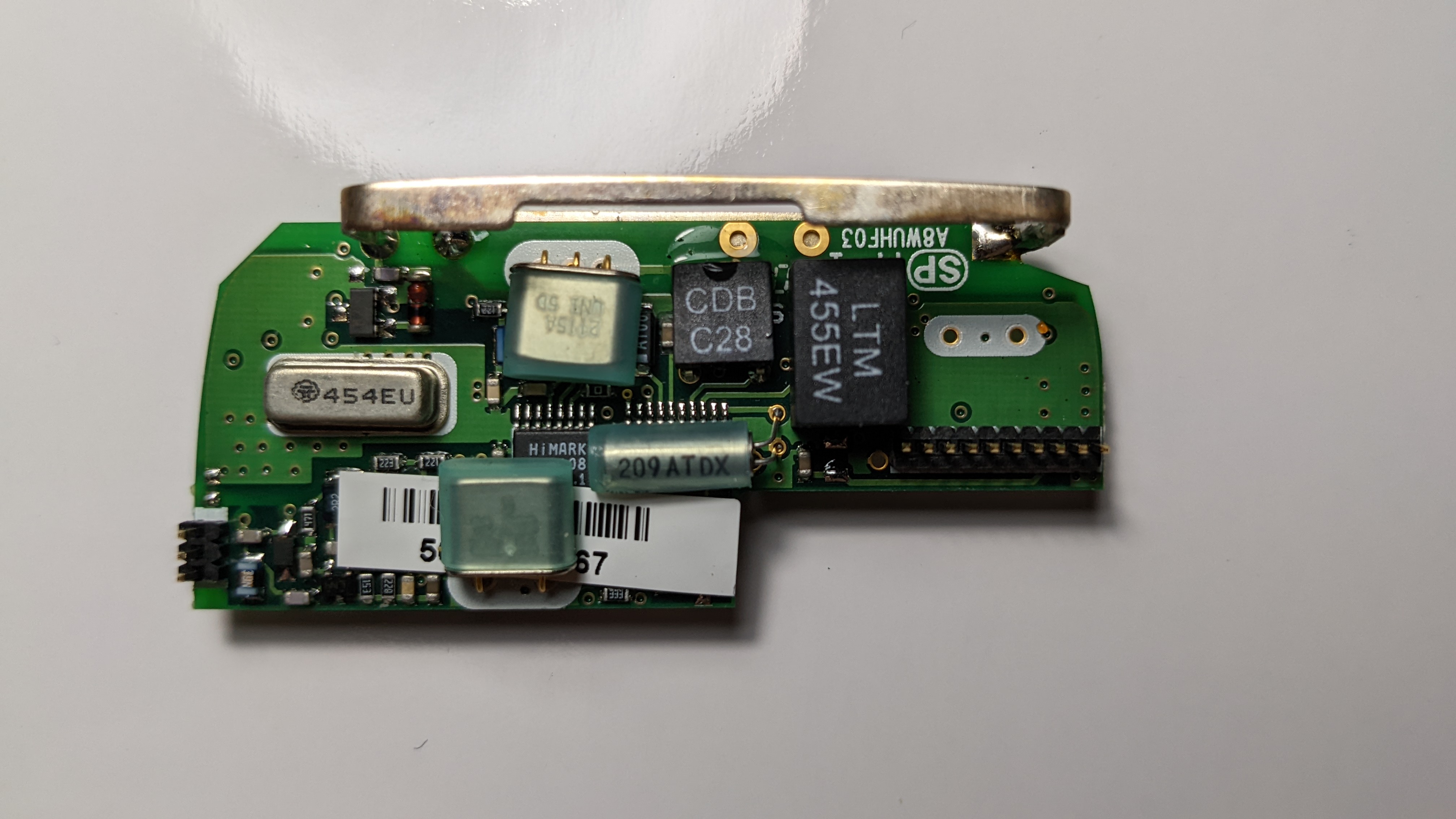
| 00:09, 17 April 2024 | Cdf decoder module a back.jpg (file) |  |
1.67 MB | Backside of the tone decoder module from the CD&F (Mirrored to match Cdf_decoder_module_a_front.jpg | 1 |
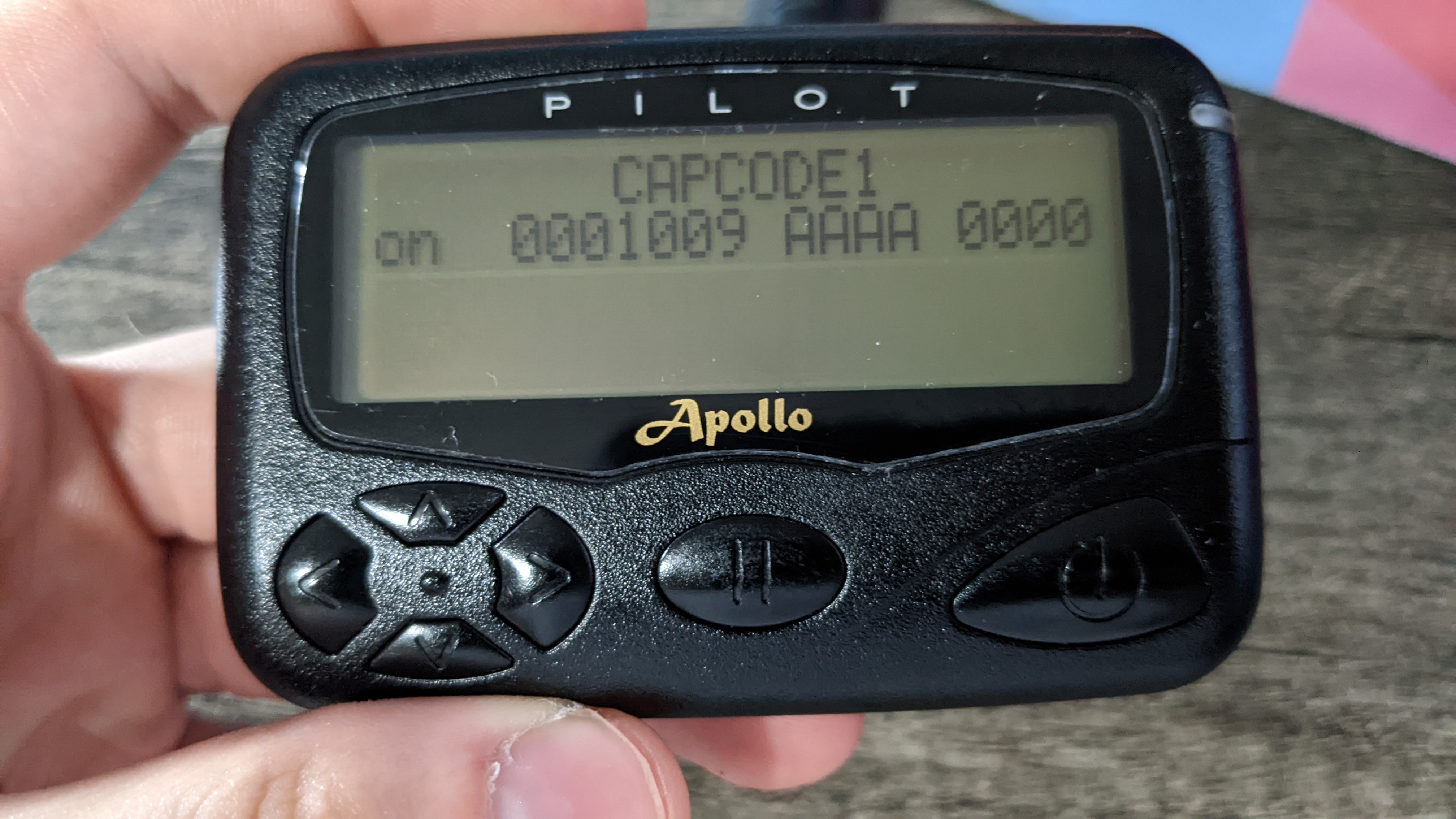
| 00:34, 9 August 2022 | Capcode menu.jpg (file) |  |
1.66 MB | 1 | |
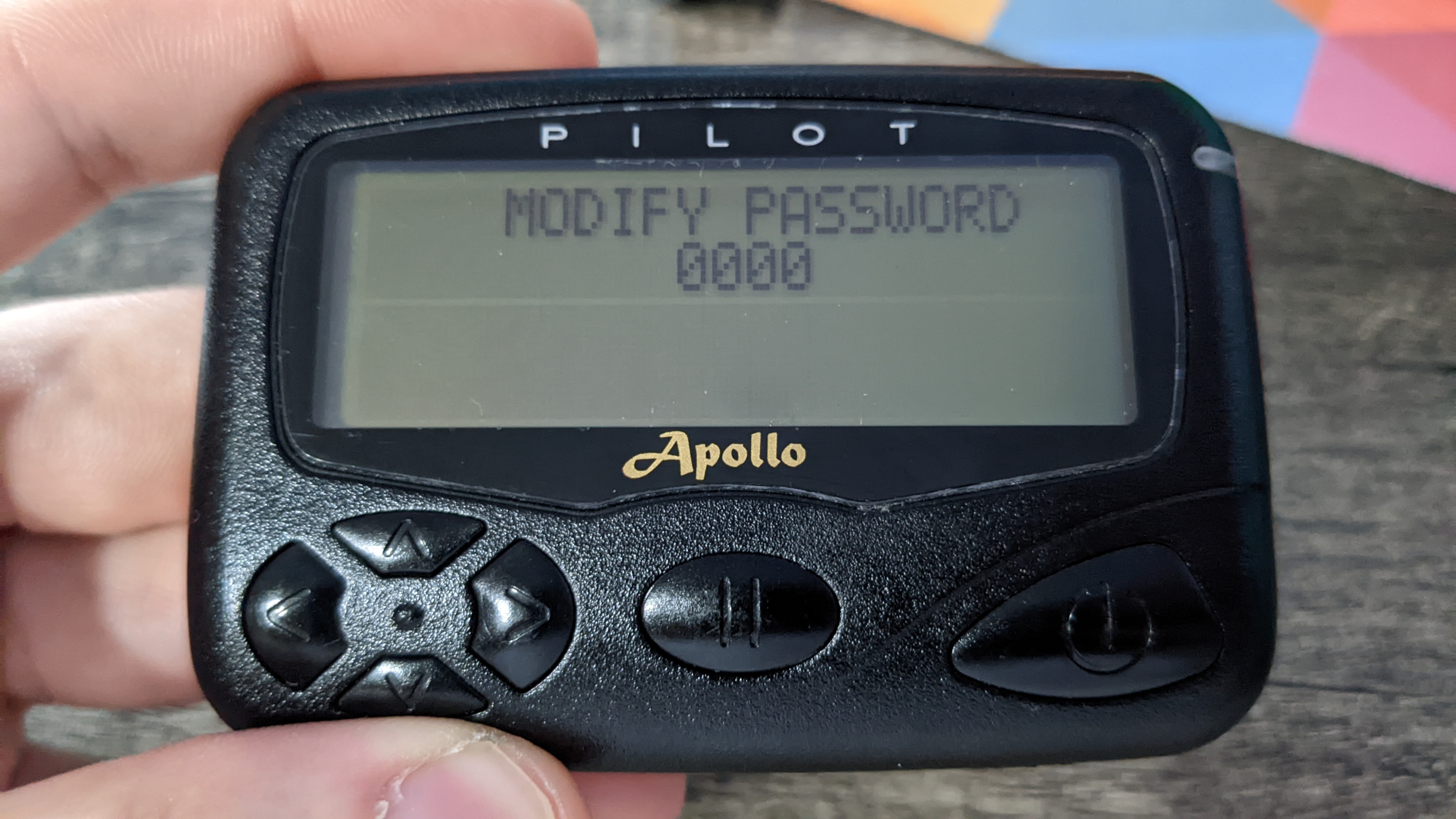
| 00:35, 9 August 2022 | Modify password menu.jpg (file) |  |
1.66 MB | 1 | |
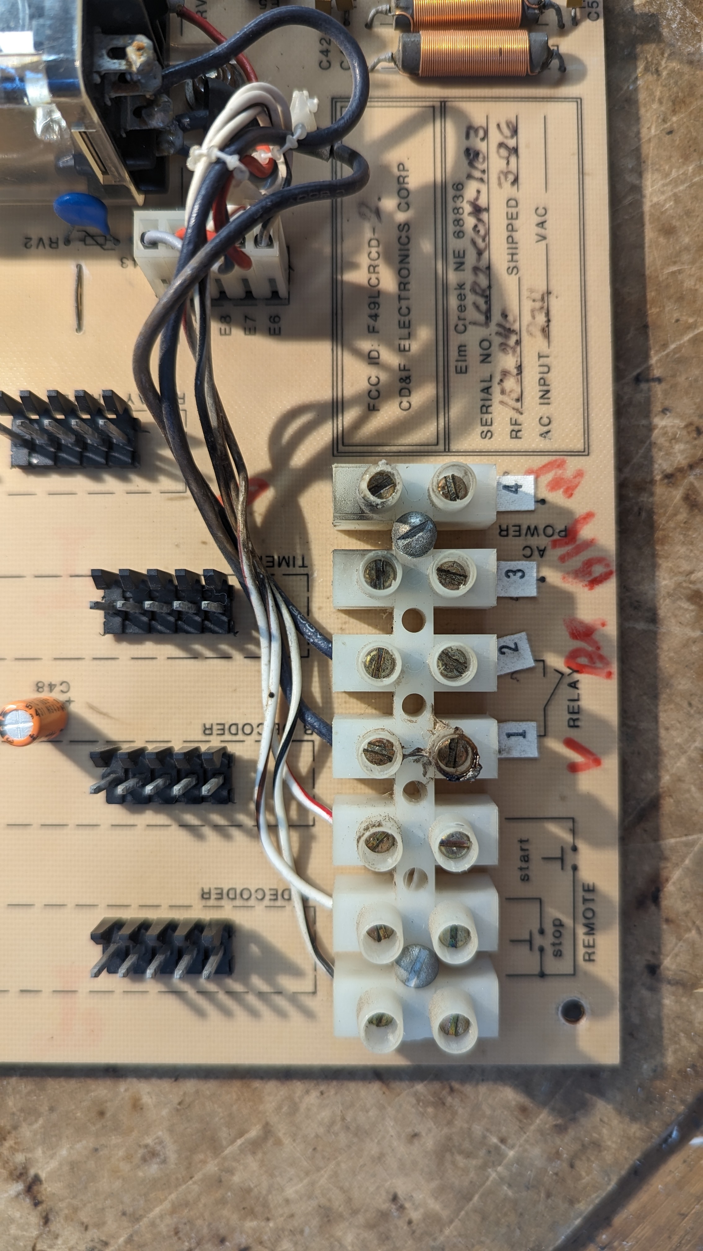
| 06:05, 15 April 2024 | Cdf terminals closeup.jpg (file) |  |
1.62 MB | Closeup of the terminal block on the CD&F controller | 1 |
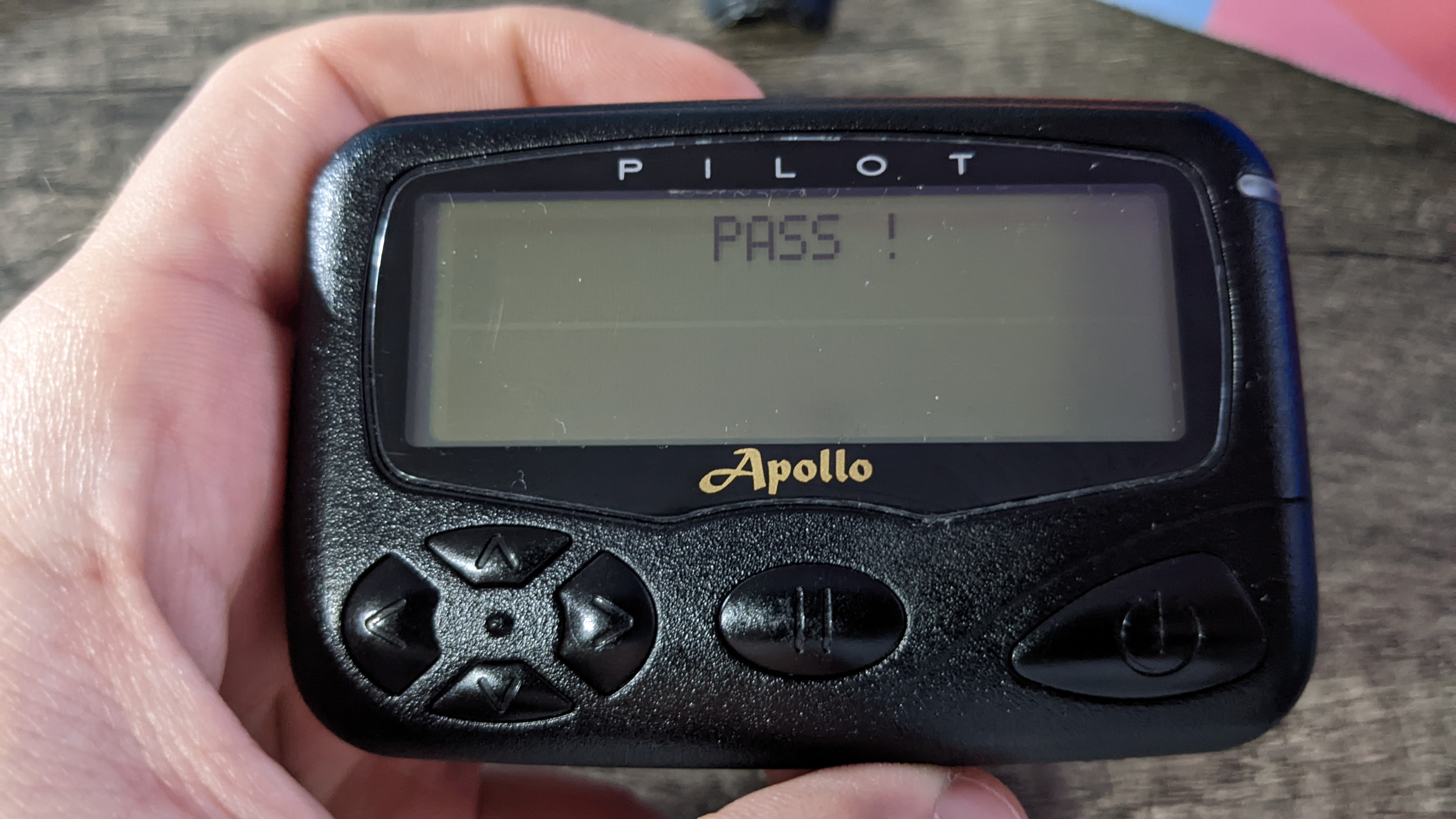
| 00:35, 9 August 2022 | Pass screen.jpg (file) |  |
1.55 MB | 1 | |
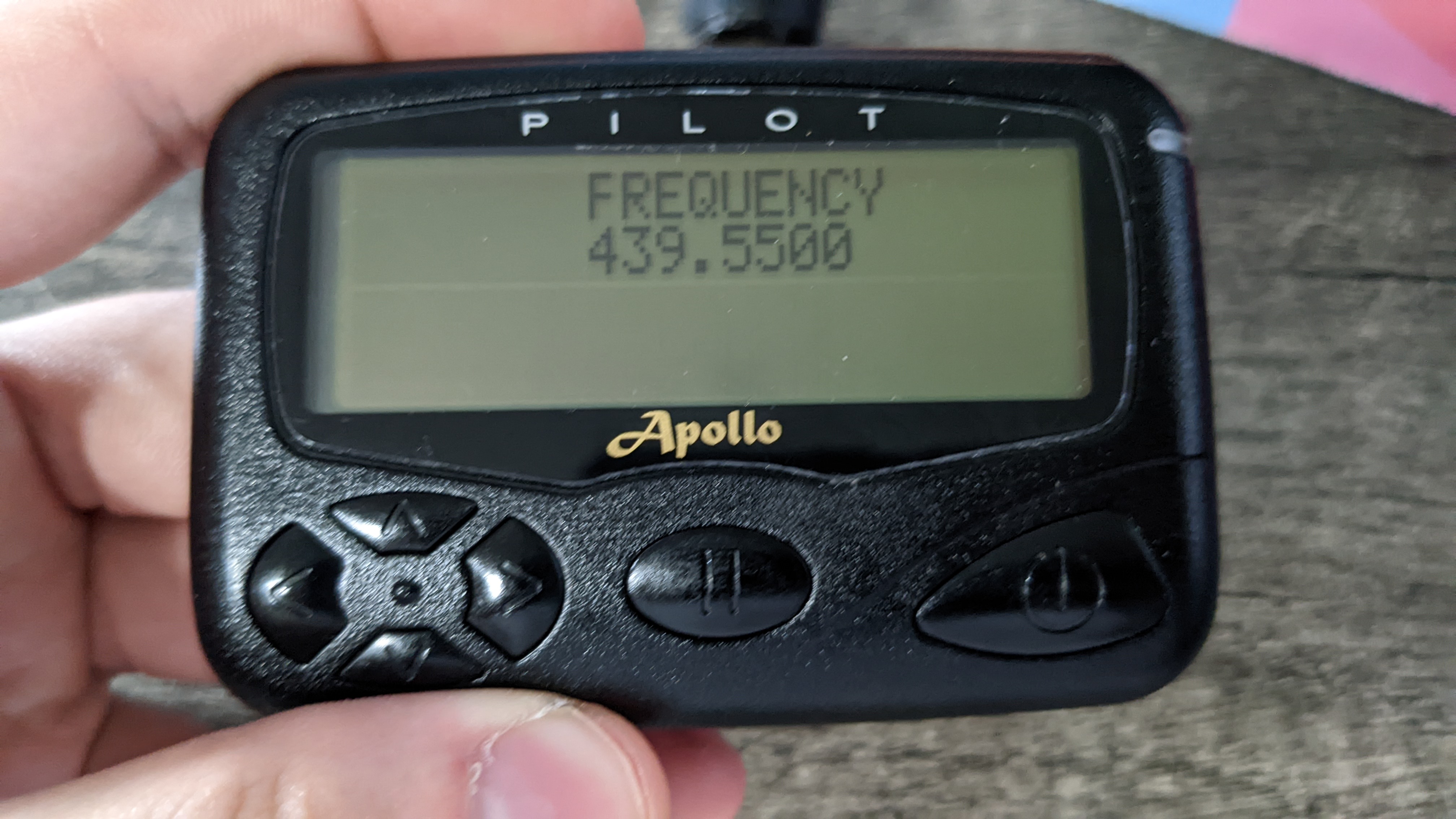
| 00:35, 9 August 2022 | Frequency menu.jpg (file) |  |
1.53 MB | 1 | |
| 04:49, 24 April 2022 | RF board back pager.jpg (file) |  |
1.5 MB | 1 | |
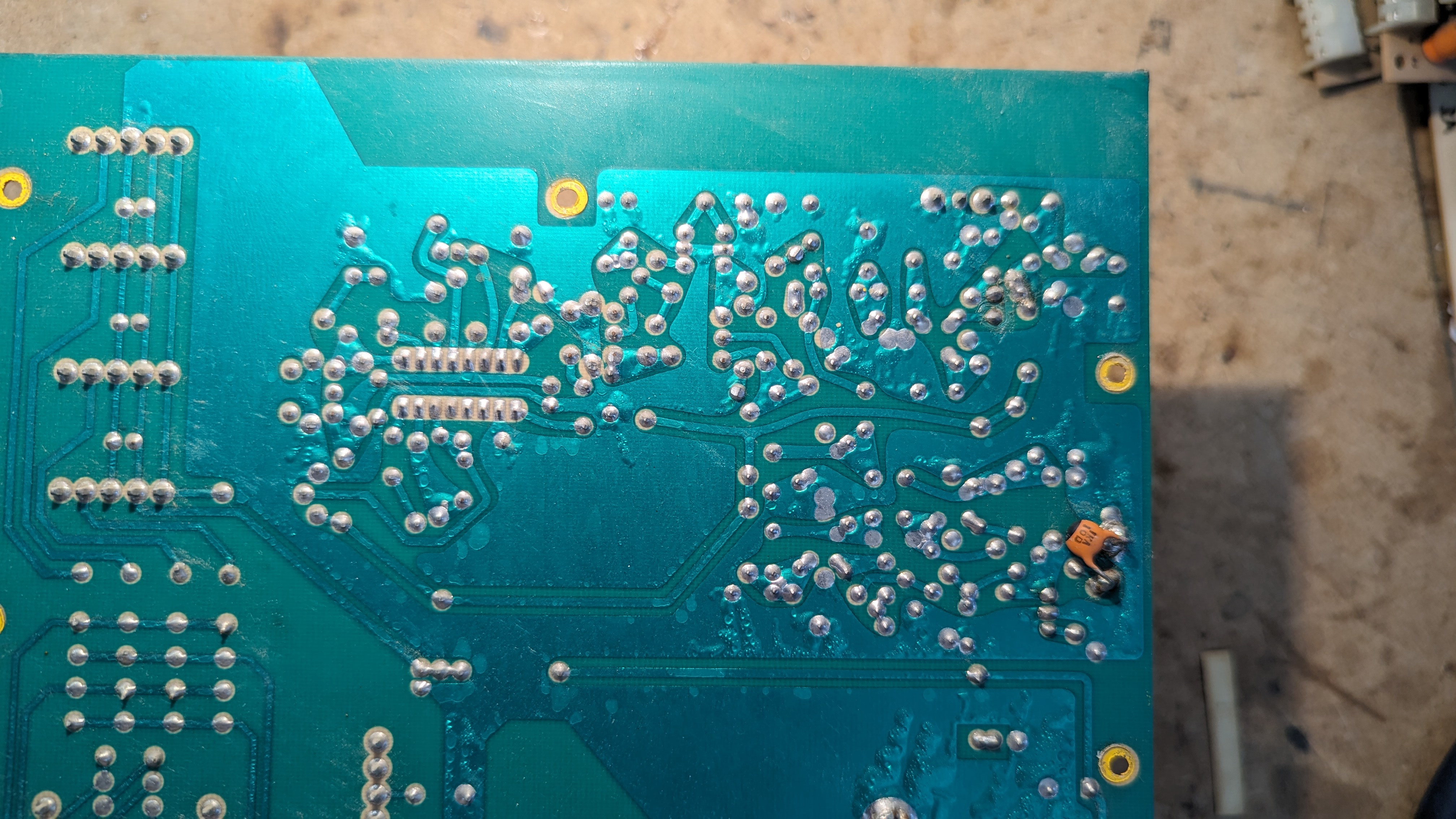
| 23:21, 15 April 2024 | Cdf bare mainboard back.jpg (file) |  |
1.48 MB | Flipped horizontally to match Cdf_bare_mainboard.jpg | 2 |
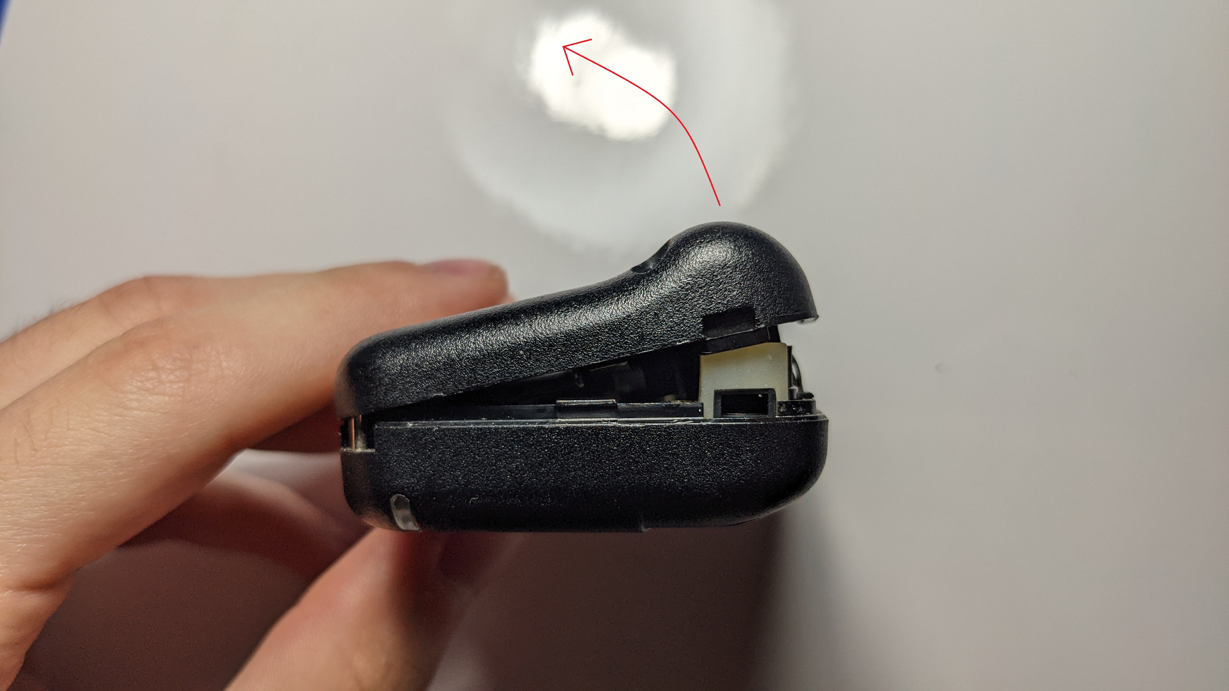
| 04:49, 24 April 2022 | Not fully snapped left pager.jpg (file) |  |
1.46 MB | 1 | |
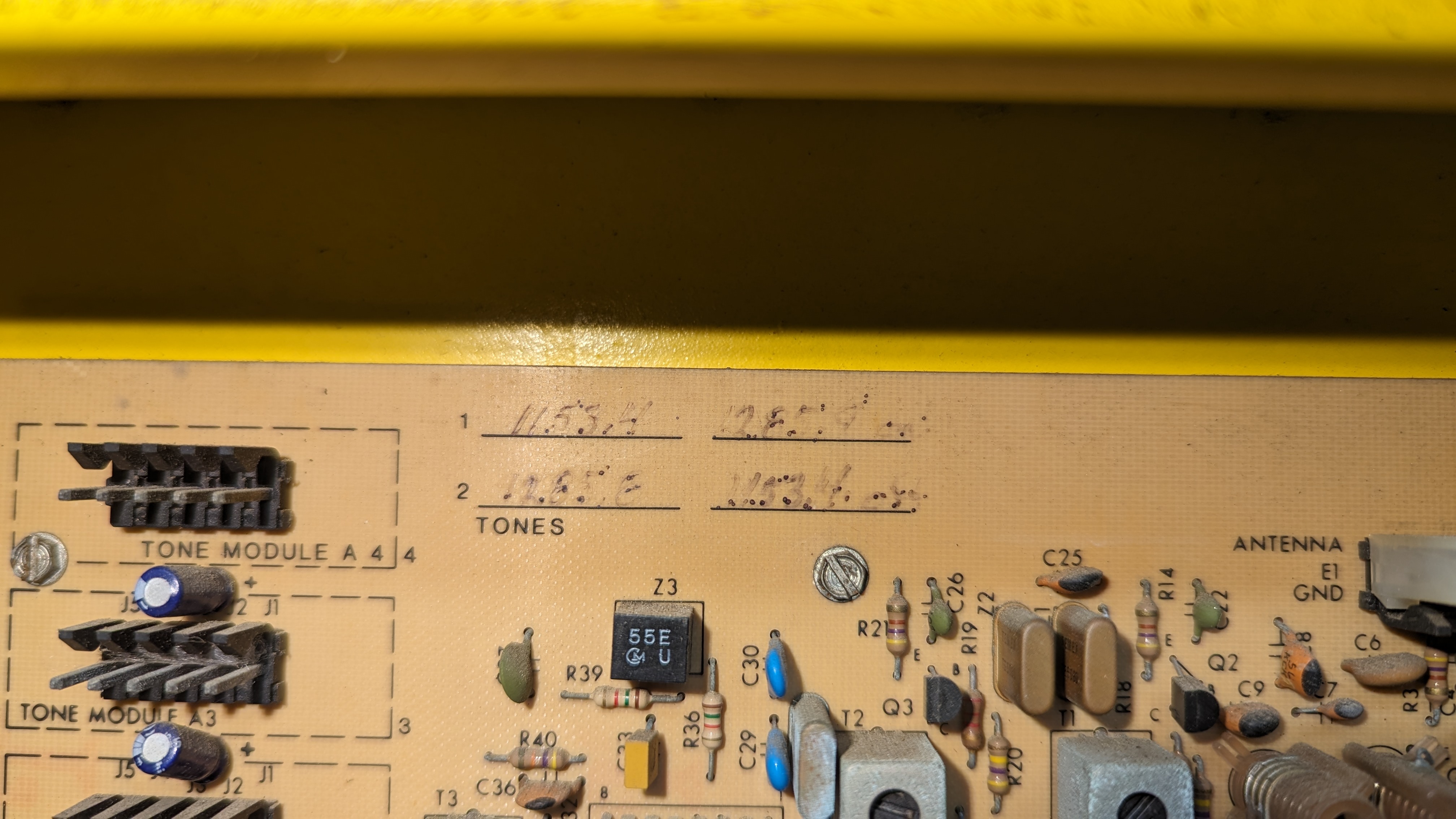
| 23:26, 15 April 2024 | Cdf tone info.jpg (file) |  |
1.46 MB | Configured tone information handwritten on the CD&F main board near the top center. Sequence 1 is to activate, sequence 2 is to deactivate. | 1 |
| 04:49, 24 April 2022 | Mainboard front pager.jpg (file) |  |
1.45 MB | 1 | |
| 04:50, 24 April 2022 | Top edge flush reassembly pager.jpg (file) |  |
1.43 MB | 1 | |
| 04:50, 24 April 2022 | RF board front pager.jpg (file) |  |
1.34 MB | 1 | |
| 04:50, 24 April 2022 | Right side unsnapped pager.jpg (file) |  |
1.33 MB | 1 | |
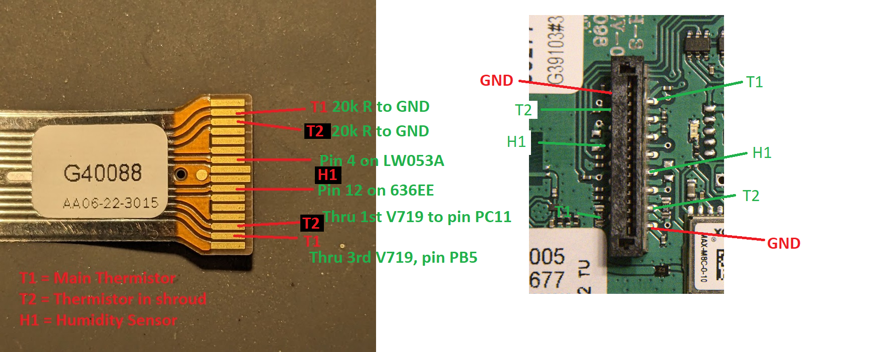
| 05:39, 16 January 2023 | Stalk pinout mapping.png (file) |  |
1.33 MB | 1 | |
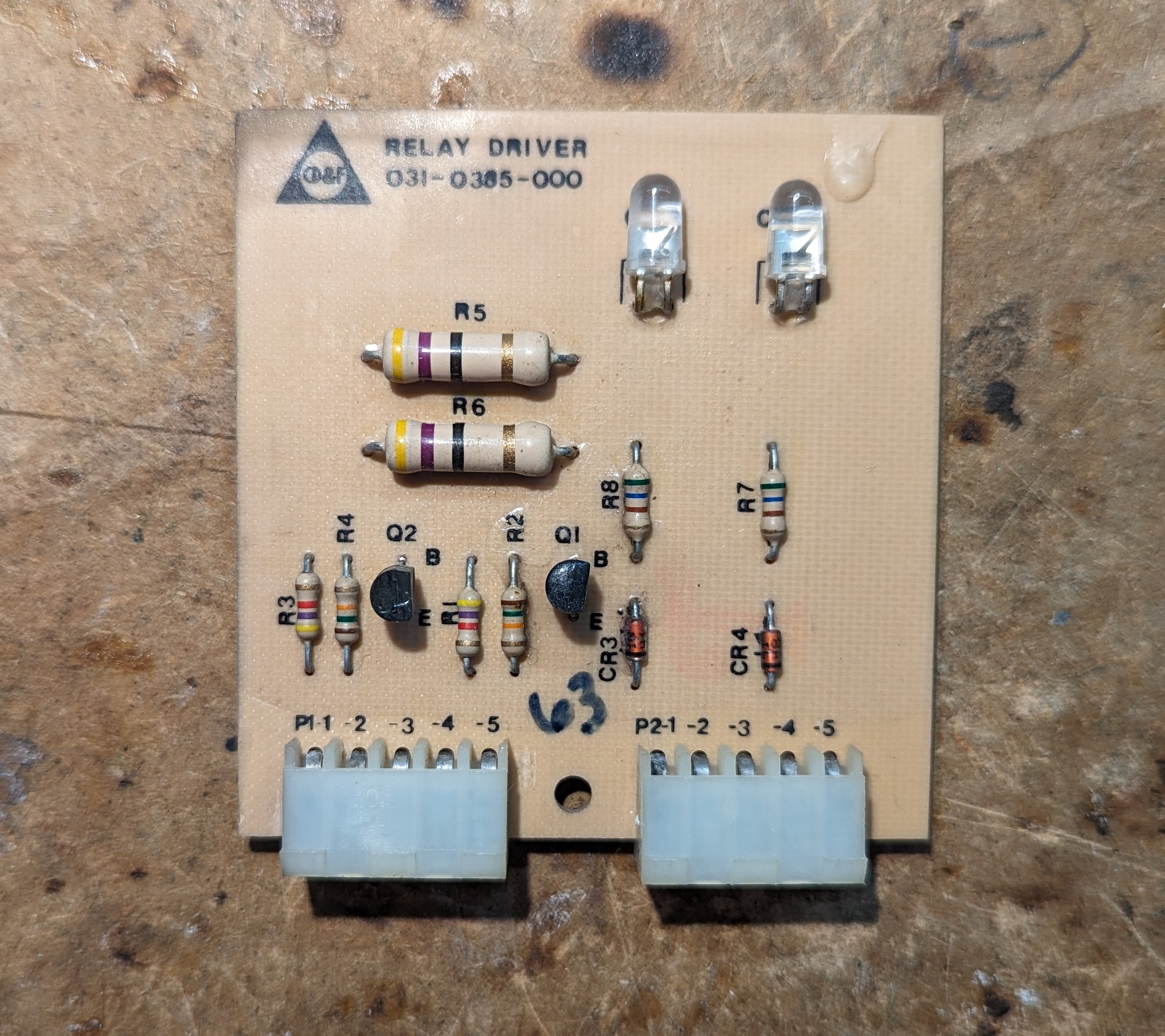
| 00:13, 17 April 2024 | Cdf relay driver top.jpg (file) |  |
1.32 MB | Relay driver board from the CD&F | 1 |
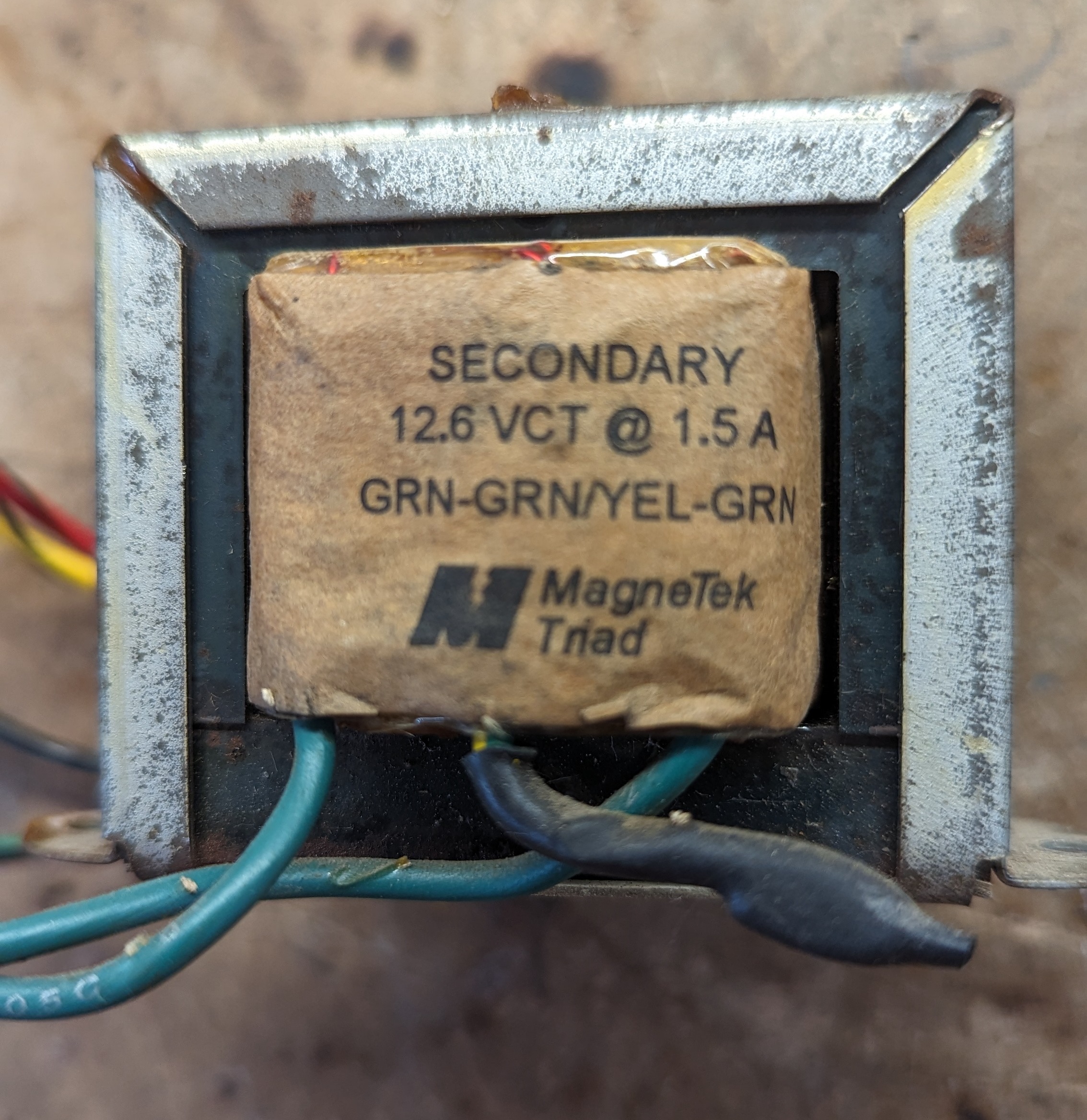
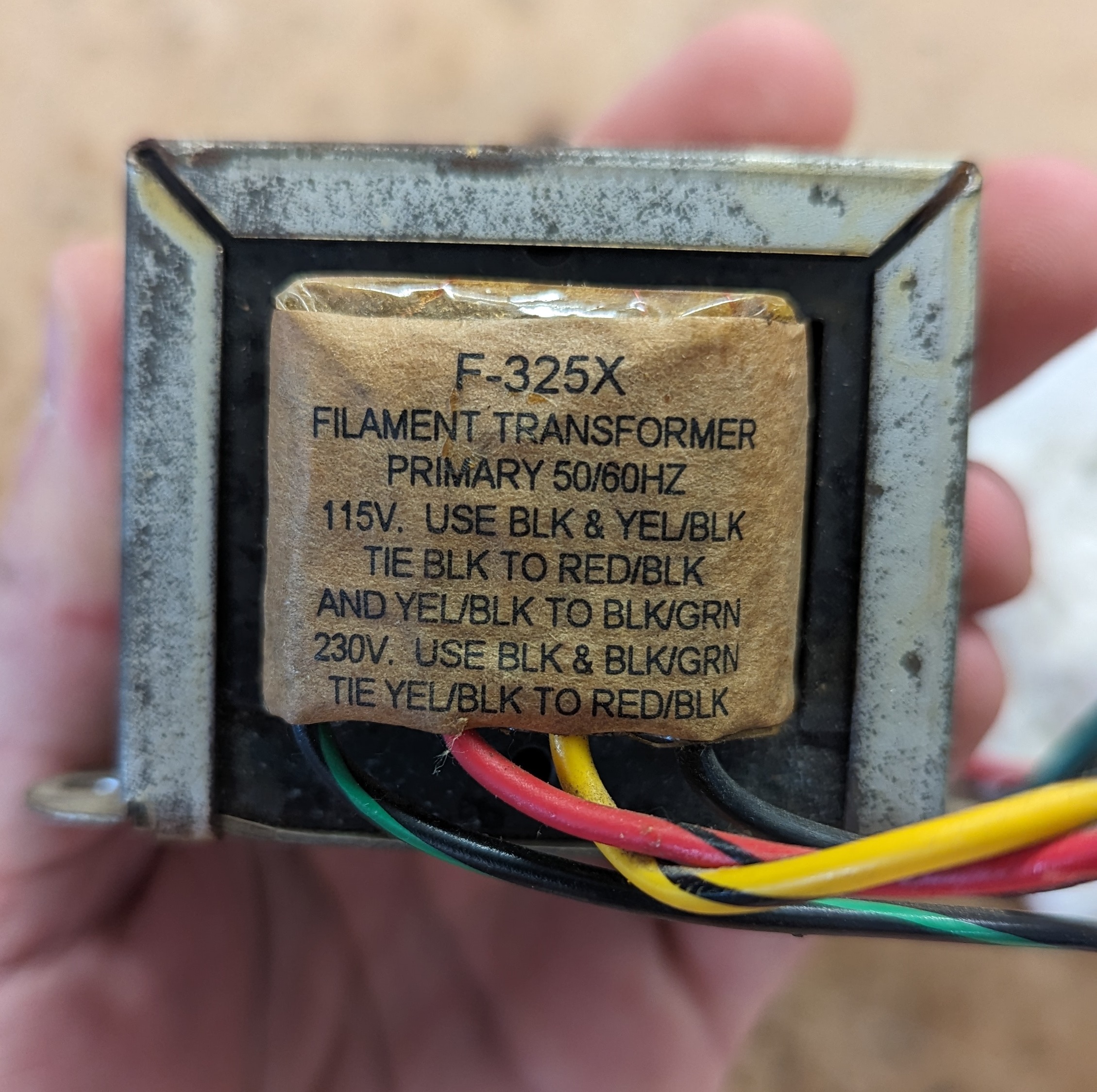
| 06:13, 15 April 2024 | Cdf xfmr sec.jpg (file) |  |
1.3 MB | Secondary of the CD&F transformer | 1 |
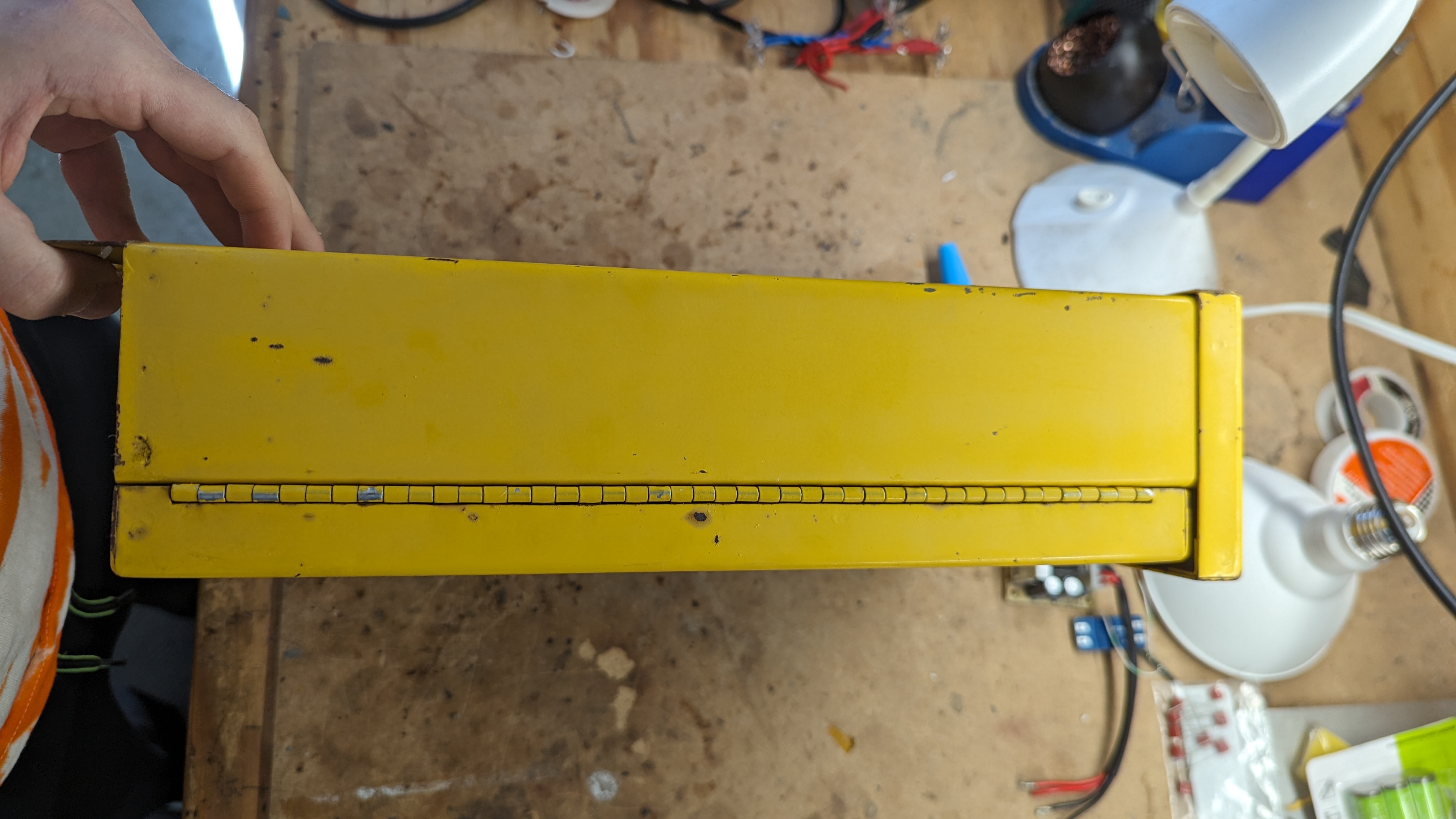
| 23:11, 15 April 2024 | Cdf hinge side.jpg (file) |  |
1.24 MB | Side of the enclosure with the hinge. The hinge cannot be removed from the door, but the door and hinge can be removed from the enclosure with three screws and nuts. | 1 |
| 06:01, 16 January 2023 | Dfm back pcb no battery.jpg (file) |  |
1.23 MB | 1 | |
| 23:10, 15 April 2024 | Cdf latch side.jpg (file) |  |
1.2 MB | Side of the enclosure with latch. First flips out, then rotate the wing to loosen the clamp. | 1 |
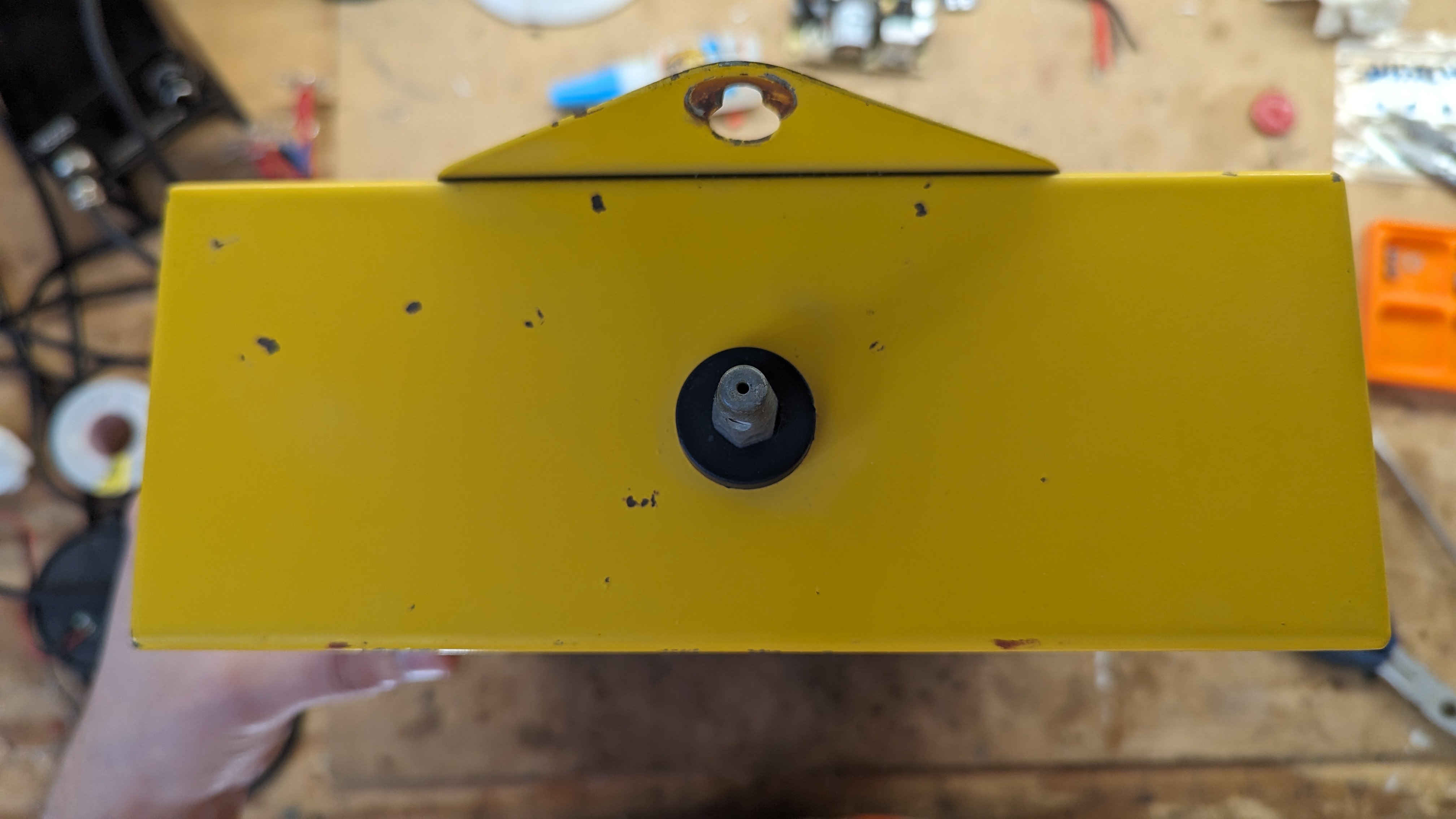
| 23:04, 15 April 2024 | Cdf top.jpg (file) |  |
1.18 MB | Top of the CD&F housing showing the antenna mount without the antenna | 1 |
| 06:13, 15 April 2024 | Cdf xfmr pri.jpg (file) |  |
1.18 MB | Cropped to fit better | 2 |
| 00:14, 17 April 2024 | Cdf relay driver back.jpg (file) |  |
1.17 MB | Backside of the relay driver board for the CD&F | 1 |
| 05:46, 15 April 2024 | Cdf front closed.jpg (file) |  |
1.03 MB | CD&F with the front door closed | 1 |