Xiaomi Roborock LIDAR: Difference between revisions
Jump to navigation
Jump to search
No edit summary |
|||
| (4 intermediate revisions by the same user not shown) | |||
| Line 1: | Line 1: | ||
[[File:Roborock_LIDAR.jpg|alt=| | [[File:Roborock_LIDAR.jpg|alt=|thumb|Xiaomi Roborock LIDAR]]LIDAR from the Xiaomi robotic vacuum, very similar in design to the one used in the Neato XV-11. | ||
<br /> | |||
==Teardown Video== | ==Teardown Video== | ||
| Line 6: | Line 8: | ||
<youtube width="320" height="240">aAFY8p1glmM</youtube> | <youtube width="320" height="240">aAFY8p1glmM</youtube> | ||
== | ==PCB Pictures== | ||
<gallery mode="packed-hover" heights="200"> | |||
File:Rubby CMOS MBV05-top.jpg|LIDAR CMOS sensor and DSP board - top side | |||
File:Rubby CMOS MBV05-bottom.jpg|LIDAR CMOS sensor and DSP board - bottom side (BENFEI connector to balance board for picture) | |||
File:Wireless Board-top.jpg|Wireless receiver board - top | |||
File:Wireless Board-Bottom.jpg|Wireless receiver board - bottom | |||
File:Power Board-top.jpg|Power board - top | |||
File:Power Board-Bottom.jpg|Power board - bottom | |||
File:Pinout.png|Pinout of connector on Power Board that connects to Roborock S5 | |||
</gallery> | |||
== | ==Mechanical Pictures== | ||
<gallery mode="packed-hover" heights="200"> | |||
File:Bearing Motor-side.jpg|DC Motor and Bearing | |||
File:Inductors.jpg|Inductors used for wireless power | |||
File:Laser Camera-front.jpg|Laser and Lens housing module, CMOS sensor board mounts to this | |||
File:Module Base-top.jpg|Base housing - top | |||
File:Module Base-bottom.jpg|Base housing - bottom | |||
File:Rotator-top.jpg|Rotating housing - top | |||
File:Rotator-bottom.jpg|Rotating housing - bottom | |||
File:Belt Shield-top.jpg|Belt and lens/laser hood | |||
</gallery> | |||
==Analysis of Hardware== | ==Analysis of Hardware== | ||
Latest revision as of 03:18, 22 October 2020

LIDAR from the Xiaomi robotic vacuum, very similar in design to the one used in the Neato XV-11.
Teardown Video
5 minute video showing all the parts of the LIDAR and how they go together, helps to understand all the parts and pieces pictured below.
PCB Pictures
-
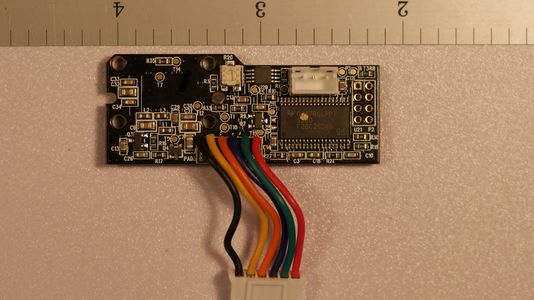 LIDAR CMOS sensor and DSP board - top side
 -
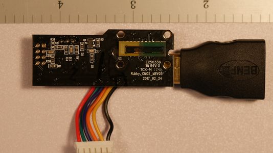 LIDAR CMOS sensor and DSP board - bottom side (BENFEI connector to balance board for picture)
 -
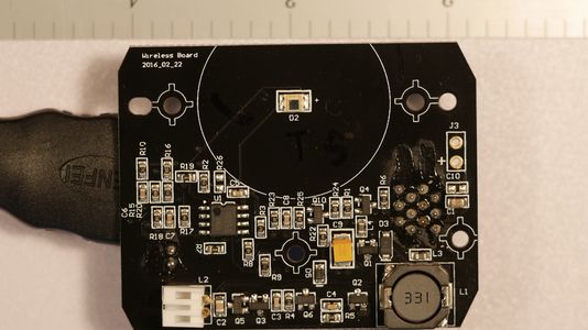 Wireless receiver board - top
 -
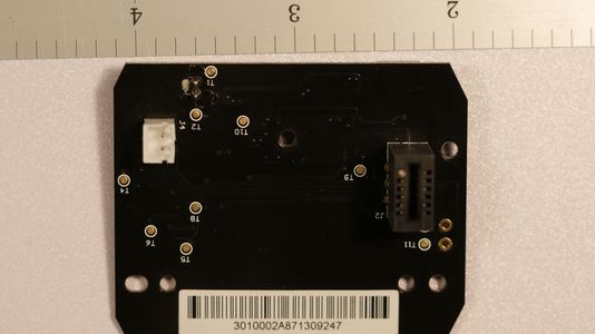 Wireless receiver board - bottom
 -
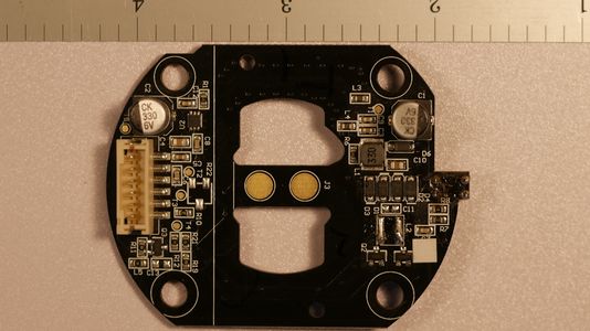 Power board - top
 -
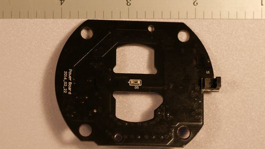 Power board - bottom
 -
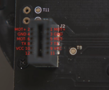 Pinout of connector on Power Board that connects to Roborock S5


Mechanical Pictures
-
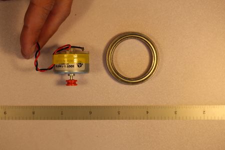 DC Motor and Bearing
 -
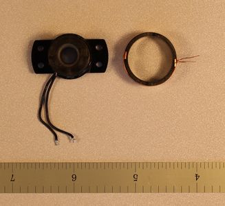 Inductors used for wireless power
 -
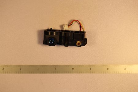 Laser and Lens housing module, CMOS sensor board mounts to this
 -
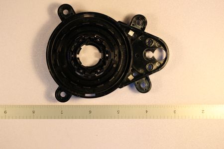 Base housing - top
 -
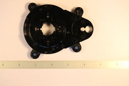 Base housing - bottom
 -
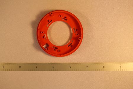 Rotating housing - top
 -
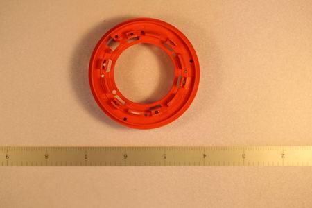 Rotating housing - bottom
 -
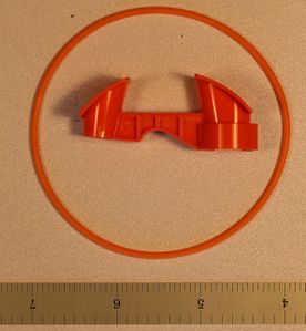 Belt and lens/laser hood


Analysis of Hardware
To be completed
Additional/Novel Uses
To be completed