Landis+Gyr Integrated WanGate Radio (IWR): Difference between revisions
Jump to navigation
Jump to search
→Series 4 Radio: Added notes to images |
|||
| (One intermediate revision by the same user not shown) | |||
| Line 1: | Line 1: | ||
<gallery> | <gallery mode="packed" heights="200"> | ||
File:Metricom Utilinet IWR Series II - Case External.jpg|Metricom Utilinet IWR Series II | File:Metricom Utilinet IWR Series II - Case External.jpg|Metricom Utilinet IWR Series II | ||
File:Metricom Utilinet IWR Series II - All Parts.jpg|Radio fully disassembled | File:Metricom Utilinet IWR Series II - All Parts.jpg|Radio fully disassembled | ||
| Line 10: | Line 10: | ||
===Series 4 Radio=== | ===Series 4 Radio=== | ||
<gallery> | <gallery mode="packed" heights="200"> | ||
File:LandisGyrWangateRadio1.JPG| Cellnet Technology Gridstream Series 4 | File:LandisGyrWangateRadio1.JPG|Cellnet Technology Gridstream Series 4 | ||
File:LandisGyrWangateRadio2.JPG| Smaller antenna connector than Series II radio, power connector moved to the other end of the case. | File:LandisGyrWangateRadio2.JPG|Smaller antenna connector than Series II radio, power connector moved to the other end of the case. | ||
File:LandisGyrWangateRadio3.JPG| Much smaller than Series II radio, more powerful processor and radio now uses single transceiver IC with increased transmission power. | File:LandisGyrWangateRadio3.JPG|Much smaller than Series II radio, more powerful processor and radio now uses single transceiver IC with increased transmission power. | ||
File:LandisGyrWangateRadio4.JPG| They still stick with a single sided PCB for component placement, same as Series II radio. | File:LandisGyrWangateRadio4.JPG|They still stick with a single sided PCB for component placement, same as Series II radio. | ||
</gallery> | </gallery> | ||
Latest revision as of 05:38, 27 December 2021
-
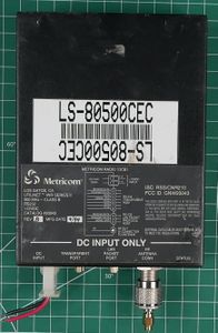 Metricom Utilinet IWR Series II
 -
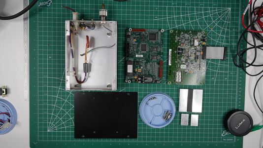 Radio fully disassembled
 -
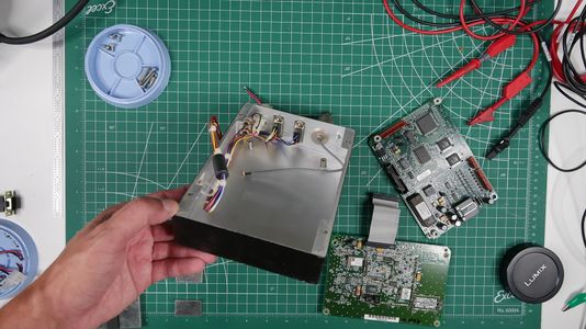 Internal view of case, notice surge suppressors bolted to the left side of the case.
 -
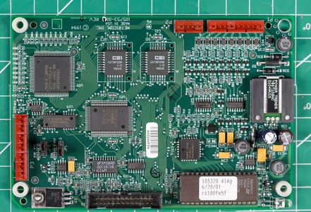 EEPROM for code storage and jumpers, JP2 used to enter test mode.
 -
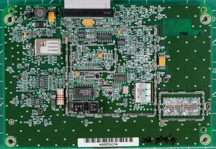 Radio transmitter/receiver board. Separate components used to build up RF circuit, replaced by single transceiver IC's in newer devices.


Series 4 Radio
-
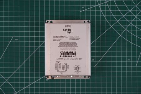 Cellnet Technology Gridstream Series 4
 -
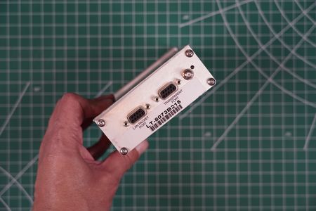 Smaller antenna connector than Series II radio, power connector moved to the other end of the case.
 -
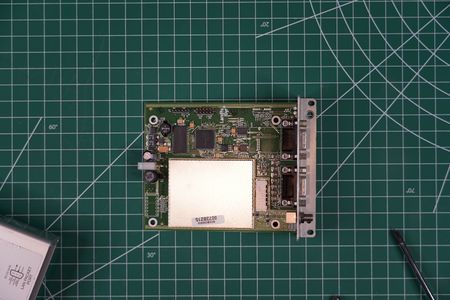 Much smaller than Series II radio, more powerful processor and radio now uses single transceiver IC with increased transmission power.
 -
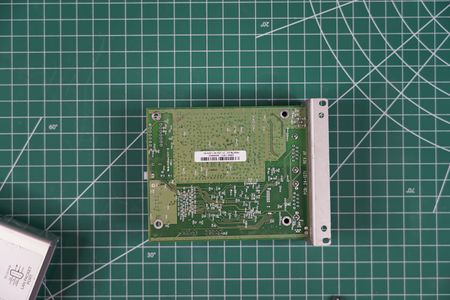 They still stick with a single sided PCB for component placement, same as Series II radio.


