Difference between revisions of "Maxon Data Radio"
(initial creation) |
m (Change image positioning) |
||
| Line 39: | Line 39: | ||
I contacted Maxon directly and their technical department emailed me a schematic for the out of production ACC-2016 interface cable. After making the circuit on a breadboard trying several times, and swapping TX/RX, I was not able to get the interface cable to work. Maybe you can, but I went for a more direct route. | I contacted Maxon directly and their technical department emailed me a schematic for the out of production ACC-2016 interface cable. After making the circuit on a breadboard trying several times, and swapping TX/RX, I was not able to get the interface cable to work. Maybe you can, but I went for a more direct route. | ||
| − | + | <gallery> | |
| − | + | File:Acc2016_schematic.png|thumb|250px|ACC-2016 Schematic | |
| + | </gallery> | ||
<br /> | <br /> | ||
| Line 73: | Line 74: | ||
** If you get things wrong and select a channel thats not programmed, the radio will flicker the red and green LEDs on boot. As long as you follow the black positions, you should be ok. | ** If you get things wrong and select a channel thats not programmed, the radio will flicker the red and green LEDs on boot. As long as you follow the black positions, you should be ok. | ||
| − | + | <gallery> | |
| − | + | File:Maxon_DIP_switch_config.png|thumb|250px|DIP switch configuration diagram | |
| + | </gallery> | ||
===Debugging=== | ===Debugging=== | ||
Here's a table of the status indications showing what the radio is doing, from the service manual page 18. There is plenty of other information in the service manual for troubleshooting and fixing that would be redundant to cover here, so make sure you give it a read. | Here's a table of the status indications showing what the radio is doing, from the service manual page 18. There is plenty of other information in the service manual for troubleshooting and fixing that would be redundant to cover here, so make sure you give it a read. | ||
| − | + | <gallery> | |
| − | + | File:Maxon_radio_status_chart.png|thumb|250px|Status chart from the serivice manual | |
| + | </gallery> | ||
==SD-125== | ==SD-125== | ||
Revision as of 02:51, 15 May 2024
Maxon America Inc. is a radio communications manufacturer headquartered in Lenexa, Kansas which makes a variety of Land Mobile Radios (LMR), Digital Mobile Radios (DMR), and original data telemetry modules.

Contents
Overview
Maxon data radios are a line of small radio transcievers developed for industrial telemetry and data reporting use. There are both analog and digital options, but here we will focus on the analog models.
Analog Models
- SD-125EL
- V2 - 5/1W VHF (148-174 MHz)
- U1 - 5/1W UHF (400-430 MHz)
- U2 - 5/1W UHF (440-470 MHz)
- SD-170EL
- SD-171EL - 5/1W VHF (146-174 MHz)
- SD-174EL - 5/1W UHF (450-490 MHz)
Older discontinued models:
- SD-161 - 2W VHF (148-174 MHz)
- SD-164 - 2W UHF (450-490 MHz)
- SD-171 - 5/1W VHF (148-174 MHz)
- SD-174 - 5/1W UHF (450-490 MHz)
SD-161
This is the model that I have, so any of the info I have below is from my experimentaton on this model. It may apply to at least the SD-164, and the SD-171/174 line as well but you are entering unknown territory.
Resources
Maxon America functions as a dealer, so as an individual you cannot buy direct from them nor can you create an account to download software. However, after some searching I was able to find a company that is a reseller for these radios and lists the software freely on their site. The company is called MobileTrends.ca
Programming (the hard way IMO)
These radios utilise a proprietary programming cable that converts RS-232 to TTL, as well as utilizing the RTS pin to control programming. That last part unfortunately prevents simply connecting TX and RX to a TTL to USB serial adapter...
I contacted Maxon directly and their technical department emailed me a schematic for the out of production ACC-2016 interface cable. After making the circuit on a breadboard trying several times, and swapping TX/RX, I was not able to get the interface cable to work. Maybe you can, but I went for a more direct route.
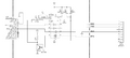
ACC-2016 Schematic

Programming (the easy way)
Inside the radio, there is a small 8 pin SOIC I2C EEPROM (Catalyst 24WC04) which stores all the programmed info. This chip can be easily read and written to using an inexpensive CH341a based programmer. The programming software (ACC-916E) shows a full EEPROM mapping in hex of the data to be written to the radio. With both of these, we can easily use the software to configure things as we want, then manually remake the hex file and flash it to the EEPROM.
- The first thing to do regardless of your plans is to back up the current state of the EEPROM with the CH341a. This file will also be a good base for modification when you change settings in the software. Save that file in a safe place, then make a copy for modding.
- Install the programming software which can be downloaded here and open it. Select "No Modem" and change your model
- You will need a serial port, be it in use or just a USB to serial adapter or virtual, just so the software will be happy and allow opening the R/W window
- Setup the channels with your desired info, you can (only tested on the SD-161 by me) go down into the ham bands. The software will let you force an out of band frequency, but from 147.5 and up, it won't say anything.
- "S" is Standard (25kHz) bandwidth, and "N" is Narrow (12.5kHz) bandwidth. Choose standard if you are using for amateur radio, otherwise narrow for business band use.
- Once you have channels setup, you could save the config to a file just for safe keeping, but thats not really needed.
- Click the W/R button on the topp nav bar to open the programming window. Here you will see the data to be written to the EEPROM.
- Open the copy of your backup in a hex editor like HxD and begin copying over the values from the preview window.
- Double check what you enter here! I have no idea how much damage a wrong byte could do!
- Once you have checked over your file, save it and load it into your programmer software and flash it to the EEPROM
- Do a read verify to make sure the EEPROM accepted the flashed contents
Channel Selection Switches
If everything went well so far, you should have your new config on your radio! One last thing to check is the channel DIP switches. The way maxon illustrated these is kinda confusing, but I figured it out.
- Open the radio if you haven't already, making sure the DB-15 and BNC port are facing up/away from you like the diagram shows.
- The correct way of interpreting the DIP configuration is that the switches on the board should match the BLACK areas on the diagrams. From there, its just a binary sequence.
- For example, channel 1 is all switches DOWN.
- If you get things wrong and select a channel thats not programmed, the radio will flicker the red and green LEDs on boot. As long as you follow the black positions, you should be ok.
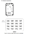
DIP switch configuration diagram

Debugging
Here's a table of the status indications showing what the radio is doing, from the service manual page 18. There is plenty of other information in the service manual for troubleshooting and fixing that would be redundant to cover here, so make sure you give it a read.
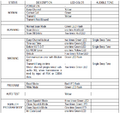
Status chart from the serivice manual

SD-125
Some time ago, a group of amateur radio operators have done similar research into programming the SD-125 for packet radio use on amateur frequencies. Their work can be found here.
The programming cable is similar, though uses a DB-9 serial port instead of the DB-15. I suspect you could program via EEPROM directly like I did as well.