Difference between revisions of "JTAGulator"
| (4 intermediate revisions by the same user not shown) | |||
| Line 1: | Line 1: | ||
The [http://www.grandideastudio.com/jtagulator/ JTAGulator] is an open source tool to help find On-Chip Debugging (OCD) interfaces. Designed by [[Joe Grand]] of [http://www.grandideastudio.com/ Grand Idea Studio] it can be used to find JTAG ports and UART's on embedded devices. | The [http://www.grandideastudio.com/jtagulator/ JTAGulator] is an open source tool to help find On-Chip Debugging (OCD) interfaces. Designed by [[Joe Grand]] of [http://www.grandideastudio.com/ Grand Idea Studio] it can be used to find JTAG ports and UART's on embedded devices. | ||
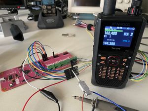
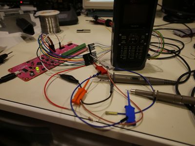
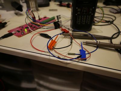
[[File:JTAGulator and Kenwood TH-D74.jpg|thumb|JTAGulator connected to a Kenwood TH-D74 to determine JTAG pinout|alt=|none]] | [[File:JTAGulator and Kenwood TH-D74.jpg|thumb|JTAGulator connected to a Kenwood TH-D74 to determine JTAG pinout|alt=|none]] | ||
| − | + | =Issue discovering JTAG lines and a work-around= | |
| − | |||
| − | |||
Initially hooking up the JTAGulator to the Kenwood TH-D74 amateur radio the JTAG pinout was not discovered. I figured perhaps the port I identified was incorrect or there may have been components removed disabling the JTAG port. I soldered wires to a completely different device that I verified with the components datasheet had JTAG and was indeed connected to the port I was using. Again, the JTAGulator did not identify the pinout. | Initially hooking up the JTAGulator to the Kenwood TH-D74 amateur radio the JTAG pinout was not discovered. I figured perhaps the port I identified was incorrect or there may have been components removed disabling the JTAG port. I soldered wires to a completely different device that I verified with the components datasheet had JTAG and was indeed connected to the port I was using. Again, the JTAGulator did not identify the pinout. | ||
I started running longer scans with the JTAGulator and probing each line with my oscilloscope to see what the waveform looked like. '''My hunch was correct, one of the data lines did not look like the rest!''' | I started running longer scans with the JTAGulator and probing each line with my oscilloscope to see what the waveform looked like. '''My hunch was correct, one of the data lines did not look like the rest!''' | ||
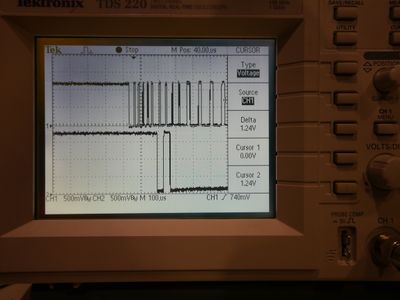
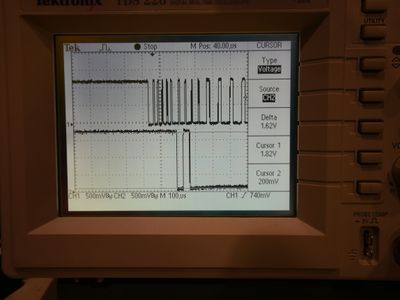
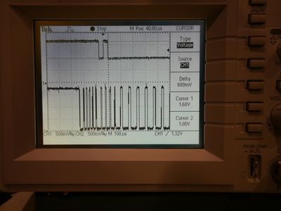
| − | On both devices I tested the TRST line was pulled low using a 2.2k resistor per the recommendations in the manufacturers datasheet. The JTAGulator does not seem able to drive these lines hard enough to overcome this resistor value.<gallery mode="packed | + | On both devices I tested the TRST line was pulled low using a 2.2k resistor per the recommendations in the manufacturers datasheet. The JTAGulator does not seem able to drive these lines hard enough to overcome this resistor value.<gallery mode="packed" heights="200"> |
File:1 TRST no pullup.jpg|Top waveform is TRST line being driven by JTAGulator, notice it only drives to about 1.24V and VCC is 1.8V so needs to be closer to that. | File:1 TRST no pullup.jpg|Top waveform is TRST line being driven by JTAGulator, notice it only drives to about 1.24V and VCC is 1.8V so needs to be closer to that. | ||
File:2 TRST no pullup.jpg|Bottom waveform is another line being driven by JTAGulator, notice it drives to about 1.62V and VCC is 1.8V so this is acceptable. | File:2 TRST no pullup.jpg|Bottom waveform is another line being driven by JTAGulator, notice it drives to about 1.62V and VCC is 1.8V so this is acceptable. | ||
Latest revision as of 03:16, 4 June 2020
The JTAGulator is an open source tool to help find On-Chip Debugging (OCD) interfaces. Designed by Joe Grand of Grand Idea Studio it can be used to find JTAG ports and UART's on embedded devices.
Issue discovering JTAG lines and a work-around
Initially hooking up the JTAGulator to the Kenwood TH-D74 amateur radio the JTAG pinout was not discovered. I figured perhaps the port I identified was incorrect or there may have been components removed disabling the JTAG port. I soldered wires to a completely different device that I verified with the components datasheet had JTAG and was indeed connected to the port I was using. Again, the JTAGulator did not identify the pinout.
I started running longer scans with the JTAGulator and probing each line with my oscilloscope to see what the waveform looked like. My hunch was correct, one of the data lines did not look like the rest!
On both devices I tested the TRST line was pulled low using a 2.2k resistor per the recommendations in the manufacturers datasheet. The JTAGulator does not seem able to drive these lines hard enough to overcome this resistor value.
