Difference between revisions of "Xiaomi Roborock LIDAR"
Jump to navigation
Jump to search
| Line 5: | Line 5: | ||
<br /> | <br /> | ||
<youtube width="320" height="240">aAFY8p1glmM</youtube> | <youtube width="320" height="240">aAFY8p1glmM</youtube> | ||
| + | |||
| + | == Teardown PCB Pictures == | ||
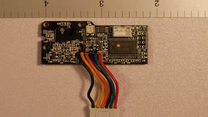
| + | [[File:Rubby CMOS MBV05-top.jpg|none|thumb|LIDAR CMOS sensor and DSP board - top side]] | ||
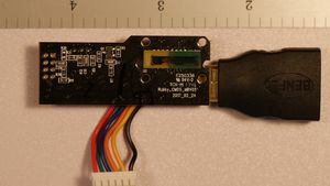
| + | [[File:Rubby CMOS MBV05-bottom.jpg|none|thumb|LIDAR CMOS sensor and DSP board - bottom side (don’t mind the BENFEI connector on the right side, used to steady PCB for picture)]] | ||
| + | <br /> | ||
Revision as of 17:23, 26 April 2020
File:Roborock LIDAR.png
Xiaomi Roborock LIDAR module
Teardown Video
5 minute video showing all the parts of the LIDAR and how they go together, helps to understand all the parts and pieces pictured below.
Teardown PCB Pictures

