CD&F (Siren Controller): Difference between revisions
m add a linebreak |
Add info about discovered DTMF modules and fix some numbering issues |
||
| (One intermediate revision by the same user not shown) | |||
| Line 189: | Line 189: | ||
'''U1''' - Motorola MC14069UBCP<ref>https://www.mouser.com/datasheet/2/308/1/MC14069UB_D-2315482.pdf</ref> (Hex Inverter) | '''U1''' - Motorola MC14069UBCP<ref>https://www.mouser.com/datasheet/2/308/1/MC14069UB_D-2315482.pdf</ref> (Hex Inverter) | ||
*Modern replacement - TI CD4069UBE<ref>https://www.ti.com/lit/ds/symlink/cd4069ub.pdf</ref> | |||
'''U2''' - Motorola MC14050BCP<ref>https://www.mouser.com/datasheet/2/308/1/mc14049b_d-1193035.pdf</ref> (Hex Buffer) | '''U2''' - Motorola MC14050BCP<ref>https://www.mouser.com/datasheet/2/308/1/mc14049b_d-1193035.pdf</ref> (Hex Buffer) | ||
*Modern replacement - TI CD4050BE<ref>https://www.ti.com/lit/ds/symlink/cd4050b.pdf</ref> | |||
'''U3''' - Motorola MC14073BCP<ref>https://www.mouser.com/datasheet/2/308/1/MC14001B_D-2315187.pdf</ref> (B-Series Triple 3−Input AND Gate) | '''U3''' - Motorola MC14073BCP<ref>https://www.mouser.com/datasheet/2/308/1/MC14001B_D-2315187.pdf</ref> (B-Series Triple 3−Input AND Gate) | ||
*Modern replacement - TI CD4073BE<ref>https://www.ti.com/lit/ds/symlink/cd4073b.pdf</ref> | |||
'''U4''' - Motorola MC1455P1<ref>https://www.onsemi.com/pdf/datasheet/mc1455-d.pdf</ref> (555 Timer) | '''U4''' - Motorola MC1455P1<ref>https://www.onsemi.com/pdf/datasheet/mc1455-d.pdf</ref> (555 Timer) | ||
*Modern replacement - NE555P/LM555CN | |||
| Line 228: | Line 235: | ||
!Function | !Function | ||
|- | |- | ||
|''' | |'''P2-1''' | ||
|GND | |GND | ||
|- | |- | ||
|''' | |'''P2-2''' | ||
|Output, goes to programming section | |Output, goes to programming section | ||
|- | |- | ||
|''' | |'''P2-3''' | ||
|Input, goes to programming section | |Input, goes to programming section | ||
|- | |- | ||
|''' | |'''P2-4''' | ||
|Output to Timer, thru diode customization section between decoders (CR5 & CR8) | |Output to Timer, thru diode customization section between decoders (CR5 & CR8) | ||
|- | |- | ||
|''' | |'''P2-5''' | ||
|From CR5 diode, test output? (N/C on main board) | |From CR5 diode, test output? (N/C on main board) | ||
|} | |} | ||
| Line 351: | Line 358: | ||
====Converting a Steady Timer to a CD Cycle Timer==== | ====Converting a Steady Timer to a CD Cycle Timer==== | ||
With a bit of patience and the missing components detailed in the manual, one could theoretically turn a CD steady timer into a CD Cycle/Fire timer. | With a bit of patience and the missing components detailed in the manual, one could theoretically turn a CD steady timer into a CD Cycle/Fire timer. | ||
Do note however that if you do so, you must cut or desolder the jumper in the W1 position. | Do note however that if you do so, you must cut or desolder the jumper in the W1 position. | ||
=====Caveats===== | |||
Unfortunately, you cannot just replace W1 with a switch. If you attempt to do so, the timer will start and latch for the duration of the first attack cycle, then turn off, then the output of U2 will go into oscillation. After some experimentation however, if you bend pin 3 of U3 up and install a second switch that switches pin 3 to its pad, then you can control what mode the timer operates in. | |||
*W1 "off" and U3 pin 3 "on" - CD Cycle functionality | |||
*W2 "on" and U3 pin 3 "off" - CD Steady functionality | |||
---- | |||
| Line 371: | Line 392: | ||
'''U1''' - Motorola MC14081BCP<ref>https://www.mouser.com/datasheet/2/308/1/MC14001B_D-2315187.pdf</ref> (B-Series CMOS Quad 2−Input AND Gate) | '''U1''' - Motorola MC14081BCP<ref>https://www.mouser.com/datasheet/2/308/1/MC14001B_D-2315187.pdf</ref> (B-Series CMOS Quad 2−Input AND Gate) | ||
*Modern replacement - TI CD4081BE<ref>https://www.ti.com/lit/ds/symlink/cd4073b.pdf</ref> | |||
'''U2''' - Motorola MC14011BCP<ref>https://www.mouser.com/datasheet/2/308/1/MC14001B_D-2315187.pdf</ref> (B-Series CMOS Quad 2−Input NAND Gate) | '''U2''' - Motorola MC14011BCP<ref>https://www.mouser.com/datasheet/2/308/1/MC14001B_D-2315187.pdf</ref> (B-Series CMOS Quad 2−Input NAND Gate) | ||
*Modern replacement - TI CD4011BE<ref>https://www.ti.com/lit/ds/symlink/cd4011b.pdf</ref> | |||
'''U3''' - Motorola MC1455P1<ref>https://www.onsemi.com/pdf/datasheet/mc1455-d.pdf</ref> (555 Timer) [ONLY PRESENT ON CD CYCLE/FIRE MODELS] | '''U3''' - Motorola MC1455P1<ref>https://www.onsemi.com/pdf/datasheet/mc1455-d.pdf</ref> (555 Timer) [ONLY PRESENT ON CD CYCLE/FIRE MODELS] | ||
*Modern replacement - NE555P/LM555CN | |||
'''U4''' - Maxim ICM7240IPE<ref>https://www.analog.com/media/jp/technical-documentation/data-sheets/1360.pdf</ref> (Programmable Timer/Counter IC) | '''U4''' - Maxim ICM7240IPE<ref>https://www.analog.com/media/jp/technical-documentation/data-sheets/1360.pdf</ref> (Programmable Timer/Counter IC) | ||
*Modern replacement - ICM7250IPE+ ($10/chip!) | |||
| Line 438: | Line 466: | ||
---- | ---- | ||
===Relay Driver Module=== | ===Relay Driver Module=== | ||
| Line 521: | Line 548: | ||
* [https://www.mouser.com/catalog/645/usd/1631.pdf Molex KK series headers datasheet] | * [https://www.mouser.com/catalog/645/usd/1631.pdf Molex KK series headers datasheet] | ||
The modern verison of these seems to be the molex [https://www.molex.com/en-us/products/connectors/wire-to-board-connectors/kk-connectors KK 396 series.] Same shapes, different material (nylon vs polyester(!)) | |||
==Programming== | ==Programming== | ||
| Line 1,003: | Line 1,032: | ||
<br /> | <br /> | ||
===DTMF Tone Decoders=== | |||
I recently became aware that at some point, CD&F made DTMF decoders that use the two tone decoder PCB and have a Norcomm NC401 module attached to them. The manual for the module can be [[:File:Norcommnc401.pdf|viewed here.]] Its based on an 8051 mcu and the classic MT8870 DTMF decoder IC. You can program various functionality and digit sequences into it. | |||
<gallery> | |||
File:Cdf_decoder_dtmf.jpg|An example of a DTMF decoder card | |||
</gallery> | |||
| Line 1,024: | Line 1,060: | ||
*These devices are quite old, and excessive handling and stress seems to not play nice to the solder joints. I have fixed both the tone filters and receiver section by reflowing every joint with leaded solder. | *These devices are quite old, and excessive handling and stress seems to not play nice to the solder joints. I have fixed both the tone filters and receiver section by reflowing every joint with leaded solder. | ||
*Due to the XR2211A IC being obsolete and quite hard to source nowadays, I may try to design my own tone decoder board using the LM567 IC which is still available in SMD form factors. The LM567 also outputs a logic low when signal is detected, but the design will have to incorperate a LDO 5v regulator to power the chip from the 12v the cards get. | *Due to the XR2211A IC being obsolete and quite hard to source nowadays, I may try to design my own tone decoder board using the LM567 IC which is still available in SMD form factors. The LM567 also outputs a logic low when signal is detected, but the design will have to incorperate a LDO 5v regulator to power the chip from the 12v the cards get. | ||
*Similarly, many of the ICs are obsolete nowadays, though some have replacements. The main Maxin timer IC is absurdly expensive per chip, so I may redesign the entire thing. | |||
*I have not adjusted any of the filter components on the receiver circuit yet, but I did run an experiment by leaving the device plugged in with the antenna attached inside my house while sending the activation signal from a few dense suburban blocks away. The board operated perfectly with 5W from my Anytone 878, turning on and off. | *I have not adjusted any of the filter components on the receiver circuit yet, but I did run an experiment by leaving the device plugged in with the antenna attached inside my house while sending the activation signal from a few dense suburban blocks away. The board operated perfectly with 5W from my Anytone 878, turning on and off. | ||
*While the tone filters are labled J1 thru J6 on the PCB, the actual numbering is reversed, tone filter 1 is at the top and 6 is at the bottom. Despite that, my unit (and I suspect others that were reconfigured by a third party) may not start at slot 1. My unit has slots 6, 5, and 4 occupied with the corresponding wiring on the programming board. The nameplate implies slots 1, 2, and 3 however. Overall it doesn't ''really'' matter if things aren't in numerical order, but it sure as hell makes things confusing... | *While the tone filters are labled J1 thru J6 on the PCB, the actual numbering is reversed, tone filter 1 is at the top and 6 is at the bottom. Despite that, my unit (and I suspect others that were reconfigured by a third party) may not start at slot 1. My unit has slots 6, 5, and 4 occupied with the corresponding wiring on the programming board. The nameplate implies slots 1, 2, and 3 however. Overall it doesn't ''really'' matter if things aren't in numerical order, but it sure as hell makes things confusing... | ||
*On the maxon data radio DB-15 connector, you can solder a normal speaker to pin | *On the maxon data radio DB-15 connector, you can solder a normal speaker to pin 9 and GND (4) to monitor the recieve audio. You can adjust volume with RV401 onboard inside the radio, or just use an inline resistor if you are lazy. | ||
<br /> | <br /> | ||
Latest revision as of 02:10, 17 August 2024
Civil Defense & Fire (CD&F) siren controllers function on two-tone Motorola QuikCall, Plectron, or General Electric style paging to wirelessly activate warning sirens. The device can be activated via radio or locally via dry contacts. Not much is known about these devices or the company nowadays, but here is what I have discovered.
Overview & Goals
Contrary to modern offerings like the FC from Federal Signal[1], these devices are simple two-tone paging decoders that listen at a fixed radio frequency (VHF high or low band) and activate a relay on a timer when the correct signal is sent. There are also provisions for push button activation or remote non-RF activation via telephone relay with dry contacts. These controllers tended to be known by siren enthusiasts as unreliable and flaky, though I have theories on why that is later on. Regardless, they are completely analog in circuitry which offers some relative simplicity in understanding and reverse engineering.
My goals in experimentation and reverse engineering this thing are as follows:
- Retune the onboard radio receiver to function within the 2 meter amateur radio band instead of the VHF high band my unit is configured for.
- Reverse engineer and document the functionality of the tone decoding circuitry and determine the maximum and minimum limits for the tone frequencies based on the onboard components.
Recreate schematics of each daughterboard to help with figuring out their functionality.Shown in the manualDocument the theory of operation and create a rough block diagram for functionality.Shown in the manual- Document any theories, issues that arise and their fixes, as well as things to watch out for
- Design a new tone decoder daughterboard using more common components (LM567)
- Recreate timer PCB to allow for additional signals to be added to models without extra timers
- Design and add a small audio amplifier circuit and speaker to listen to the recevier audio feed locally (LCRx only)
History
Not much information is available about these devices on the internet unfortunately, as they were more commonplace back in the 1980's and 1990's. Despite that, there are many units that were shipped into the mid 2000's, and the company was merged/acquired by Sentry Siren sometime in the mid 2010's. The company, however, was located at 140 North Tyler Street in Elm Creek, Nebraska. The company was registered with the FCC on 4/14/98 by a R. E. Kugler. Some municipalities still have these devices deployed in old systems because "if it ain't broke, don't fix it" always prevails of course. There appears to exist at least 3 types that I have personally seen online including my own unit. The most I have discovered amounts to what I have seen regarding FCC filings from the 1986 to 1990 under the company name (under grantee code F49[2]) and what I have seen in various sources of media from Google images and YouTube videos. The FCC ID's associated with F49 are as follows:
- F49LCR-2[3] registered on 02/09/90 with an operating frequency range of 150-174 MHz
- F49LCR-1[4] registered on 02/09/90 with an operating frequency range of 25-50 MHz
- F49EMR-3[5] registered on 02/09/90 with an operating frequency range of 130-148 MHz
- F49EMR-2[6] registered on 02/09/90 with an operating frequency range of 148-174 MHz (Possibly suggests use of Maxon Data Radio?)
- F49EMR-1[7] registered on 02/09/90 with an operating frequency range of 25-54 MHz
- F49CDF-2[8] registered on 02/09/90 with an operating frequency range of 148-174 MHz(Possibly suggests use of Maxon Data Radio?)
- F49CDF-1[9] registered on 02/09/90 with an operating frequency range of 25-54 MHz
- F498POCDF-3[10] Not registered on FCC database, but exists. UHF variant of SC series (SC3)
- F498POCDF-2[11] registered on 02/09/90 with an operating frequency range of 148-174 MHz (Possibly suggests use of Maxon Data Radio?)
- F498POCDF-1[12] registered on 02/09/90 with an operating frequency range of 25-54 MHz
My unit is marked F49LCR-2 and is tuned for 152.240 MHz.
Speculation
My current research shows the existence of at least two or three types of these devices. Obviously there are more devices produced by the company, but I have zero clue what they are.
- This model that I own, which is always civil defense yellow and measures 325x232x92mm a few times on the internet in videos and photos
- Appears to always have it's radio receiver on the motherboard with descrete components.
- A larger more rectangular one, which I have acquired (yay!) that can be either silver or civil defense yellow.
- This unit is even more modular and can contain either a descrete radio receiver board, some kind of descrete but shielded radio board, or a maxon data radio board (which is reprogrammable)
- These units have built-in local activation buttons and no terminals for remote activation. Just AC in and one or two relay contacts
- These units also can do multiple signals including alert (steady), attack (wail), and fire (not quite sure what it means, fast wail maybe?) and have more tone decoders and timer cards
- I've also noticed a possibly earlier variant that has a screw latch instead of a folding wing type latch.
My large silver unit does not appear to have an FCC ID. This kinda makes sense since the only RF part is a pre-certified radio receiver
I have also noticed at least one unit that has the "PO" of F49POCDF markered out, which would make it F49CDF, which is a vaild ID. I believe that F49CDF and F49POCDF may be the same units with just a different variation or newer/older models.
CD&F makes other products as well, though the only other example I have seen is some sort of electronic siren controller on Twitter (LINK HERE)
This section contains part descriptions and information that is relevant across the entire line of controllers.
Manual
I was given a scanned copy of a manual for the SC line of controllers, though there is plenty of info relevant to all models within. I have uploaded it to archive.org here.
Naming/Serial Convention
According to the manual, this is how the controller units are named. At least, the larger SC variants. Some older units seem to follow slightly different conventions (ex. SC3M0-1322)
SC(V)-(W)-(XY)-(ZZZZ)
SC - Siren Controller
V - Frequency band
- 1 - Low Band VHF (30-50MHz)
- 2 - High Band VHF (148-173MHz)
- 3 - UHF (440-480MHz)
W - ???
X - Tone format & timing
- P - Plectron
- M - Motorola
- G - General Electric
- F - ??? (Mentioned in manual, Maybe Motorola 4 tone?)
Y - Revision number
Z - Serial Number
This is how I interpreted it, though I could be wrong about the revision number placement.
Tone Filters
The tone filters are simple little daughterboards based on the Exar/MaxLinear XR2211ACP[13] FSK/Tone decoder IC. The board contains the necessary passive components to enable tone decode functionality of the IC. Audio comes in from the recieve circuit on pin P1 and runs through the IC. When a tone matched the configured settings, the receiver module drops pin P4 low, otherwise it is held high. Thats pretty much it. The variable resistor is used to change the set frequency of the module, but I do not know to what extent yet. Testing needs to be done.
Example values for my tones are as follows:
- A1 (1153.4 Hz): 5.747kOhms
- A2 (1285.8 Hz) 4.9 to 5kOhms, contact was rough
-
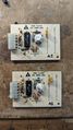 Tone filters top side
 -
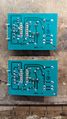 Tone Filters bottom side (mirrored to match top side)


|
Tuning
Tuning the onboard pots was a little odd at first, but it appears CCW is higher frequency, CW is lower frequency. It seems that out of circuit (or at least with my crackpot test setup) the logic NOT output of the chip appeared to not function. I thought I had broken the chip at first, but after using the standard logic output to retune back to the original frequency, things worked when back in the main board. So, moral of the story is to use the standard logic output when tuning and just be careful. Looking at the datasheet for the XR2211A, the signal input on pin 2 can be anywhere from 10mV RMS to 3V RMS which is quite nice. Keep that in mind when injecting a signal from a function generator.
Searching for tone filter max/min/current frequency
I tested filter A2 and the highest seems to be ~1.44kHz and lowest at ~1.12kHz with its components. I suspect that due to this small range, there may be either multiple model numbers (other than 031-0392-000) which have slightly different component values or possibly a different potentiometer. One other possibility is that this model just cant go outside those ranges, but I highly doubt that since many times these has to work with existing fire department/police department paging systems.
With that being said, you may want to test your own filters. Here is how I tested mine:
- Hook up your function generator or audio source (pure sine wave) on pin P1, VCC (12v DC) on pin P2, GND on P3, and your oscilloscope or voltmeter on pin P5.
- You may also want to hook a second oscilloscope channel to the function generator output.
- Without touching the onboard pot, slowly sweep through frequencies from about 300Hz to 2.5kHz. Most paging systems are probably within these.
- Watch for the logic output of the filter to go high, indicating you have found the proper frequency.
- There is a certain amount of passband in the filter, so tune back and forth slowly around the points where the filter triggers to find the upper and lower bounds, then you can calculate the approximate center frequency from there.
- You may want to re-silicone the pot and also mark the set frequency on the PCB in marker.
Tuning filters to a different frequency
If you aren't searching for the frequency bounds like I was, I suggest tuning the filters in the following way:
- Hook up your function generator or audio source (pure sine wave) on pin P1, VCC (12v DC) on pin P2, GND on P3, and your oscilloscope or voltmeter on pin P5.
- You may also want to hook a second oscilloscope channel to the function generator output.
- Turn on your function generator and set it to the frequency you wish for the module to respond to.
- If you haven't already, dig the silicone out of the pot and make sure its clean. VERY slowly rotate CCW for a higher frequency or CW for a lower frequency.
- Once you have the pot tuned properly, the logic output of the filter will go high. You are within the bandwidth of the filter now.
- Test the bandwidth by changing frequency slightly above and below your desired set point. Slowly adjust the pot to center in the passband to your desired frequency.
- You may want to re-silicone the pot and also mark the set frequency on the PCB in marker.
Through some component changes, you will probably be able to change the adjustable range of the filters. That is something I am going to investigate soon.
Tone filter troubleshooting
If you suspect the tone filters are not functioning properly, check that you have installed them in the correct order and are running the right sequence of tones through the unit. If that fails, I have encountered issues with the main board as well as these modules that required reflowing all solder joints due to being brittle and most likely cracking and making poor connections.
Do be aware, on the mainboard and parts of the tone decoders there is conformal coating. Acetone or MEK should help remove this. I suggest removing before soldering to not contaminate the solder joints
Decoder Modules
The decoder modules take in the logic low pulses from the tone filters and use some logic circuitry to eventually send a signal to the timer module to start a cycle.
ICs:
U1 - Motorola MC14069UBCP[14] (Hex Inverter)
- Modern replacement - TI CD4069UBE[15]
U2 - Motorola MC14050BCP[16] (Hex Buffer)
- Modern replacement - TI CD4050BE[17]
U3 - Motorola MC14073BCP[18] (B-Series Triple 3−Input AND Gate)
- Modern replacement - TI CD4073BE[19]
U4 - Motorola MC1455P1[20] (555 Timer)
- Modern replacement - NE555P/LM555CN
|
|
-
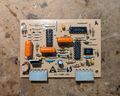 Decoder modules topside
 -
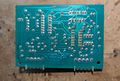 Decoder modules bottom side (mirrored to match top side)


Timer Modules
More examination needs to be done, but this module appears to latch the relay for a configured amount of time. I have seen multiple of these on other models that can do more signals such as "Attack" or "Fire", some with more DIP switches populated. The covered DIP switches of SW1 control parameters of the timing cycle, feeding configuring the 8 bits of the Maxim timer IC. Those bits configure the time delay by connecting each of the pins 1 through 8 on the IC through the a 10kOhm resistor (R3) to VCC.
DIP Switch Config
SW1 (Total Time)
The stock DIP switch config for the steady 3 min cycle timer is, from left to right (Up = ON): up, down, up, down, down, up, down, up. This sets pins 1, 3, 6 and 8 high, and 2,4,5,and 7 low (the DIP switch numbers are backwards in reference to the IC pins). This equates to a RC time constant of 165.
According to the manual, SW1 controls the total time that the function is activated with a +/- 10% margin. The switches add together in a binary sequence when closed (up)
|
An example shown in the manual is switches 1, 3, 4, and 6 closed, providing a run time of 3 minutes (180s).
SW2 & SW3 (On/Off time during cycle)
On CD cycle/fire timers, the addition of ommitted components and SW2/SW3 allows for controlling the time spent on and off during the total cycle time defined by SW1. These switches add up in a binary sequence when open (down) with a +/- 10% margin.
- SW2 controls the time spent ON during a cycle
- SW3 controls the time spent OFF during a cycle
|
Converting a Steady Timer to a CD Cycle Timer
With a bit of patience and the missing components detailed in the manual, one could theoretically turn a CD steady timer into a CD Cycle/Fire timer.
Do note however that if you do so, you must cut or desolder the jumper in the W1 position.
Caveats
Unfortunately, you cannot just replace W1 with a switch. If you attempt to do so, the timer will start and latch for the duration of the first attack cycle, then turn off, then the output of U2 will go into oscillation. After some experimentation however, if you bend pin 3 of U3 up and install a second switch that switches pin 3 to its pad, then you can control what mode the timer operates in.
- W1 "off" and U3 pin 3 "on" - CD Cycle functionality
- W2 "on" and U3 pin 3 "off" - CD Steady functionality
-
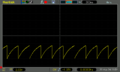 Wide view of the RC oscillator via pin 13
 -
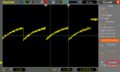 Decoder modules bottom side (mirrored to match top side)


At low values it seems to be pretty accurate (eg. 5 sec), but with my test of "180s" (8, 6, 5 and 4 high) yielded approximately 3m18s (almost 200s). Timing the stock setting gets 2m57s, or 177s. This is consistent with the stated +/- 10% margin.
ICs (Steady Cycle Timer 031-0389-000):
U1 - Motorola MC14081BCP[21] (B-Series CMOS Quad 2−Input AND Gate)
- Modern replacement - TI CD4081BE[22]
U2 - Motorola MC14011BCP[23] (B-Series CMOS Quad 2−Input NAND Gate)
- Modern replacement - TI CD4011BE[24]
U3 - Motorola MC1455P1[25] (555 Timer) [ONLY PRESENT ON CD CYCLE/FIRE MODELS]
- Modern replacement - NE555P/LM555CN
U4 - Maxim ICM7240IPE[26] (Programmable Timer/Counter IC)
- Modern replacement - ICM7250IPE+ ($10/chip!)
|
|
-
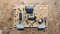 Timer module topside
 -
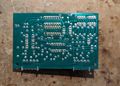 Timer module bottom side (mirrored to match top side)


Relay Driver Module
The relay driver is super simple, consisting of just 2 transistors (NTE85 and 2N3414), some resistors and 2 diodes. Not to mention the two LEDs as well. The whole purpose of the driver seems to be level shifting and driving the coil using the main DC supply of the board. Not much else to it.
-
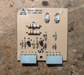 Relay module topside
 -
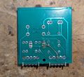 Relay module bottom side (mirrored to match top side)
 -
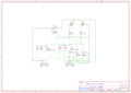 Reverse engineered schematic of the relay driver.


|
|
I/O connector pinout
This connector is the one just left of the relay. Houses the relay wires and the start/stop button inputs.
- E10: Relay Coil
- E9: Relay Coil
- E8: Start terminal
- E7: Stop terminal
- E6: Common terminal
Board Connectors
The molex connectors that are used on all the modular boards are Molex KK series with a .156" pitch.
The modern verison of these seems to be the molex KK 396 series. Same shapes, different material (nylon vs polyester(!))
Programming
There are two small sections below the tone decoders and inbetween the two decoder boards that allow for changing the path of signals in and out of the decoder boards. This allows for changing the behavior of the unit depending on the number of tone filters installed.
For example, my unit has two filters installed and the "on" sequence is A1, A2 (1153/1285 Hz), and "off" is the opposite. Since there are 4 card positions, you can also configure a 3 and 4 card setup
2 Card Setup
Probably the most common, and what my unit is configured for. Sending A1, A2 turns the unit on, and A2, A1 turns it off. The jumpers are configured as follows:
- CR1 diode from 1 to A1
- CR2 diode from 2 to A2
- B1 to A2 jumper (in row 3)
- A1 to B2 jumper (in row 4)
- CR5 in place facing the board marking
- CR6 empty
- CR7 empty
- CR8 in place facing the board marking
3 Card Setup
One tone filter is a "common" tone, and the other two are completely different frequencies. If for example, 800 Hz is the common tone and the others are 740 and 930, then one could configure the unit to turn on with 800/740, and off with 800/930.
4 Card Setup
In this case, there is a different tone pair for each action. On has two completely different frequencies compared to off.
I plan on figuring out what the hell is required to change these configs and document it here soon.
LCRx (Simpler Small Yellow Unit)
This unit is the first type I acquired. It is significantly smaller and simpler than the other types, only allowing for a single function timer, but up to four tone filters. This allows for either a 2, 3 or 4 card setup.
Specifications
Physical
Again, not much known aside from anything made by CD&F to funciton in the VHF high or VHF low bands. My motherboard can take up to 4 tone filter modules, though my unit seems to be hard wired for the first two? Has 2 identical decoder modules (slots A and B), a timer module, and a relay driver module.
LCRx Series:
- Height: 325mm (12.75") & (387mm (15.25") from bracket top and bottom
- Width: 232mm (9.13") top section & 229mm (9") bottom section
- Depth: 92mm (3.62") top section & 85mm (3.34") bottom section
- Antenna length (installed): 470mm (18.5")
- Weight: Approx. 9 lbs
Terminal Strip Pinout (left to right):
- 1 - COM for dry contacts
- 2 - Stop dry contact
- 3 - Start dry contact
- 4 - Relay N/O
- 5 - Relay N/O
- 6 - AC in (to xfmr)
- 7 - AC in (to xfmr)
Pretty self explanatory with the diagrams
-
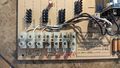 Terminal closeup. Do note that normally the primary side of the transformer with the fuse goes on the far right two.

Transformer:[27]
- Input: Configurable 115 or 230v AC
- Output: Rated at 12.6v DC (Unloaded is higher)
- Max Current: 1.5A
- Max VA: 18.9
-
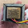 Transformer Primary
 -
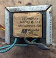 Transformer Secondary


Marked as "F-325X Filament Transformer" on the primary, "MagneTek Triad" on the secondary. Seems to suggest prior life in tube equipment but amazingly it's still made, just modernized. If you want, you can even buy a new one on Mouser for ~$15
Primaries are in series for 230v, parallel for 115v. More info on configuring in the (LCRx) transformer wiring section below.
Photos
-
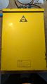 Front with door closed
 -
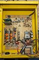 Door open showing mainboard
 -
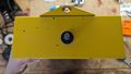 Top of the enclosure, showing the antenna mount
 -
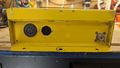 Bottom of the enclosure, showing conduit and vent holes as well as an unused SO-239 connector to replace the whip antenna.
 -
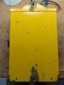 Back of the enclosure, showing the integrated mounting holes.
 -
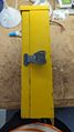 Side of the enclosure with latch. First flips out, then rotate the wing to loosen the clamp.
 -
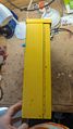 Side of the enclosure with the hinge. The hinge cannot be removed from the door, but the door and hinge can be removed from the enclosure with three screws and nuts.
 -
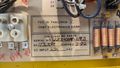 Info written near the bottom center of the mainboard. Shows FCC-ID, serial, receive frequency, input voltage, and ship date.
 -
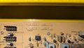 Configured tone information handwritten on the CD&F main board near the top center. Sequence 1 is to activate, sequence 2 is to deactivate.
 -
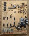 Bare mainboard of the CD&F. All cards removed for visibility.
 -
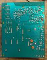 Back of the CD&F mainboard. There is conformal coating on the back which makes it difficult to probe things. It can be removed with acetone or MEK.
 -
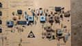 Closeup of the double conversion super heterodyne radio receiver circuitry in the CD&F.
 -
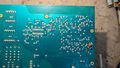 Closeup of the rear of the double conversion super heterodyne radio receiver circuitry in the CD&F. Mirrored to match Cdf_rx_closeup.jpg.


(LCRx) Transformer wiring
The F-325X "filament" transformer used to power the entire board can be reconfigured for 115 or 230v primary voltage and is detailed on the windings themselves. The secondary should be on a 3 pin molex style connector with both wires green. The output of the transformer should be around 12v AC, but as with any unregulated supply it will be a bit higher than expected.
- 115v Operation: Tie together the black and red/black striped wire together and tie the yellow/black striped wire and the green/black striped wire together. You now have two pairs of wires for live and neutral.
- 230v Operation: Tie the yellow/black striped and red/black striped wires together and insulate them properly. You can now attach live and neutral to the black and black/green striped wire.
I suggest you confirm winding integrity with a multimeter and/or use a dim bulb tester to prevent any catastrophies from happening.
Architecture & Operation
This is going in order from control signal thru processing, all the way to output contact closure.
RF comes in via 3 pin antenna connector (top right) and goes thru double conversion superhet, then into MC3357P IF.
Demod audio comes out from pin 9 of the MC3357P and goes into the commoned P1 pins of the 4 decoder board sockets.
Tone filters A1 and A2 take input on P1, VCC on P2, GND on P3, and P4 is the logic NOT output of the XR2211A IC on the tone filter PCB. This output is normally high, and gets pulled low when the input signal on P1 falls within the set passband. Both filters are in parallel on the input, VCC, and GND, but the outputs of all four sockets are separate and go to the decoder boards. The decoder boards are composed of logic gates and supporting circuitry to detect the order of pulses from the tone filters and perform the appropriate action in cooperation with the timer board. When the signal to start the timer is decoded, the LED on the first decoder board blinks breifly, then the timer board signals the relay driver to engage the relay. The indicator lights on the timer board and the relay driver also illuminate. On my unit, the unit times out after approximately 3 minutes of being activated if no stop signal is received on the radio or locally via contact closure.
Receiver Circuit
The receiver on board the F49LCR-2 is a double conversion superheterodyne circuit. RF comes in via the 3 pin header (only 2 used) and immediately goes into what I presume is a preamplifier with a MPS5179 RF transistor[28].
The Local Oscillator (LO) crystal on by unit is marked "154.240" on top of the can, and "47.180" on the side. After messing with some math, I discovered the LO gets tripled (presumably by some magic with the other transistors and passives nearby) to 141.54 MHz.
The incoming RF is then mixed and subtracted with the tripled LO signal to get the 10.7 MHz intermediate frequency (IF). You can calculate different LO crystal frequencies or input frequencies with the following equation, assuming you have one or the other:
10.7 = rxFreq - (crystFreq * 3)
The downstream Motorola MC3357P[29] IC takes the standard 10.7 MHz IF input and converts it down again to 455 kHz and does some filtering, then using its internal quadrature FM detector demodulates the audio into a 200-350mV RMS audio signal on pin 9 of the IC.
There is some more audio filtering that pin 9 feeds into, but afterwards the cleaned up audio goes right into the tone filter boards on a common trace.
As for the LCR-1 variant, based on the FCC-ID data it seems that the receiver will be nearly identical, though the resulting IF mixer will most likely be an addition rather than subtraction circuit due to the lower operation frequency.
Retuning for the 2 Meter Amateur Radio Band
Original Plan
My original plan was to source some kind of crystal between 44.43 to 45.7 MHz which corresponds to 146 to 147.975 MHz when plugged into the above equation. Upper limit of 147.975 chosen assuming a transmitted signal of 25kHz NFM. After doing some more reasearch though, I discovered the Si5351 and it's breakout board from Adafruit which is a programmable clock generator that can output 3 separate clock signals from 8 kHz to 160 MHz. What a useful chip! This has the advantage of costing about the same as a vintage hard to find crystal of a specific frequency while also being able to be reprogrammed easily via I2C. The only downside is that the chip has no ROM so any configuration is lost upon power down. Despite this, that IC combined with a low power I2C enabled microcontroller attached to a suitable source of power from the board should yeild a highly versatile replacement to the old crystal.
Si5351 Breakout
I ordered the board and when it arrived, I attached it to an arduino nano with 5v, GND, SCL and SDA (A4 and A5 on the nano). After programming the board and checking it with my new DSO, it showed 45.55 MHz as programmed using the aforementioned arduino and the Etherkit Si5351 example sketch. I removed the crystal from the LO circuit and attached the Si5351 CLK0 to the collector of Q4 as is done with the original crystal and also grounded the breakout board to the other crystal pad. Initial tests show nearly identical functionality from stock, even without tuning any filter components onboard. The receiver now responds to signals on 147.350 MHz, comfortably near the top of the 2 meter band. With that, I taped the arduino and breakout board together, insulated, and hijacked power from the main LM7812 regulator to power it.
-
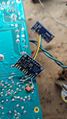 Testing the breakout board with temporary connections.
 -
 Final mod. The arduino and breakout taped together and insulated, using the original crystal through holes and taking power from the main L7812 regulator.
 -
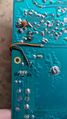 Connections for Vin and GND on the arduino going to the main 12v regulated supply.


SCx (Multi-Option Large Silver/Yellow/Red Unit)
The second type of unit I have acquired (an SC2), is much larger and more complex. It can support up to 3 (technically 4) function timers, 4 decoders, and six tone filters. This allows for a much more complex operation.
The manual specifies a number of optional add-ons:
- D1 - Thermostat controlled heater (mounts below the receiver board)
- D2 - CTCSS decoder board (mostly obsolete, rare)
- D3 - Top deck mount VHF low antenna
- D4 - Top deck mount VHF high antenna
- D5 - Additional heavy duty 10A relay (relay #2)
- D6 - Cabinet painted red
- D7 - Additional intermodulation filter (not sure what this is?)
- D8 - Audio kit (for servicing decoders)
- D9 - Test transmitter encoder (possibly one of the FCC-IDs? Maybe CDF1 and CDF2.)
- D10 - Additional tone filter
Specifications
Physical
SC Series:
- Height: 325mm (12.75") & 387mm (15.25") from bracket top and bottom
- Width: 320mm (12.59") top section & 288mm (11.33") bottom section
- Depth: 95mm (3.74") top section & 90mm (3.54") bottom section
- Antenna length (installed): 470mm (18.5")
- Weight: Approx. ?? lbs
Transformer:[30]
- Input: Configurable 115 or 230v AC
- Output: Rated at 24v DC OR 12v DC depending on config (Unloaded is higher)
- Max Current: 1A/2A (24/12v)
- Max VA: 24
-
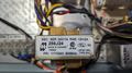 Transformer details

More info on configuring in the SC transformer wiring section below.
Photos
-
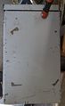 Front case before restoration
 -
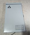 Front case of my unit after restoration
 -
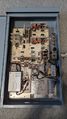 Inside my restored unit with missing activation buttons added
 -
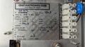 Nameplate with details
 -
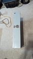 Latch side of my restored unit
 -
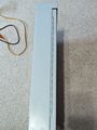 Hinge side of my restored unit
 -
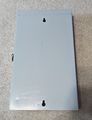 Back of my restored unit
 -
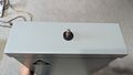 Top of my restored unit showing the antenna bulkhead
 -
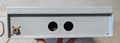 Bottom of the restored unit showing optional SO-239 connector


(SC) Transformer wiring
The main transformer in the unit is a 266J24 from Hammond Manufacturing.
- 115v Operation: Tie black/brown together and white/orange together.
- 230v Operation: Tie white/brown together and insulate. Input power on black and orange.
The main board operates on 12v, so just make sure that the red/grey and yellow/blue wires are tied together in those pairs for 12v operation.
-
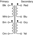 Transformer pinout from Hammond
 -
Transformer details

Tone Filter Test Board
The tone filter test board is pretty self explanatory. It contains six LEDs, one for each tone filter, which are connected to a MC14069BCP[31] hex inverter IC.
When the a tone filter detects a signal within its configured bandwidth and pulls it's P1-4 pin low, the hex inverter IC inverts that signal, pulling the corresponding LED high which illuminates it, indicating the filter is active.
|
|
-
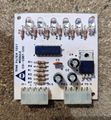 Front of the SC series tone filter test board
 -
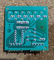 Rear of the SC series tone filter test board


Programming board
The programming board is the center of the unit's operation. It's a bare board that allows for jumpers to be placed to route signals from the tone filters to the decoders. The manual details the configuration in more detail, but here's the basics.
There are letter and number combinations printed on the programming board, which correspond to each function and it's inputs.
- V - CD Steady (Alert)
- W - CD Cycle (Attack)
- X - Fire
- Y - Cancel
The numbers corresponding to the letters (eg. Y1) is which order the filter signal should be sent in to trigger the function. 1 is the first signal, 2 is the second signal. Theoretically, this allows for any combination of common or separate tones to be configured to activate any function as desired, though there may be limitations that I am not aware of.
|
|
|
-
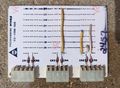 Front of the SC series programming board
 -
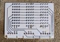 Rear of the SC series programming board


Power Supply Module
On the LCx series, the power supply section is built into the main board. It is similar in architecture to the SC series, though the latter has it on a removable module. The power supply module takes in the unregulated AC output of the transformer, rectifies it, tames it down to 12v via a 7812 voltage regulator, and finally filters the DC with inductors and capacitors.
|
|
-
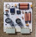 Front of the SC series programming board
 -
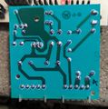 Rear of the SC series programming board


DTMF Tone Decoders
I recently became aware that at some point, CD&F made DTMF decoders that use the two tone decoder PCB and have a Norcomm NC401 module attached to them. The manual for the module can be viewed here. Its based on an 8051 mcu and the classic MT8870 DTMF decoder IC. You can program various functionality and digit sequences into it.
-
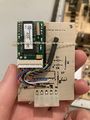 An example of a DTMF decoder card

Other Units
There are more unit types out there which include more variants of the LCR and SCx line:
Smaller Units:
- LCR1 - (most likely) VHF Low band small yellow unit
- LCR2 - VHF High band small yellow unit
Larger Units:
- SC1 - VHF Low band large silver/yellow unit
- SC2 - VHF High band large silver/yellow unit
- SC3 - UHF band large silver/yellow unit
General Notes/Things to Watch Out For
- On the back of the main board and parts of the tone filters there is a conformal coating. I suggest removing it before reflowing joints to prevent contamination of the solder. Acetone or M.E.K. seems to do well along with mechanical removal. Be careful with your application of force, you can very easily strip off the solder mask! Ask me how I know!
- These devices are quite old, and excessive handling and stress seems to not play nice to the solder joints. I have fixed both the tone filters and receiver section by reflowing every joint with leaded solder.
- Due to the XR2211A IC being obsolete and quite hard to source nowadays, I may try to design my own tone decoder board using the LM567 IC which is still available in SMD form factors. The LM567 also outputs a logic low when signal is detected, but the design will have to incorperate a LDO 5v regulator to power the chip from the 12v the cards get.
- Similarly, many of the ICs are obsolete nowadays, though some have replacements. The main Maxin timer IC is absurdly expensive per chip, so I may redesign the entire thing.
- I have not adjusted any of the filter components on the receiver circuit yet, but I did run an experiment by leaving the device plugged in with the antenna attached inside my house while sending the activation signal from a few dense suburban blocks away. The board operated perfectly with 5W from my Anytone 878, turning on and off.
- While the tone filters are labled J1 thru J6 on the PCB, the actual numbering is reversed, tone filter 1 is at the top and 6 is at the bottom. Despite that, my unit (and I suspect others that were reconfigured by a third party) may not start at slot 1. My unit has slots 6, 5, and 4 occupied with the corresponding wiring on the programming board. The nameplate implies slots 1, 2, and 3 however. Overall it doesn't really matter if things aren't in numerical order, but it sure as hell makes things confusing...
- On the maxon data radio DB-15 connector, you can solder a normal speaker to pin 9 and GND (4) to monitor the recieve audio. You can adjust volume with RV401 onboard inside the radio, or just use an inline resistor if you are lazy.
- ↑ https://www.fedsig.com/product/fc-siren-controller
- ↑ https://fccid.io/F49
- ↑ https://fccid.io/F49LCR-2
- ↑ https://fccid.io/F49LCR-1
- ↑ https://fccid.io/F49EMR-3
- ↑ https://fccid.io/F49EMR-2
- ↑ https://fccid.io/F49EMR-1
- ↑ https://fccid.io/F49CDF-2
- ↑ https://fccid.io/F49CDF-1
- ↑ https://fccid.io/F498POCDF-2
- ↑ https://fccid.io/F498POCDF-2
- ↑ https://fccid.io/F498POCDF-1
- ↑ https://assets.maxlinear.com/web/documents/xr2211av104.pdf
- ↑ https://www.mouser.com/datasheet/2/308/1/MC14069UB_D-2315482.pdf
- ↑ https://www.ti.com/lit/ds/symlink/cd4069ub.pdf
- ↑ https://www.mouser.com/datasheet/2/308/1/mc14049b_d-1193035.pdf
- ↑ https://www.ti.com/lit/ds/symlink/cd4050b.pdf
- ↑ https://www.mouser.com/datasheet/2/308/1/MC14001B_D-2315187.pdf
- ↑ https://www.ti.com/lit/ds/symlink/cd4073b.pdf
- ↑ https://www.onsemi.com/pdf/datasheet/mc1455-d.pdf
- ↑ https://www.mouser.com/datasheet/2/308/1/MC14001B_D-2315187.pdf
- ↑ https://www.ti.com/lit/ds/symlink/cd4073b.pdf
- ↑ https://www.mouser.com/datasheet/2/308/1/MC14001B_D-2315187.pdf
- ↑ https://www.ti.com/lit/ds/symlink/cd4011b.pdf
- ↑ https://www.onsemi.com/pdf/datasheet/mc1455-d.pdf
- ↑ https://www.analog.com/media/jp/technical-documentation/data-sheets/1360.pdf
- ↑ https://www.mouser.com/datasheet/2/410/F_325X-1892699.pdf
- ↑ https://www.mouser.com/datasheet/2/149/mps5179-493155.pdf
- ↑ https://www.discriminator.nl/ic/mc3357.pdf
- ↑ https://www.hammfg.com/electronics/transformers/power/266.pdf
- ↑ https://www.mouser.com/datasheet/2/308/1/MC14069UB_D-2315482.pdf