GE Medical Flashpad Digital Xray Detector: Difference between revisions
Gamerpaddy (talk | contribs) |
Gamerpaddy (talk | contribs) m added github page |
||
| Line 12: | Line 12: | ||
All files used are found on the official Optima XR220amx Application Software and Linux OS DVD 5406106-10 Rev3. | All files used are found on the official Optima XR220amx Application Software and Linux OS DVD 5406106-10 Rev3. | ||
<br /> | <br /> | ||
Project files can all be found on the Github page: https://github.com/gamerpaddy/GE-Flashpad-Python-Controller/blob/main/README.md | |||
[[File:Flashpad xray 20261001 first capture.png|thumb|First image captured in this months long project.]] | [[File:Flashpad xray 20261001 first capture.png|thumb|First image captured in this months long project.]] | ||
==Purpose and Motivation== | ==Purpose and Motivation== | ||
Revision as of 13:20, 2 October 2026
Overview
The GE Flashpad is a Digital Radiography image sensor from approximately 2010, originally used in the GE Optima 220AMX mobile X-ray unit. It was designed to replace analog film in radiology, dramatically reducing image acquisition time from hours to seconds.

Due to its high original cost and specialized application, used units occasionally appear on professional B2B marketplaces in the $15,000–$50,000 range. On eBay, prices typically fall between $1,500 and $5,000, though units at this price point are often in poor condition and may fail the built-in self-test or not function at all.
All files used are found on the official Optima XR220amx Application Software and Linux OS DVD 5406106-10 Rev3.
Project files can all be found on the Github page: https://github.com/gamerpaddy/GE-Flashpad-Python-Controller/blob/main/README.md

Purpose and Motivation
This project documents the reverse engineering of the GE FlashPad wireless digital radiography detector used with the Optima XR200/220 AMX mobile X-ray system, with the goal of freeing these detectors for independent use.

Large numbers of these detectors reach the used market, but each one is bound to its original Optima 220 AMX console. Once separated from that console, or once the console is decommissioned, the detector is effectively useless even though the hardware is fully functional. There is a Windows software but it is not obtainable. The aim of this work is to remove that artificial barrier so that a standalone FlashPad can be paired, configured, and read out by any host, without the half million dollar console it was sold with.
The intended beneficiaries are:
- Hobbyists, researchers, and engineers who want a high quality flat panel detector for their own imaging projects. for example studying the fluid movement in plants. https://www.youtube.com/watch?v=j-FHbHoiwNk (Xray timelapse by Ben Krasnow / Applied Science using a GE Flashpad)
- Veterinary practices, which can put surplus human grade detectors to good use at a fraction of the cost of new equipment.
- Clinics and hospitals in countries and regions where a complete commercial system is unaffordable, allowing detectors to keep providing diagnostic imaging instead of being scrapped.
All files, findings, protocol documentation, and tools produced by this project are public and open source, so that anyone can study, reproduce, and build on the work.
Technical Specifications


The Flashpad uses a ~40 × 40 cm CsI scintillator bonded to a TFT photodetector array mounted on glass. The assembly is highly sensitive to shock and impact damage. See section drop and shock event log
| Parameter | Value |
|---|---|
| Resolution | 2048 × 2048 px |
| Bit depth | 16-bit per pixel |
| Frame size | 8 MiB (8,388,608 bytes) |
| Spatial resolution | Up to 5 lp/mm (theoretical) |
| Scintillator material | Caesium iodide (CsI) |
| Detector type | TFT photodetector array (glass substrate) |
| Panel size | ~40 × 40 cm |
| Pixel pitch | 0.2 mm |
| Active area | (12, 12) to (2035, 2035) |
| Exposure detection | None — the panel is armed and waits (not AED) |
The theoretical 5 lp/mm spatial resolution is primarily limited in practice by the focal spot size of the X-ray source. Use of an anti-scatter grid can improve effective resolution.
Hardware Features
Shock logging
The unit contains an internal accelerometer that logs significant shock events — but only when a battery is inserted. As there is no backup battery, shock events occurring while unpowered are not recorded.
Wireless connectivity
Some units include a UWB transmitter for Wireless USB; others may be equipped with a Wi-Fi module instead. UWB is not required - the detector boots with Ethernet selected as its active link if the port pins are bridged, and image transfer over the tether works fully.
Ethernet interface
There is a 100 MBit Ethernet interface through the tether cable which can be tapped and used for communication. Exposed metal contacts on the bottom connector are isolated via relays by default. Enabling Gigabit Ethernet connectivity requires shorting or driving two specific pins. This has not been investigated further at this time.
The firmware selects one of three internal "nets" based on a power-state byte reported by the power MCU:
| Power state | Net | Accepted link speed |
|---|---|---|
| 2, 3 | 1 | 10 or 100 Mbit |
| 1, 5, 8 | 2 | 100 or 1000 Mbit |
| 6, 7 | 0 | UWB / wireless |
The negotiated PHY speed must match the selected net. If it does not, the firmware sets its active-link byte to 0xFF and silently discards all image frames — while control traffic keeps working normally, which makes this failure mode look like "the detector refuses to send images". 100 Mbit full duplex satisfies both Ethernet nets and is what GE's own console script configures. The unit tested here reports power state 3 (net 1).
Host Requirements
Three host-side settings are mandatory. Getting any of them wrong produces a working control channel with no image data.
| Setting | Value | Why |
|---|---|---|
| Host IP | 192.168.1.1/24 |
The detector replies to a stored destination address, not to the sender. From any other address you get no replies at all. |
| Link speed | 100 Mbit, full duplex, autoneg off | Must match the detector's selected net (see above). |
| Interface MTU | ≥ 5000 | Image datagrams are 4104 bytes. At the default MTU of 1500 every frame is dropped by the NIC before it reaches the socket. |
These are exactly the values GE's own console applies in
/magichome/xruser/bin/configureNetworkForDetector.sh:
echo "MTU=5000" >> ifcfg-eth0
echo 'ETHTOOL_OPTS="speed 100 duplex full autoneg off"' >> ifcfg-eth0
IPADDR=192.168.1.1
A dedicated network interface is strongly recommended, since forcing 100 Mbit and a 5000-byte MTU on a shared adapter affects everything else on it.
Linux:
ip addr add 192.168.1.1/24 dev eth0
ip link set eth0 mtu 5000
ethtool -s eth0 speed 100 duplex full autoneg off
Windows: set the adapter's Speed & Duplex to 100 Mbps Full Duplex and Jumbo Frame to 5000 or larger in the adapter's advanced properties (needs administrator rights). Also note that an interface Windows classifies as a Public network blocks unsolicited inbound UDP; either mark it Private or send from the same port you expect the reply on.
Communication Protocol
This section documents the URP/PDAP protocol used by the GE Flashpad (codename Apollo (Or FeiTian, Mammo, Gryphon etc.) to communicate with a host over Ethernet. All findings are based on live capture tests, configuration files, and reverse-engineering of the GE SuperBee software stack.
Network Setup
Default detector IP is 192.168.1.30. The host must be 192.168.1.1
(see Host Requirements).
| Role | IP | Port | Direction |
|---|---|---|---|
| All commands: host -> detector | 192.168.1.30 | 8100 (UDP) | Host sends here |
| Replies before PORT_SETUP: detector -> host | - | 48879 (0xBEEF, UDP) | Detector's default reply port |
| Discovery beacons: detector -> host | - | 4500 (UDP) | Detector sends here initially |
| Protocol replies: detector -> host | - | 5550 (UDP) | Detector sends here after PORT_SETUP |
| Image pixel data: detector -> host | - | 6660 (UDP) | Detector streams frames here |
48879 (0xBEEF) is the detector's genuine default reply port, not an artifact of early test scripts. It is a hard-coded constant in the firmware, and before any PORT_SETUP the detector sends every reply there. After PORT_SETUP it uses the configured command port instead (5550 by default), so a probe pinned to 48879 goes silent once an acquisition handshake has run.
Protocol Layers
Two layers, carried over UDP:
- URP (Unified Registration Protocol)
- 8-byte wrapper on every packet. Handles sequencing and acknowledgement.
- PDAP (Proprietary Detector Access Protocol)
- The actual command layer, present inside URP packets when
CmdFlag = 0.
Every UDP packet starts with a URP header:
[SeqId : 4 bytes LE] [CmdFlag : 4 bytes LE]
CmdFlag = 0-- data packet, PDAP command follows.CmdFlag = 1-- bare ACK, no PDAP body. SeqId echoes the packet being acknowledged.
Both sides must ACK every data packet immediately. The detector silently drops packets with a SeqId it has already seen, so always increment SeqId for each new command.
When CmdFlag is 0, the PDAP header follows immediately:
[cmd_type : 4 bytes LE] [payload_len : 4 bytes LE] [payload ...]
Replies arrive as one bare ACK followed by the data reply, which is normally repeated three times. Deduplicate on SeqId.
Connecting to the Detector
The connection sequence is:
- Broadcast
SYSTEM_STARTUPto tell the detector where to reply. - The detector sends a
BEACONback -- ACK it and sync your sequence counter. - Send
PORT_SETUPto configure the reply and image ports. - Send
SIGNATURE_REQUESTto read the detector identity (serial number, model, firmware, MAC).
Step 1: SYSTEM_STARTUP
Broadcast UDP to 192.168.1.255:8100. Always uses SeqId = 0.
URP : [00 00 00 00]  SeqId = 0
      [00 00 00 00]  CmdFlag = 0
PDAP: [01 00 00 00]  cmd_type = 1
      [06 00 00 00]  payload_len = 6
      [15 AE]        host reply port = 5550 (big-endian)
      [C0 A8 01 01]  host IP = 192.168.1.1 (network byte order)
import socket, struct

sock = socket.socket(socket.AF_INET, socket.SOCK_DGRAM)
sock.setsockopt(socket.SOL_SOCKET, socket.SO_BROADCAST, 1)
sock.bind(("0.0.0.0", 5550))

HOST_IP   = "192.168.1.1"
DET_IP    = "192.168.1.30"
HOST_PORT = 5550
IMG_PORT  = 6660

def make_urp_packet(seq_id, pdap_bytes):
    return struct.pack("<II", seq_id, 0) + pdap_bytes

pdap = struct.pack("<II", 1, 6) + struct.pack(">H", HOST_PORT) + socket.inet_aton(HOST_IP)
sock.sendto(make_urp_packet(0, pdap), ("192.168.1.255", 8100))
Step 2: Receiving the BEACON and ACKing
The detector broadcasts a BEACON (cmd_type=1) roughly every 2 seconds. After sending SYSTEM_STARTUP you should get one quickly. Parse the detector SeqId from the URP header and ACK it:
data, addr = sock.recvfrom(4096)
det_seq = struct.unpack_from("<I", data, 0)[0]

# send bare ACK
ack = struct.pack("<II", det_seq, 1)
sock.sendto(ack, (DET_IP, 8100))

# all subsequent commands start from here
host_seq = det_seq + 1
Step 3: PORT_SETUP
Tells the detector which host ports to use for replies and image data. Port fields are big-endian — this is confirmed correct in practice.
PDAP: [02 00 00 00]  cmd_type = 2
      [04 00 00 00]  payload_len = 4
      [15 AE]        host cmd port = 5550 (big-endian)
      [1A 04]        host image port = 6660 (big-endian)
pdap = struct.pack("<II", 2, 4) + struct.pack(">HH", HOST_PORT, IMG_PORT)
sock.sendto(make_urp_packet(host_seq, pdap), (DET_IP, 8100))
host_seq += 1
# expect bare ACK from detector
PORT_SETUP must be sent before SIGNATURE_REQUEST, otherwise the signature reply goes to the previously configured port and the step appears to time out.
Step 4: Reading the Serial Number (SIGNATURE_REQUEST)
Empty command, the detector replies with a 54-byte payload containing its identity.
pdap = struct.pack("<II", 3, 0)   # cmd_type=3, payload_len=0
sock.sendto(make_urp_packet(host_seq, pdap), (DET_IP, 8100))
host_seq += 1

# reply is 70 bytes total: 8 URP + 8 PDAP header + 54 payload
data, _ = sock.recvfrom(4096)
payload = data[16:]   # skip URP (8) + PDAP header (8)

mac      = payload[0:6]
serial   = payload[22:34].rstrip(b'\x00 ').decode()
model    = payload[34:46].rstrip(b'\x00 ').decode()
fw_bytes = payload[46:54]
firmware = ".".join(str(b) for b in fw_bytes)

print(f"MAC:      {':'.join(f'{b:02X}' for b in mac)}")
print(f"Serial:   {serial}")
print(f"Model:    {model}")
print(f"Firmware: {firmware}")
Expected output:
MAC:      40:F4:A0:00:78:4D
Serial:   UA45829-7
Model:    5340000-7
Firmware: 1.6.0.4.2.0.1.3
Exposure Model
The FlashPad is not an AED (automatic exposure detection) panel. It does not sense radiation to start integrating. It must be armed by command, and the X-ray must fire inside the armed window. The host owns the timing.
Evidence: there is no AED-related parameter anywhere in the detector configuration files;
the host software carries an explicit ExposureTrigger subsystem
(startExposureTrigger / stopExposureTrigger on a dedicated
trigger actor); the AcqSync actor is an interlocked state machine driven by
the operator's exposure switch (AS_EXPOSE_ON / AS_EXPOSE_OFF,
states WAIT_FOR_EXPOSE / WAIT_FOR_STOP_EXPOSE, and the log
string "Timeout wait for exp trigger done or expose off from user"); and the detector's
own acquisition primitive takes a MaxExpose Time, i.e. a timeout, not a threshold.
Sequence:
- Arm: download the acquisition script and EXECUTE (two-phase, see below).
- The panel runs
numScrubs × scrubDurationof scrubbing first — a delay before the window opens. - The integration window opens for
MaxExpose Time. - The X-ray must fire during that window.
tailTime, readout, then the image is registered and can be pulled.
If the window expires with no exposure the acquisition still completes normally and still returns a full frame — it is simply an unexposed one. That makes it easy to test the whole chain without a generator.
Timing units
All script times are in ticks of an internal clock measured at roughly 26 MHz
(a MaxExpose Time of 250,000,000 produced a measured ~9.5 s window).
| Value (ticks) | Approx. time | Note |
|---|---|---|
| 400,000 | ~15 ms | GE's own Script 0 / Script 1 setting, for a hardware-synchronised generator |
| 4,000,000 | ~150 ms | A practical compromise |
| 250,000,000 | ~9.5 s | Very forgiving, for software or manual triggering |
A longer window integrates more dark current, which raises the baseline and the noise, so use the shortest window your trigger timing can reliably hit. A dark frame is only valid for the window length it was taken at.
Running an Acquisition
Two-phase EXECUTE is mandatory
The host must issue two separate EXECUTE_SCRIPT commands:
- Download Script 7 (ROE init) and EXECUTE it. Wait for its EXECUTION_COMPLETE. Script 7 ends by sending host event 17, and the detector needs that to be processed before an acquisition script may run.
- Then download Script 0 (or Script 1) and EXECUTE that.
Observed status bytes in the EXECUTE_SCRIPT reply:
| Status | Meaning |
|---|---|
| 0xC4 / 0xC7 / 0xC9 / 0xCA | Normal, script running, EXECUTION_COMPLETE will follow |
| 0xE3 | Sequence incomplete — the ROE init phase did not run separately first |
Image retrieval: cmd 0x41 then cmd 0x98
Image data is not pushed automatically. After the acquisition completes the host must ask for it, in this order:
| cmd_type | Name | Request payload | Reply payload |
|---|---|---|---|
| 0x41 | IMAGE_RETRIVAL_REQUEST | [scriptId:4 LE] | [length:4 LE][imageId:4 LE] × N |
| 0x98 | IMAGE_RETRIVAL | [imagePort:2 LE][hostPort:2 LE] | [status:4 LE] — 0 = ok, 1 = no such image |
0x41 must be sent first. It makes the detector enumerate the images it is holding into an internal list, and 0x98 acts on the first entry of that list. Sent on its own, 0x98 always fails with status 1.
The first word of the 0x41 reply is a length field, equal to
count × 4 + 4 — not an image count. This is a common misreading:
payload_len = 4, payload04 00 00 00→ zero images held.payload_len = 8, payload08 00 00 00 00 00 01 00→ one image, imageId 0x00010000.
A successful 0x98 reply is 00 00 00 00, and the detector begins streaming
immediately.
Sequence Overview
HOST                                     DETECTOR
 |                                           |
 |-- SYSTEM_STARTUP (broadcast) ----------->|
 |<- BEACON (cmd_type=1) --------------------|
 |-- bare ACK ------------------------------>|
 |-- PORT_SETUP (cmd_type=2) -------------->|
 |-- SIGNATURE_REQUEST (cmd_type=3) ------->|
 |<- SIGNATURE_REPLY (54 bytes) -------------|
 |                                           |
 |-- GENERIC_SCRIPT Script7 (ROE init) ---->|   phase 1
 |-- EXECUTE_SCRIPT (cmd_type=6) ---------->|
 |<- EXECUTE_SCRIPT_REPLY (status 0xC4) -----|
 |<- DETECTOR_STATE_NOTIFY  state_id=17 -----|
 |<- EXECUTION_COMPLETE (0x10000) -----------|
 |                                           |
 |-- GENERIC_SCRIPT Script0 (acquisition) ->|   phase 2
 |-- EXECUTE_SCRIPT (cmd_type=6) ---------->|
 |        [ X-RAY FIRES INSIDE THE WINDOW ]  |
 |<- EXECUTION_COMPLETE (0x10000) -----------|
 |                                           |
 |<- IMAGE_XFER_STATUS_QUERY (0x30000) ------|   received=0
 |-- IMAGE_XFER_STATUS_REPLY (cmd_type=9) ->|
 |-- IMAGE_RETRIVAL_REQUEST (0x41) -------->|
 |<- 0x41 reply: length + imageId -----------|
 |-- IMAGE_RETRIVAL (0x98) ---------------->|
 |<- 0x98 reply: status 0 -------------------|
 |<- 2048 × 4104-byte image datagrams -------|   to port 6660
 |<- IMAGE_XFER_STATUS_QUERY (0x30000) ------|   received=2048
 |-- IMAGE_XFER_STATUS_REPLY (cmd_type=9) ->|   numMissed=0
The IMAGE_XFER_STATUS_QUERY (0x30000) exchange is a retransmission mechanism:
the detector reports how many buffers it believes arrived, and the host answers with
cmd_type 9 listing any missing buffer indices.
Sequence Counter Rules
SYSTEM_STARTUPalways usesSeqId = 0.- After the first beacon, set host SeqId to beacon_SeqId + 1.
- Increment SeqId by 1 for every new data packet (CmdFlag=0).
- Bare ACKs echo the SeqId of the packet being acknowledged and do not consume a SeqId.
- The detector silently drops any packet with a SeqId it has already processed, so never reuse one.
Image Transfer
Frame format
The image arrives as 2048 UDP datagrams of 4104 bytes on port 6660, sent from the detector's port 8100:
[imageId : 4 bytes LE] [blockIndex : 4 bytes LE] [4096 bytes of pixel data]
2048 × 4096 = 8,388,608 bytes = 2048 × 2048 × 16-bit. Pixel data is little-endian
unsigned 16-bit. blockIndex is 1-based in practice; always reassemble by
index rather than arrival order.
The 4104-byte payload means the Ethernet frame is about 4150 bytes, far above the standard 1500-byte MTU — hence the MTU 5000 requirement. The firmware builds a 50-byte header (2-byte MAC alignment pad + Ethernet 14 + IP 20 + UDP 8 = 44, then imageId at offset 44 and blockIndex at 48), which is why exactly 8 bytes remain visible in the UDP payload.
A quirk worth handling: the first datagram often arrives 16 bytes short and without its
header. Detect it with len(data) % 4104 and treat those bytes as block 0's
payload.
Reassembly
import struct, numpy as np

STRIDE, PAYLOAD, NBLOCKS, DIM = 4104, 4096, 2048, 2048

def reassemble(raw):
    blocks, off = {}, 0
    head = len(raw) % STRIDE          # short, header-less first record
    if head:
        blocks[0] = raw[:head].ljust(PAYLOAD, b"\x00")
        off = head
    while off + 8 <= len(raw):
        image_id, index = struct.unpack_from("<II", raw, off)
        blocks.setdefault(index, raw[off + 8: off + STRIDE].ljust(PAYLOAD, b"\x00"))
        off += STRIDE
    buf = b"".join(blocks.get(i, b"\x00" * PAYLOAD) for i in range(NBLOCKS))
    return np.frombuffer(buf, dtype="<u2").reshape(DIM, DIM)
Image Correction
Offset (dark) correction
A dark frame is an exposure-free readout: the panel's fixed offset plus the dark current accumulated over the window. Capture one with the same settings but no X-ray, then subtract it. This removes the pedestal and most fixed-pattern noise.
A dark frame is only valid for the window length it was taken at, because dark current scales with integration time. Re-shoot it whenever you change the window.
Representative values from the unit tested, with a ~9.5 s window:
| Frame | Mean (ADU) |
|---|---|
| Dark / unexposed | ~1835 |
| 100 ms exposure | ~3261 |
| Difference (signal) | ~1425 |
Dead rows and columns
The panel has defective lines that appear as dark lines across the image. On the unit tested these are row 48, row 1093 and column 783 — each exactly one pixel wide and fully dead (median 0–3 ADU against neighbours at 560–1900).
A workable detection method: take the median of each row and column, compare it to the median of its local neighbourhood (±16 lines), and normalise by the MAD. Genuine dead lines score 150–320 while ordinary image structure stays below about 21, so a threshold around 25 separates them cleanly. Exclude the outer ~12 rows and columns, which always read oddly. Repair by linear interpolation between the nearest good lines.
Single-pixel repair is correct here — there is no measurable charge-sharing into the neighbouring lines. Do not run an isolated-hot-pixel pass before the line repair: its neighbour averages are taken from an image that still contains the dead lines, so pixels beside them get flagged and then "repaired" by averaging the dead line's zeros back in, which smears the lines wider instead of removing them.
For quantitative work the calibration maps stored in the detector (upload IDs 0x10, 0x11, 0x12) provide proper gain and offset data per dose level.
Script Download
The detector does not have fixed acquisition commands. Instead the host downloads small programs, called scripts, that the detector stores by ID and then runs on command. A script is a sequence of primitive operations: program the ROE (readout electronics) registers, wait, acquire an image, signal an event. The acquisition behavior of the panel is defined entirely by these downloaded scripts, which are taken from the application mode XML files (for example IDC_URP_SE_2200.xml for single energy, 2048 by 2048).
The GENERIC_SCRIPT command
A script is sent to the detector with the GENERIC_SCRIPT command, cmd_type 5. The wire format is:
[cmd_type   : 4 LE]   = 5
[length     : 4 LE]   = 8 + sum(command sizes) + 2
[script header : 8 bytes]
[packed command 1]
[packed command 2]
...
[terminator : 2 bytes] = 00 00
The 8 byte script header is:
| Offset | Size | Field | Meaning |
|---|---|---|---|
| 0 | 2 LE | scriptID | the slot the script is stored in |
| 2 | 2 LE | repeatCount | 0 = run once, 65535 = loop forever |
| 4 | 4 LE | repeatEvent | event ID that breaks an infinite loop (0 if unused) |
Note: the application mode XML lists a fourth header value, ROEdata. This is a substitution source for the script's commands, not a field on the wire. The wire header is exactly 8 bytes.
Packed command primitives
Each command inside the script starts with a one byte DETECTORCODE that selects its type and length:
| DETECTORCODE | Command | Size | Layout (after the code byte) |
|---|---|---|---|
| 1 | Acquisition | 17 | typeMode:1, imageId:1, noScrubs:1, scrubDuration:4 LE, maxExposeTime:4 LE, tailTime:4 LE, transferMode:1 |
| 2 | ROE command | 14 | responseFlag:1, timerValue:4 LE, roeCmd:4 LE, roeData:4 LE |
| 3 | Send host event | 5 | eventId:4 LE |
| 4 | Wait for host event | 9 | eventId:4 LE, timeout:4 LE |
| 5 | Delay | 5 | delayMicroseconds:4 LE |
Acquisition parameters
| Field | Meaning |
|---|---|
| typeMode | 0 = standard acquisition (expects an exposure), 1 = dark / offset acquisition |
| imageId | Image slot identifier, 1 in the stock scripts |
| noScrubs | Readout/clear cycles run before the window opens, flushing residual charge. More reduces ghosting from the previous exposure but delays the window by noScrubs × scrubDuration. GE's Script 0 and 1 use 0; Script 2 uses 15.
|
| scrubDuration | Length of one scrub, in ticks |
| maxExposeTime | How long the integration window stays open, in ticks. The X-ray must fire inside it. |
| tailTime | Settling time after the window closes, before readout |
| transferMode | 0 in all working configurations |
The standard script set
The single energy mode downloads four scripts. The scriptID in the header is the slot; the XML refers to them by a separate DETECTOR_SCRIPT_ID.
| scriptID | Purpose | Notes |
|---|---|---|
| 7 | ROE initialization | Scan setup plus a sequence of zero pulses, ends by sending host event 17. Must be executed on its own first. |
| 8 | Standby loop | repeatCount 65535, broken by event 41; keeps the panel idle between acquisitions. Not required for a capture. |
| 0 | Standard acquisition | typeMode 0. Completes with or without an exposure; without one the frame is simply unexposed. |
| 1 | Dark / offset acquisition | typeMode 1, preceded by four zero ROE pulses |
GE's stock Script 0 and Script 1 both use maxExposeTime 400,000 (~15 ms), scrubDuration 50,000 / 10,000, and tailTime 100,000.
Inspecting the encoded scripts
The exact wire bytes of every built script can be printed without touching the detector:
python flashpad_acquire.py --dump-scripts
Sensor Readout and Host Registration
This section documents the reverse engineered sensor telemetry interface and the host registration (pairing) mechanism of the GE Optima XR200/220 AMX FlashPad (URP detector, SuperBee, FW 1.6.0.4.2.0.1.3). All commands are PDAP over UDP to the detector at port 8100; replies return to the host command port.
Sensor Readout
The detector exposes an analog sensor interface (the DEM, Detector Environment Monitor) that is independent of the image transfer path and works regardless of acquisition state.
Commands
| cmd_type | Meaning | Request payload | Reply payload |
|---|---|---|---|
| 0x7900 | Raw sensor read | [sensorId:4 LE] | [value:4 LE] (12 bit ADC count) |
| 0x7902 | Converted sensor read | [sensorId:4 LE] | [value:4 LE] (engineering units, signed) |
| 0x7904 | Detailed / radio | [selector:4 LE] | [value:4 LE] |
Note: cmd 0x7902 IS supported on this firmware and returns calibrated engineering units (millivolts for the supply rails, signed; 0.1 degree C for temperatures). Earlier documentation that marked 0x7902 as unsupported is incorrect. The host side conversion coefficients are not required; the detector performs the conversion internally.
The full sensor map (name, sensorId) was recovered from the detector's own [Sensor] configuration table, read back over the upload interface (see the Registration section for the read protocol).
Power rails (live readings)
All supply rails read correctly via 0x7902 and are within normal range for a flat panel detector. Representative readings:
| Sensor | sensorId | Converted | Value |
|---|---|---|---|
| DCIN_RAW | 10 | 12100 mV | +12.10 V (main DC input) |
| LCORE_UNREG | 11 | 1724 mV | +1.72 V |
| LPANA_UNREG | 12 | 5776 mV | +5.78 V |
| LNANA_UNREG | 13 | -5801 mV | -5.80 V |
| SCAN_VCC | 14 | 5086 mV | +5.09 V (gate driver) |
| P5V_REF | 16 | 5025 mV | +5.03 V (5 V reference) |
| V_ON | 17 | 11085 mV | +11.09 V (TFT gate on) |
| V_OFF | 18 | -12378 mV | -12.38 V (TFT gate off) |
| V_COMMON | 19 | -9385 mV | -9.39 V |
| 3V3 | 29 | 3177 mV | +3.18 V (3.3 V logic) |
| VCC_UNREG | 37 | 3399 mV | +3.40 V |
| PARCPREG | 38 | 3768 mV | +3.77 V (ARC preamp +) |
| NARCPREG | 39 | -3732 mV | -3.73 V (ARC preamp -) |
| PANA_UNREG | 45 | 18352 mV | +18.35 V (photodiode bias +) |
| NANA_UNREG | 46 | -19251 mV | -19.25 V (photodiode bias -) |
Switched rails that are inactive while the panel is idle (PARCVA_U, P5VA_SW, N5VA_SW, FGATE_NVC_L, FGATE_PVC_L, etc.) read at or near zero.
Known limitations
- Temperatures (Temp_Surface, sensorId 336; Temp_Panel, sensorId 352): the raw 0x7900 read rails at 0x3FF (1023, the ADC maximum), indicating an open thermistor path while the panel is idle. This is a hardware/state condition, not a command problem, and the temperature is not readable from the host in this state.
- Unimplemented sensors: sensorIds 70 (Accelerator), 78 (Gravity), and 256 to 259 (Battery status, name, life, capacity), and 272 (Grid status) are not implemented on this DEM. The detector returns the leftover conversion register contents (a duplicate of a previously read sensor) rather than a real value, so these rows must be discarded.
- Accelerometer: functional through a separate addressing scheme using raw cmd 0x7900 with selectors 0x42 (X), 0x43 (Y), 0x44 (Z), returning 12 bit per axis counts.
Host Registration (Pairing)
URP stands for Unified Registration Protocol. The detector maintains a host list in its internal NOR flash.
Host identity (MAC and HostId)
Each host is identified by a 16 character HostId derived deterministically from the host's eth0 MAC address. The derivation (from the vendor generateHostId script) is:
- Take the eth0 MAC, remove the colon separators, convert to upper case (12 hex characters).
- Prepend the last 4 characters to the full 12 characters.
- The result is 16 hex characters.
Example: MAC 00:6f:00:01:0a:3a becomes 006F00010A3A, then the last four (0A3A) are prepended, giving HostId 0A3A006F00010A3A.
HostList structure
The host list is stored in flash at offset 0x940000 and can be read back over the upload interface as data category 0x71. Layout:
Offset  Size  Field
0x00    16    DetectorDeviceId (ASCII)
0x10    16    ConnectionSecretKey (ASCII; "XXXXXXXXXXXXXXXX" when unset)
0x20    16    DetectorName (ASCII)
0x30    16    DetectorCode (ASCII)
0x40     2    CurrentNumberOfHosts (uint16 LE)
0x42     2    IndexToPrimaryHost (uint16 LE; 0xFFFF = none)
0x44   144*N  Host entries, 144 bytes each:
                +0x00  16  HostId (ASCII)
                +0x10  ..  host name / department string
                +0x50  ..  location string
...      4    CRC (big endian; see below)
HostList from the unit under test
Detector: MAC 40:F4:A0:00:78:4D, serial UA45829-7, model 5340000-7, firmware 1.6.0.4.2.0.1.3. DetectorName starShape_green. ConnectionSecretKey unset. CurrentNumberOfHosts = 3, IndexToPrimaryHost = 0xFFFF (no primary host).
| Index | HostId | Derived MAC | Name |
|---|---|---|---|
| 0 | 2C6400045FB42C64 | 00:04:5F:B4:2C:64 | Haus 207 / ITS |
| 1 | B044E8393512B044 | E8:39:35:12:B0:44 | Not Initialized |
| 2 | 5CF800045FB15CF8 | 00:04:5F:B1:5C:F8 | Not_Initialized |
The unit is therefore not factory fresh; it carries registrations from a prior deployment, but no primary host is currently designated.
Checksum (CRC)
The HostList (and other flash data blobs) are protected by a 4 byte trailing CRC. Parameters:
- Polynomial: 0x04C11DB7
- Initial value: 0
- MSB first, augmented message style (the data bit is shifted into the LSB; no input or output reflection; no final XOR)
- Stored big endian
To generate: compute the CRC over the data followed by four zero bytes, then append the result big endian. Verification: the CRC over (data plus stored CRC) equals zero.
def crc(data, poly=0x04C11DB7, init=0):
    c = init
    for byte in data:
        for bit in (0x80,0x40,0x20,0x10,0x08,0x04,0x02,0x01):
            msb = c & 0x80000000
            c = (c << 1) & 0xFFFFFFFF
            if byte & bit: c |= 1
            if msb: c ^= poly
    return c
# trailer = crc(data + b"\x00\x00\x00\x00"), stored big endian
Read and write transport
Data blobs (including the HostList) are moved with a configure / buffer / finalize sequence.
Read (upload, detector to host), non destructive:
| Step | cmd_type | host to detector | detector to host |
|---|---|---|---|
| Configure | 0x13 | [uploadId:4 LE] | [status:1][totalSize:4 LE] |
| Buffer | 0x14 | [bufId:4 LE][numBytes:4 LE] | [bufId:4 LE][numBytes:4 LE][data] |
Write (download, host to detector), persistent (writes flash):
| Step | cmd_type | host to detector | detector to host |
|---|---|---|---|
| Configure | 0x0E | [downloadId:4 LE][totalSize:4 LE] | [status:1] |
| Buffer | 0x0F | [bufId:4 LE][numBytes:4 LE][data] | [status:1][reserved:4] |
| Commit | 0x10 | (empty) | [status:1] |
bufId is a zero based chunk index. The HostList uses id 0x71 for both read and write. The commit command (0x10) reuses the firmware flash path, so a malformed download can corrupt flash; the operation is irreversible on this hardware.
Registering a new host
To register a host and make it the image destination, read the current HostList (0x71), append a 144 byte entry carrying the new HostId, increment CurrentNumberOfHosts, set IndexToPrimaryHost to the new entry's index, recompute the trailing CRC, and write the blob back via the download sequence (0x0E / 0x0F / 0x10).
Reading the Drop and Shock Event Log
The detector contains an accelerometer based shock watchdog that records drop and impact events into non volatile memory. This log is useful when evaluating a used unit, since it reveals how many serious shocks the panel has survived and when. The same data is held both in the main flash (read over the network) and in the small onboard EEPROM on the detector PCB.
How to read it
The shock log is exposed as data category 0x72 on the upload (read) interface. It is retrieved with the standard non destructive configure and buffer sequence (cmd 0x13 to configure, cmd 0x14 to pull the chunks). On the unit under test the blob is 3001 bytes of plain text in the GE .dyn configuration format, so no decoding is required beyond reading it as ASCII.
The same records are mirrored in binary form in the onboard 24LC256 EEPROM (32 KB I2C part) for anyone reading the hardware directly.
Example output
The following is the actual log read from detector serial UA45829-7. The file has two parts: a list of individual events (DetectorShockEvents) and a summary block (DetectorShockData). Each event carries a record key, a severity, a timestamp, and the peak acceleration on each axis. Two representative records:
<DetectorShockEvents>
[149266438700135]
     Severity.Type = String
     Severity.Val = Serious
     TimeStamp.Type = String
     TimeStamp.Val = 2017-4-20,6:59:47
     ValidTime.Type = Number
     ValidTime.Val = 0
     VibrationX.Type = Number
     VibrationX.Val = 0
     VibrationY.Type = Number
     VibrationY.Val = 0
     VibrationZ.Type = Number
     VibrationZ.Val = 135
[1592113924-1720-113]
     Severity.Val = Serious
     TimeStamp.Val = 2020-6-14,7:52:4
     VibrationX.Val = -172
     VibrationY.Val = 0
     VibrationZ.Val = -113
The summary block at the end lists the totals and an index of all event keys:
[DetectorShockData]
     LastKnownGoodTime.Val = 2024-4-4,6:53:59
     NumberOfL3Events.Val = 0
     NumberOfL5Events.Val = 7
     ShockDataTimeList.Val = { 1643260890-1320-119,  163626503500-123,
       160818190500-101,  160524243000170,  1592113924-1720-113,
       157804584600183,  149266438700135 }
Interpreting the records
The record key encodes the event time and the peak axis values (an epoch style timestamp followed by the concatenated vibration readings), so it is unique per event. The VibrationX, VibrationY, and VibrationZ values are signed peak acceleration counts on each axis. Severity is reported as Serious for all logged events on this unit, which corresponds to the L5 (highest) severity class counted in the summary.
The seven recorded events for this detector:
| Date and time | VibrationX | VibrationY | VibrationZ |
|---|---|---|---|
| 2017-04-20 06:59:47 | 0 | 0 | 135 |
| 2020-01-03 11:04:06 | 0 | 0 | 183 |
| 2020-06-14 07:52:04 | -172 | 0 | -113 |
| 2020-11-13 05:40:30 | 0 | 0 | 170 |
| 2020-12-17 06:11:45 | 0 | 0 | -101 |
| 2021-11-07 07:03:55 | 0 | 0 | -123 |
| 2022-01-27 06:21:30 | -132 | 0 | -119 |
Reading the summary fields
| Field | Meaning |
|---|---|
| LastKnownGoodTime | Timestamp of the last successful self check (here 2024-04-04), the most recent point at which the detector was known to be operating normally |
| NumberOfL3Events | Count of lower severity (L3) shock events; zero on this unit |
| NumberOfL5Events | Count of high severity (L5) shock events; seven on this unit, matching the seven records above |
| ShockDataTimeList | Index of all stored event keys, newest first |
On this example the panel logged seven serious impacts over roughly five years of field use and last reported a good self check in April 2024.
FlashPad Detector: Internal Flash Dump and Data Files
This section documents how the full contents of the detector's internal flash were extracted over the network and what each recovered file contains. The detector under test is a GE Optima XR200/220 AMX FlashPad (URP detector, serial UA45829-7, MAC 40:F4:A0:00:78:4D, firmware 1.6.0.4.2.0.1.3).
Background
The detector's main storage is a Spansion/Cypress S29GL512P (marked GL512P10FFCR2), a 512 Mbit (64 MB) parallel NOR flash. A direct chip read requires bus access or desoldering and a programmer. However, the detector firmware exposes its stored data blobs, including a full image of the flash, through the read (upload) side of the data transport protocol. This makes a complete, byte exact dump possible over UDP with no physical access.
Extraction method
The upload interface is the read counterpart of the firmware download path and is non destructive (it only reports and returns data; nothing is written). Each data category is identified by an 8 bit upload ID:
| Step | cmd_type | host to detector | detector to host |
|---|---|---|---|
| Configure | 0x13 | [uploadId:4 LE] | [status:1][totalSize:4 LE] |
| Buffer | 0x14 | [bufId:4 LE][numBytes:4 LE] | [bufId:4 LE][numBytes:4 LE][data] |
A configure request returns status 0 and a total size for a valid ID, or a non zero status for an unsupported ID. The dump tool sweeps all IDs from 0x00 to 0xFF, and for every readable ID it pulls the full blob in fixed size chunks (bufId is a zero based chunk index) and writes it to a file. The 64 MB flash image transfers as 65536 chunks of 1024 bytes.
Recovered files
A sweep of the unit returned 18 readable blobs:
| Upload ID | Size (bytes) | Contents |
|---|---|---|
| 0xFD | 67108864 | Full 64 MB NOR flash image |
| 0xFF | 16777216 | 16 MB region (firmware / FPGA mirror or image buffer) |
| 0xFE | 524288 | Bootloader (512 KB; SPI loader, Nios reset code) |
| 0x10 | 6815783 | Calibration map, dose level 1 |
| 0x11 | 6815783 | Calibration map, dose level 2 |
| 0x12 | 6815783 | Calibration map, dose level 3 |
| 0x06 | 49254 | Table referencing conditioner/generator serial UA2010-8U005 |
| 0x50 | 19938 | Per mode calibration coefficients |
| 0x51 | 19582 | Per mode calibration coefficients |
| 0x07 | 12187 | Sensor conversion table (text; see Sensor Readout) |
| 0x72 | 3001 | Shock / drop event log (text) |
| 0x0E | 624 | Panel geometry / configuration (binary) |
| 0x71 | 504 | Host list / registration record (see Host Registration) |
| 0x0F | 233 | Host to detector compatibility table (text) |
| 0x08 | 62 | Serial and model strings |
| 0x0A | 48 | Manufacturing codes |
| 0x52 | 30 | Serial string |
| 0x0B | 24 | Small marker / identifier |
Flash image layout (upload ID 0xFD)
A block scan of the 64 MB image shows the following regions:
| Range | Contents |
|---|---|
| 0x000000 to 0x800000 | Firmware and FPGA configuration |
| 0x800000 to 0x940000 | Sparse configuration area |
| 0x940000 | Host list / registration record (matches upload ID 0x71) |
| 0x1000000 to 0x2800000 | Calibration and image data (16 to 40 MB) |
| 0x2800000 to 0x4000000 | Erased / unused (40 to 64 MB) |
The host list strings (the DetectorName starShape_green, the registered host name Haus 207 / ITS, and the unset ConnectionSecretKey placeholder) appear at 0x940000, confirming that the 504 byte 0x71 read maps to this flash region.
Notes on individual files
- 0x07 (sensor table): plain text, header DetectorSerialNumber = UA45829-7, revision 1.2. Lists every sensor by name, command (0x7902), and sensorId. Also carries panel geometry in its [Common] section: 16 bit depth, 2048 by 2048 pixels, active area from (12, 12) to (2035, 2035), pixel pitch 0.2 mm, corner radius 1416.8, panel saturation 150.
- 0x10, 0x11, 0x12 (calibration maps): three distinct blobs of identical size, corresponding to the low, medium, and high dose calibration sets. Each begins with the firmware version and serial (header bytes 01 06 00 04 02 00 01 03 followed by the serial). Required to apply gain and offset correction to raw images.
- 0xFE (bootloader): contains the strings spi_load.S and ../../boot and Nios II reset vector code.
- 0x72 (shock log): text records of drop / vibration events with timestamps and per axis values; the same data is mirrored in the detector's small onboard EEPROM.
- 0x06: references a different serial, UA2010-8U005, likely the conditioner or generator board rather than the panel.
Significance
The complete flash image and all calibration data are recoverable over the network without opening the detector, providing a full byte exact backup of the unit before any write operation. The calibration maps are needed for image correction, and the firmware image (the live, deployed build) is more complete than the partial firmware files shipped on the recovery media.
Firmware Internals
The detector runs two Nios II programs out of the NOR flash: a main application and a communications processor. Decompiling the communications program (Ghidra with a custom Nios II module) explained the image path and resolved the long-standing "detector will not send images" problem.
Useful findings, for anyone continuing this work:
- Image registry: 8 slots of 16 bytes holding, per image, a buffer address, image id, retry counter, flags and a type byte. Empty slots carry the sentinel id 0xDEADBEEF. Command 0x41 enumerates the slots whose flags have bit 0 set; command 0x98 looks up the first enumerated id and starts the push.
- Push loop: 2048 iterations of a frame transmit, source address advancing 4096 bytes each time — exactly the 8 MiB frame.
- Transmit path is link-agnostic: one function sends either to the UWB radio or to the Ethernet MAC's scatter-gather DMA, selected by a single active-link byte. If that byte holds neither a valid Ethernet value nor a connected UWB state, frames are silently discarded with no error anywhere. This is the mechanism behind the symptom where control commands work and pixels never arrive.
- Link arbiter: the active-link byte is only committed after reading the real negotiated PHY speed, and only if the speed matches the selected net. A mismatch forces the byte to 0xFF, discarding everything. This is why the link speed matters so much.
- Boot default: the communications program initialises with Ethernet selected and active. UWB is an alternative, not a requirement.
Tools
Three Python tools, all using only the standard library plus (for the GUI) numpy, Pillow, OpenCV and pyserial.
capture_minimal.py
The shortest complete example: set up, arm, fire, receive, save the raw datagram stream. Useful as a reference implementation.
"""Minimal FlashPad capture: arm the detector, fire the X-ray, save the raw image."""
import serial
import flashpad_acquire as fp

WINDOW = 250_000_000        # detector keeps its window open ~9.5 s
EXPOSE_MS = 250             # X-ray on-time
IMG_PORT = fp.HOST_IMAGE_PORT

# open the trigger first: a CH340 board reboots on open and needs time to start
trigger = serial.Serial("COM22", 9600, timeout=1)

s = fp.FlashPadSession()
s._open_sockets()
s.discover()
s.send_port_setup(host_cmd_port=s.reply_port, host_img_port=IMG_PORT)

# ROE init has to finish before the acquisition script may run
s.download_script(fp.build_script_7_roe_init(), "Script7")
s.execute_script()
s.wait_for_execution_complete(timeout_s=60)

acq = fp.build_generic_script(0, 0, 0, [
    fp.pack_acquisition(type_mode=0, max_expose_time=WINDOW),
    fp.pack_delay(10000),
])
s.download_script(acq, "Script0")
s._open_image_socket(IMG_PORT)       # must be open before the detector starts streaming
s.execute_script()

trigger.write(b"C%d\r\n" % EXPOSE_MS)   # the exposure must land inside the window
s.receive_image(output_path="capture.raw", script_id=0,
                image_port=IMG_PORT, timeout_s=120)

trigger.close()
s._close_sockets()
print("saved capture.raw")
flashpad_acquire.py
The protocol library and command line tool: discovery, handshake, script download and execution, sensor readout, full data backup, and the host registration write.
latest version found here: https://pastebin.com/9K1zdRKy
Default network configuration
| Setting | Default | Meaning |
|---|---|---|
| Detector IP | 192.168.1.30 | the panel; listens for all commands on UDP 8100 |
| Host IP | 192.168.1.1 | this machine, announced in SYSTEM_STARTUP |
| Detector port | 8100 | where commands are sent |
| Host command port | 5550 | where the detector returns protocol replies |
| Host image port | 6660 | where pixel data streams |
| Discovery port | 4500 | where the detector sends its beacons |
Read and diagnostic modes (non destructive)
| Option | What it does |
|---|---|
| --sensors | Reads the full 32 entry sensor table using cmd 0x7902 (converted) and 0x7900 (raw), side by side. |
| --probe-data | Reads DetectorInfo, the HostList, and cal results via the upload protocol. |
| --backup [DIR] | Sweeps all upload IDs 0x00 to 0xFF and saves every readable blob, including the full 64 MB flash image. Do this before any write. |
| --backup-range LO-HI | Limits the --backup sweep, for example 0x40-0xA0. |
| --dump-scripts | Prints the wire bytes of all built scripts as hex and exits. No network activity. |
| --listen | Passively listens on the host command port for 30 seconds. |
Acquisition modes
| Option | What it does |
|---|---|
| --dark-only --two-exec | The working combination for a no-X-ray test. Two-phase execute, dark acquisition, full image transfer. |
| (no flag) | Standard acquisition (Script 0). |
| --dark | Dark acquisition before the standard one. |
| --two-exec | Executes Script 7 alone and waits for EXECUTION_COMPLETE before the acquisition script. Required; see above. |
| --no-standby | Omits the Script 8 standby loop. |
Registration and write operations
These write to flash. Every write is a dry run unless --commit is added.
Always run --backup first.
| Option | What it does |
|---|---|
| --register-self | Adds this host to the HostList and sets it as primary host. |
| --host-mac MAC | MAC used to derive this host's HostId for --register-self. |
| --smoke-test-write | Reads the HostList and writes back identical bytes, to validate the write path without changing anything. |
| --restore-hostlist FILE | Writes a saved HostList blob back. This is the undo button. |
| --commit | Arms the actual flash write. Irreversible at the chip level, although the HostList region can be restored from a backup. |
flashpad_capture_gui.py
found here: https://pastebin.com/kdmweBr7

(requires the flashpad_aquire.py to be present)
A standalone GUI wrapping the whole pipeline: set the exposure time, press Capture, get a finished image.
- Arms the detector, fires the source over serial, receives with a live progress bar, reassembles, subtracts the dark frame and repairs dead rows and columns.
- Separate Capture DARK button; a new dark is stored in
darks/, auto-loaded as the active offset, and older darks are removed. - Pan and zoom view with a draggable, resizable crop box. Save PNG (crop) writes what is displayed; Save TIFF (crop) writes the original 16-bit values.
- CLAHE contrast, nine colour palettes, invert, and percentile stretch — all applied live to the image already on screen.
- Saves per capture: the raw datagram stream, a 2048 × 2048 16-bit raw, a 16-bit TIFF and a PNG.
Typical Workflow
- Configure the host: 192.168.1.1/24, 100 Mbit full duplex, MTU 5000, ideally a dedicated NIC.
- Back up the detector before anything else:
python flashpad_acquire.py --backup - Verify communication:
python flashpad_acquire.py --probe-data - Test the full chain without X-rays:
python flashpad_acquire.py --dark-only --two-exec - Keep that frame as the offset / dark reference for the window length you are using.
- For a real exposure: arm with a window you can reliably hit, fire the source inside it, then reassemble and subtract the dark.
Troubleshooting
| Symptom | Cause |
|---|---|
| No replies at all, but the detector pings | Host is not 192.168.1.1, or the reply port is wrong. Before PORT_SETUP the detector replies to 48879; after it, to the configured command port. On Windows, a Public network profile also blocks unsolicited inbound UDP. |
| Control works, no image data ever arrives | Link speed does not match the detector's selected net, so the firmware discards frames silently. Force 100 Mbit full duplex. Also check MTU ≥ 5000. |
| EXECUTE_SCRIPT returns status 0xE3, no EXECUTION_COMPLETE | ROE init was not executed as a separate phase. Use two-phase execute. |
| cmd 0x98 replies status 1 | No image enumerated. Send cmd 0x41 first. |
| 0x41 reply looks like "4 images" | That first word is a length field (count × 4 + 4). A payload of 04 00 00 00 means zero images.
|
| Image arrives but is blank / unexposed | The X-ray fired outside the window, or not at all. Lengthen maxExposeTime while testing. |
| Faint copy of the previous exposure | Increase noScrubs. |
| Dark lines across the image | Dead detector rows/columns. Detect on the offset-corrected frame, not the dark, and interpolate. |
Teardown / Internal Pictures / Hardware analysis
-
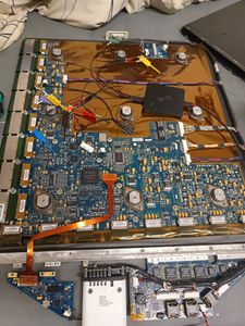 the Carbon fiber sleeve is held by 9 screws and can taken off without force.
 -
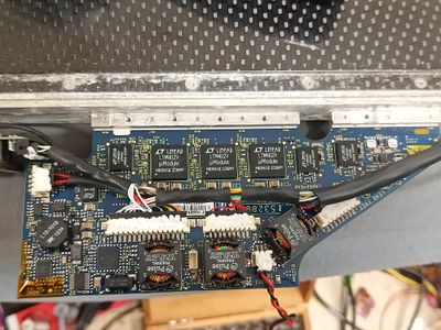 Power supply PCB
 -
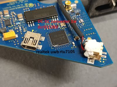 UWB PCB for Wireless USB using a RTU7105
 -
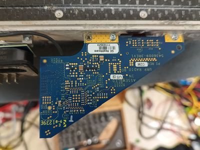 Backside of UWB PCB
 -
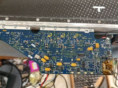 Backside of Power supply PCB
 -
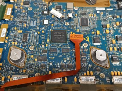 Main area of the PCB with its Altera Cyclone 3 FPGA
 -
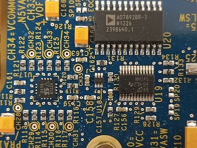 AD7892 is a 600ksps 12bit ADC, SN74LVC8T245 a 8bit bus transceiver and DG9408EDN a 8ch MUX
 -
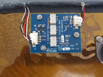 Isolation PCB for bottom connector
 -
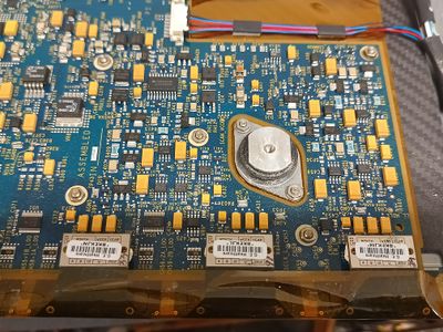 Powersupply section for FPGA and ROIC
 -
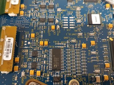 AD9764AR 14-Bit, 125 MSPS DAC and DS1682 integrated elapsed-time recorder
 -
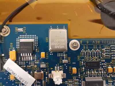 Accelerometer is a 834-0500 500G 3 Axis unit, and TJ500AE SPDT gigabit LAN switch
 -
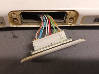 bottom connector for docking stand
 -
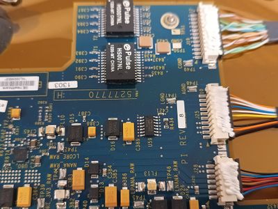 Ethernet transformers and ADM34 RS-485/RS-422 Transceiver
 -
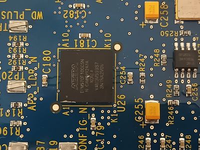 Altera EPM570f100c5n CPLD
 -
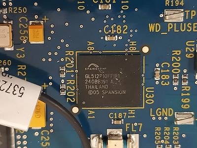 Spansion GL512P10FF1R1 512 Mbit NOR flash IC holding everything
 -
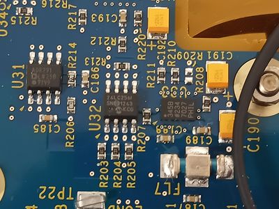 24LC256I 32k EEPROM for storing the accelerometer events


