Landis+Gyr Residential Meter: Difference between revisions
Jump to navigation
Jump to search
No edit summary |
Added Gen5 Meter Board |
||
| Line 1: | Line 1: | ||
<gallery> | Generation 4 and older boards based on M16C processor<gallery> | ||
File:LandisGyr PCB Blank1.JPG|Blank PCB Components side | File:LandisGyr PCB Blank1.JPG|Blank PCB Components side | ||
File:LandisGyr PCB Blank2.JPG|Blank PCB Screen and Buttons side | File:LandisGyr PCB Blank2.JPG|Blank PCB Screen and Buttons side | ||
| Line 8: | Line 8: | ||
File:LandisGyr PWB-72127 RevA Bot.JPG|Dual board meter, older design, metering board top | File:LandisGyr PWB-72127 RevA Bot.JPG|Dual board meter, older design, metering board top | ||
File:LandisGyr PWB-72127 RevA Top.JPG|Dual board meter, older design, metering board bottom | File:LandisGyr PWB-72127 RevA Top.JPG|Dual board meter, older design, metering board bottom | ||
</gallery> | |||
----<gallery> | |||
File:LandisGyr PCB 24-2411 RevAC TopScreen.JPG|Top of Gen5 meter board with LCD screen | |||
File:LandisGyr PCB 24-2411 RevAC TopNoScreen.JPG|Top of Gen5 meter board with the LCD screen removed | |||
File:LandisGyr PCB 24-2411 RevAC Bottom.JPG|Bottom of Gen5 meter board, ATSAM4C32 processor is under the large brown capacitor seen in the bottom middle of the PCB. | |||
File:LandisGyr PCB 24-2411 RevAC JTAGSolderPoints.jpeg|Red circled spots are missing 0 ohm resistors you need to solder bridge to enable JTAG connector to function. | |||
</gallery> | </gallery> | ||
Revision as of 00:21, 18 April 2022
Generation 4 and older boards based on M16C processor
-
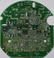 Blank PCB Components side
 -
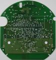 Blank PCB Screen and Buttons side
 -
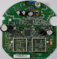 PCB with EM250 Zigbee chip and lower accuracy Teridian chip
 -
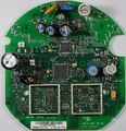 PCB with EM357 Zigbee chip and higher accuracy Teridian chip
 -
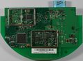 Dual board meter, older design, brain/network board top
 -
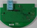 Dual board meter, older design, brain/network board bottom
 -
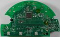 Dual board meter, older design, metering board top
 -
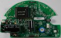 Dual board meter, older design, metering board bottom


-
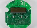 Top of Gen5 meter board with LCD screen
 -
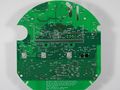 Top of Gen5 meter board with the LCD screen removed
 -
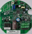 Bottom of Gen5 meter board, ATSAM4C32 processor is under the large brown capacitor seen in the bottom middle of the PCB.
 -
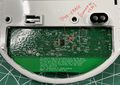 Red circled spots are missing 0 ohm resistors you need to solder bridge to enable JTAG connector to function.


