DFM-17 Radiosonde: Difference between revisions
→Photos: Add another image showing a better view of the underside of the PCB |
Added additional photos, added some new information regarding MCU I/O |
||
| Line 20: | Line 20: | ||
*Error Correction: Code-spreading, interleaving | *Error Correction: Code-spreading, interleaving | ||
*SoC: STM32F100R8T6B, 24MHz, 8KB RAM, 64KB Flash | *SoC: STM32F100R8T6B, 24MHz, 8KB RAM, 64KB Flash | ||
*GPS: | *GPS: U-Blox MAX-M8C-0-10 | ||
*Transmitter: Si4063 | *Transmitter: Si4063 | ||
=== Peripheral attachment points === | |||
* U-Blox GPS is attached to USART_2 on the STM32 via pins PA2 and PA3 | |||
* External serial port (USB connector) is attached to USART_1 (PA9 and PA10), sharing TX/RX with the external I²C bus. | |||
<br /> | <br /> | ||
| Line 31: | Line 36: | ||
File:DFM-17 NOAA Label.jpg|The label sticker NOAA(US) puts on the back of their DFM-17 radiosondes | File:DFM-17 NOAA Label.jpg|The label sticker NOAA(US) puts on the back of their DFM-17 radiosondes | ||
File:Dfm17-2layers.png|A view of the DFM-17 Radiosonde showing both layers to better assist tracing connections while reverse engineering the hardware. | File:Dfm17-2layers.png|A view of the DFM-17 Radiosonde showing both layers to better assist tracing connections while reverse engineering the hardware. | ||
File:Label id speculaton.jpg|Possible meanings of the internal labels and values. The date code in particular which may be useful to date production times. NWS sondes have the same cryptic string printed on the outside of the sonde where the mfg. date normally is on other countries'. "TU" may just indicate the board comes with sensors according to a third party source. | |||
File:Sensor stalk pinout.jpg|Pinout of the DFM-17 sensor stalk. Not all pins are used, and some seemingly are connected to a trace but end abruptly. | |||
</gallery> | </gallery> | ||
| Line 46: | Line 53: | ||
==Reassembly== | ==Reassembly== | ||
<br /> | |||
#Insert two fresh CR123A batteries into the board. | #Insert two fresh CR123A batteries into the board. | ||
Revision as of 03:24, 14 December 2022
The DFM-17 is a balloon-launched radiosonde manufactured by GRAW Radiosondes GmbH & Co. KG, and used for meteorological sounding.

Overview
The DFM-17 radiosonde succeeds the DFM-09 radiosonde. Graw began a contract with NOAA in the US to provide radiosondes. As of Late 2021, several sites have made the transition as part of NOAA’s Operational Test and Evaluation (OT&E) program. 45 CONUS sites are expected to use these radiosondes in early 2022. [1]
Specs [2]
- Weight: 63g
- Size: 90 x 67 x 44 mm
- Power supply: 2 CR123A batteries
- Estimated runtime: ~240 minutes
- Transmission rate: 1 packet/sec
- Bandwidth: ~10 kHz (Website lists <12)
- Frequency range: 400 - 405.99 MHz
- Modulation: GFSK
- TX Power: ~100mW
- Error Correction: Code-spreading, interleaving
- SoC: STM32F100R8T6B, 24MHz, 8KB RAM, 64KB Flash
- GPS: U-Blox MAX-M8C-0-10
- Transmitter: Si4063
Peripheral attachment points
- U-Blox GPS is attached to USART_2 on the STM32 via pins PA2 and PA3
- External serial port (USB connector) is attached to USART_1 (PA9 and PA10), sharing TX/RX with the external I²C bus.
Photos
-
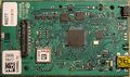 Internal view of the DFM-17
 -
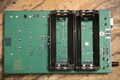 The bottom side of the PCB in the DFM-17
 -
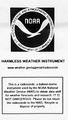 The label sticker NOAA(US) puts on the back of their DFM-17 radiosondes
 -
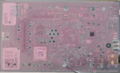 A view of the DFM-17 Radiosonde showing both layers to better assist tracing connections while reverse engineering the hardware.
 -
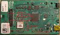 Possible meanings of the internal labels and values. The date code in particular which may be useful to date production times. NWS sondes have the same cryptic string printed on the outside of the sonde where the mfg. date normally is on other countries'. "TU" may just indicate the board comes with sensors according to a third party source.
 -
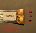 Pinout of the DFM-17 sensor stalk. Not all pins are used, and some seemingly are connected to a trace but end abruptly.


Disassembly
- Examine rope, parachute and parachute rigging lines for viability. Neatly organize the flight rigging if usable. Discard if not viable for reuse.
- Cut the zip tie surrounding the Styrofoam from the top portion by the rope loop.
- Pull the rope loop out, there should be little to no resistance.
- Make a slice in the sticker[3] where the two pieces of Styrofoam meet.
- Pull apart the two Styrofoam pieces to reveal the circuit board.
- Pull the circuit board out. There will be some resistance.
- The board is now separated from the Styrofoam shell, reuse if desired.
- Pull the two CR123A batteries out, keep or discard them. The board can run off USB power. Batteries are not necessary for development on this board.
Reassembly
- Insert two fresh CR123A batteries into the board.
- Line up the board to the IO cutouts in the Styrofoam, begin to push into the slots. Make sure the antenna wire comes through.
- Press the top piece of Styrofoam into place.
- Tape or apply another sticker onto the back label. (Optional)
- Insert the plastic rope loop piece.
- zip tie the shell together, the zip tie end should end up on the edge nearest to the power button.
- Rope on a balloon/drone/kite/etc.. to the rope loop.
- Power on the device by pressing and holding the button, you will see a yellow light blink, hold until the light turns solid.
Mini USB Port
The mini USB port on the board does not use the USB protocol for communication, it is a UART bus. However using USB to power the board should not harm the board in theory.
In order to use it, splice a USB cable and wire up a USB<->TTL adapter with the following pins:
- VBUS: 5 Volts DC
- D-: TX
- D+: RX
- GND: GND
The board will communicate with the official GRAWMET software using this approach. Reverse engineering of the port's protocol is underway, however it is believed to use a similar, if not the same protocol the PS-15 uses.
Hardware modifications

The DFM-17 has solder pads for an SMA port and a SWD header.
An Adafruit Skinny SWD SMT connector and a generic SMA connected was used in the photo.
Developing and Programming the board

When lab testing, you can power the board from the USB header. It also appears to run fine supplying 3.3V to the SWD port(STLink clones do this).
The board uses a STM32, and requires a ST-Link to program. The process used to upload code to the MCU is the same as the Vaisala RS41 radiosonde, you will need to solder and connect the VTRef(3.3V), Ground, SWDIO, SWDCLK and RST pins to your ST-Link.
The board can run without external power being supplied when programming. This board has read-out protection enabled similar to the RS41 and this must be disabled before you can flash firmware to the board.
- ↑ GRAW delivers to USA NOAA/National Weather Service. GRAW Radiosondes GmbH & Co. KG. Retrieved 17 November 2021.
- ↑ https://www.graw.de/products/radiosondes/dfm-17/
- ↑ File:DFM-17 NOAA Label.jpg