Teardown Video
5 minute video showing all the parts of the LIDAR and how they go together, helps to understand all the parts and pieces pictured below.
Teardown PCB Pictures
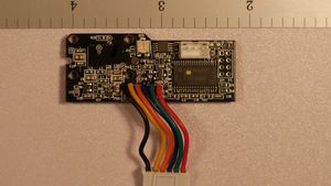
LIDAR CMOS sensor and DSP board - top side
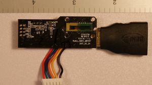
LIDAR CMOS sensor and DSP board - bottom side (don’t mind the BENFEI connector on the right side, used to steady PCB for picture)
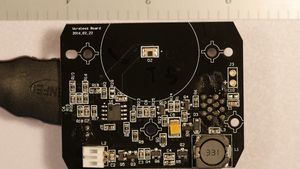
Wireless receiver board - top
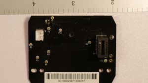
Wireless receiver board - bottom
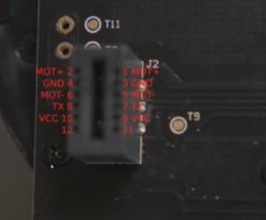
Pinout of connector on Power Board that connects to Roborock S5
Teardown Mechanical Pictures
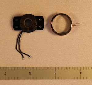
Inductors used for wireless power
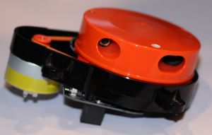
Laser and Lens housing module, CMOS sensor board mounts to this
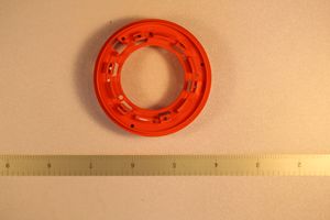
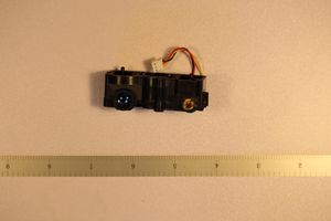
Rotating housing - bottom
Analysis of Hardware
To be completed
Additional/Novel Uses
To be completed


