File list
Jump to navigation
Jump to search
This special page shows all uploaded files.
| Date | Name | Thumbnail | Size | User | Description | Versions |
|---|---|---|---|---|---|---|
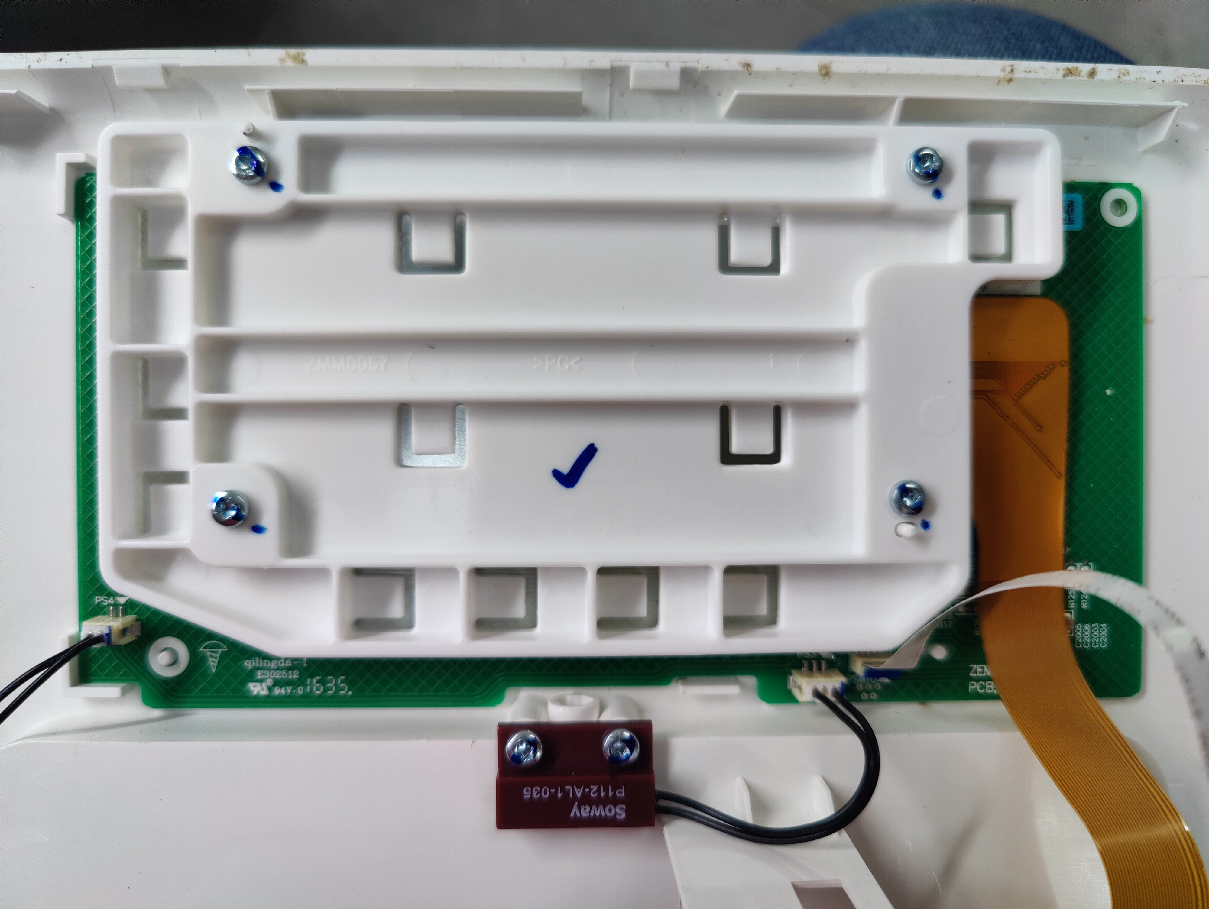
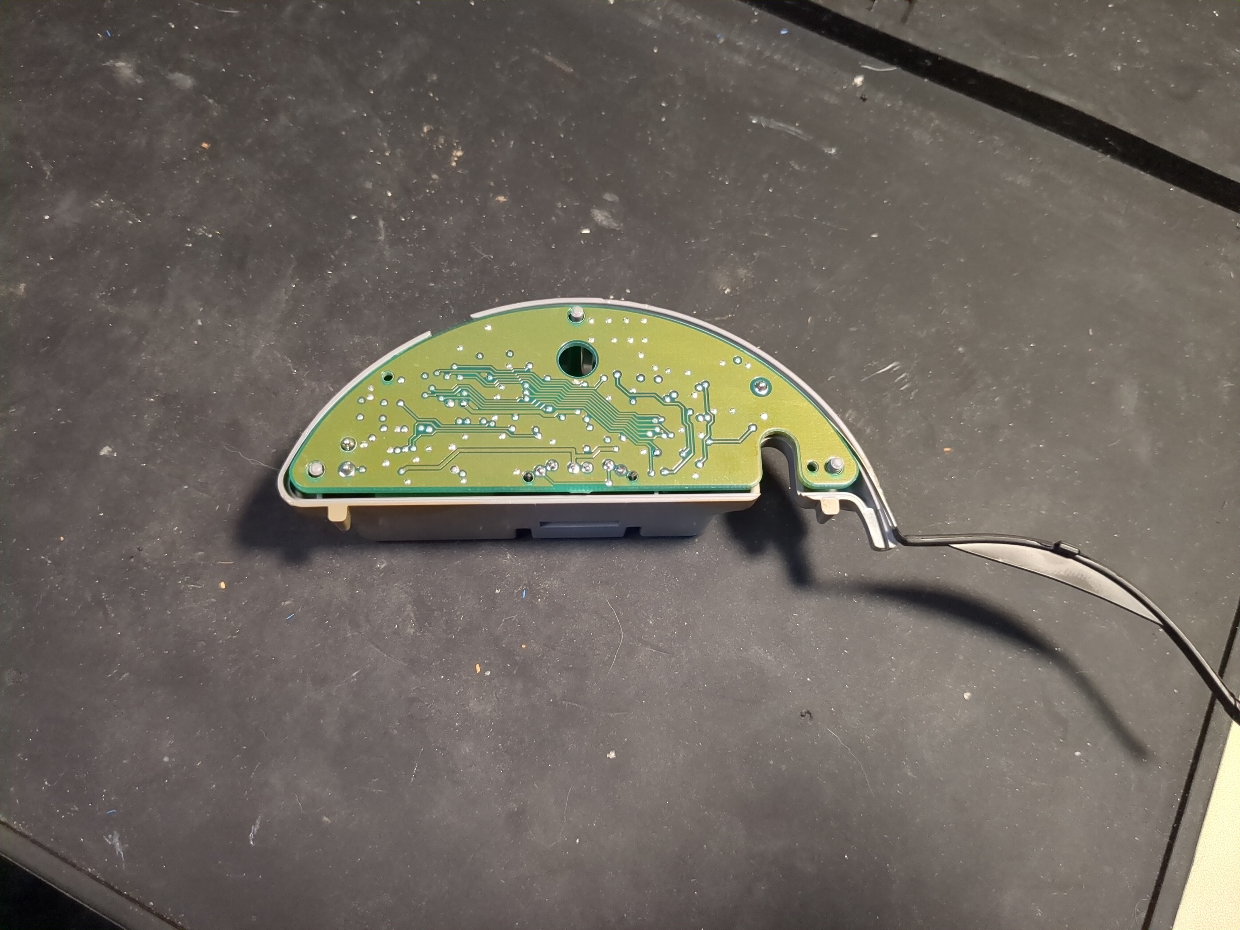
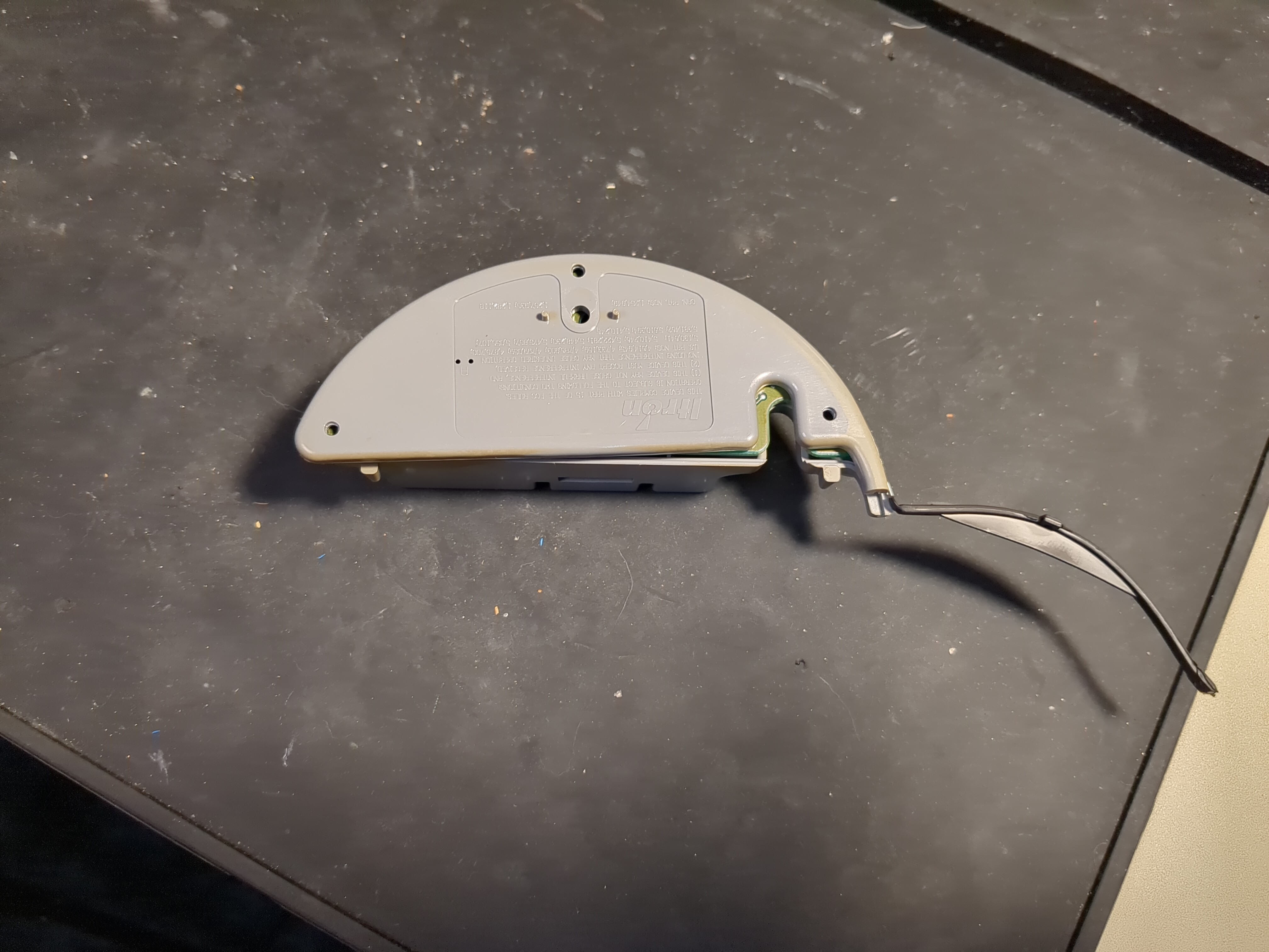
| 06:00, 7 September 2024 | Roti rotimatic front panel back.jpg (file) |  |
5.77 MB | -.-6eau | Main panel LCD and capacitive touch button assembly. Attached with 4 torx screws. One of two door closed sensors shown, PS4 connection on left goes to second sensor. | 1 |
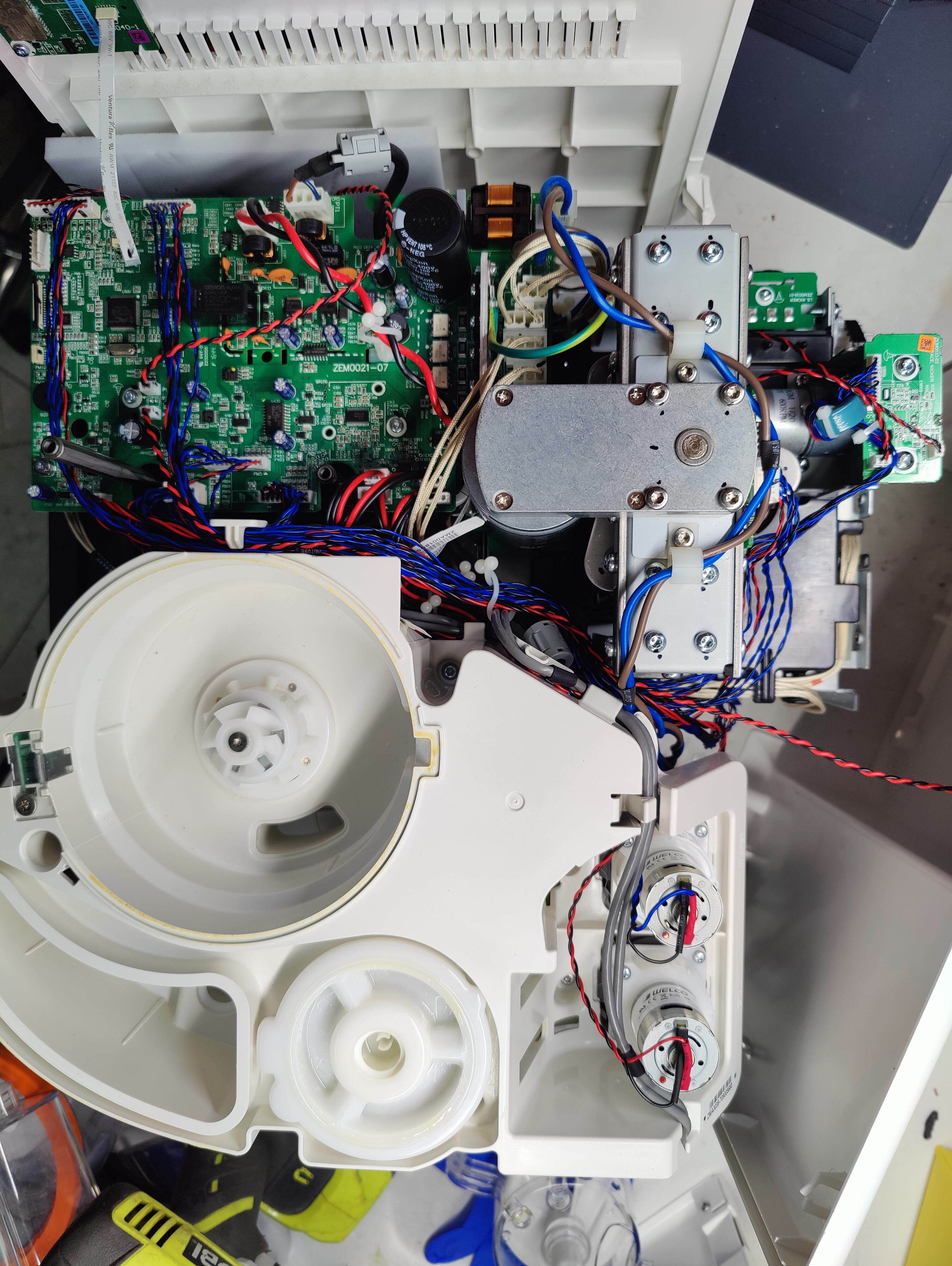
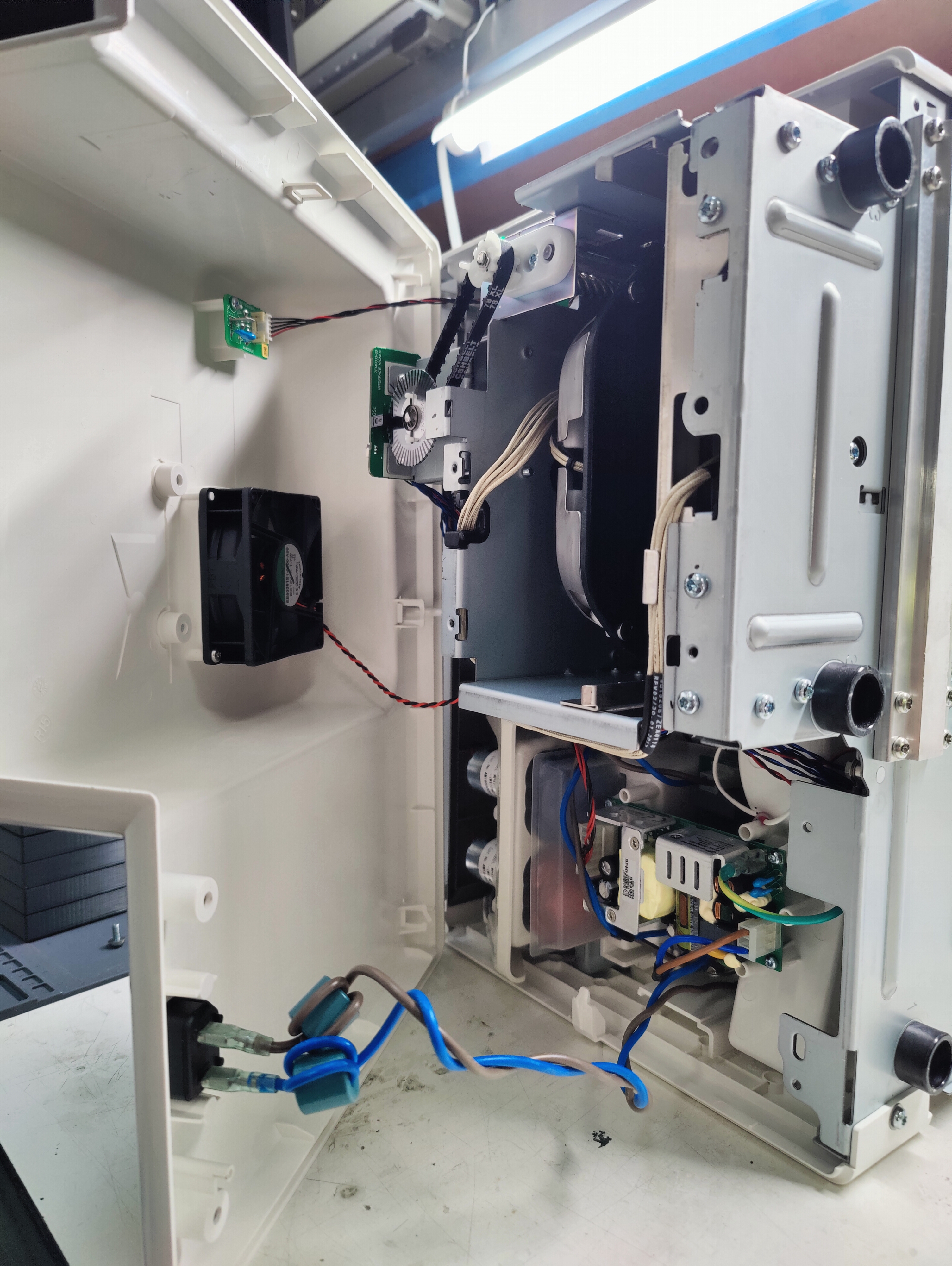
| 05:53, 7 September 2024 | Roti rotimatic top no cover.jpg (file) |  |
7.15 MB | -.-6eau | View of entire machine from the top with cover, front and back panels removed. Note side panel with wireless module flat flex at top left. 2 twisted pairs of red/black wires connecting in lower middle left of main board. Upper pair goes to side panel. Lower pair goes to rear fan (right side of picture). Front panel screen flex connector towards top of left edge of board, next to buttons flat flex just below it. Two mains pairs of AC wires brown/blue independently routed one directly to right... | 1 |
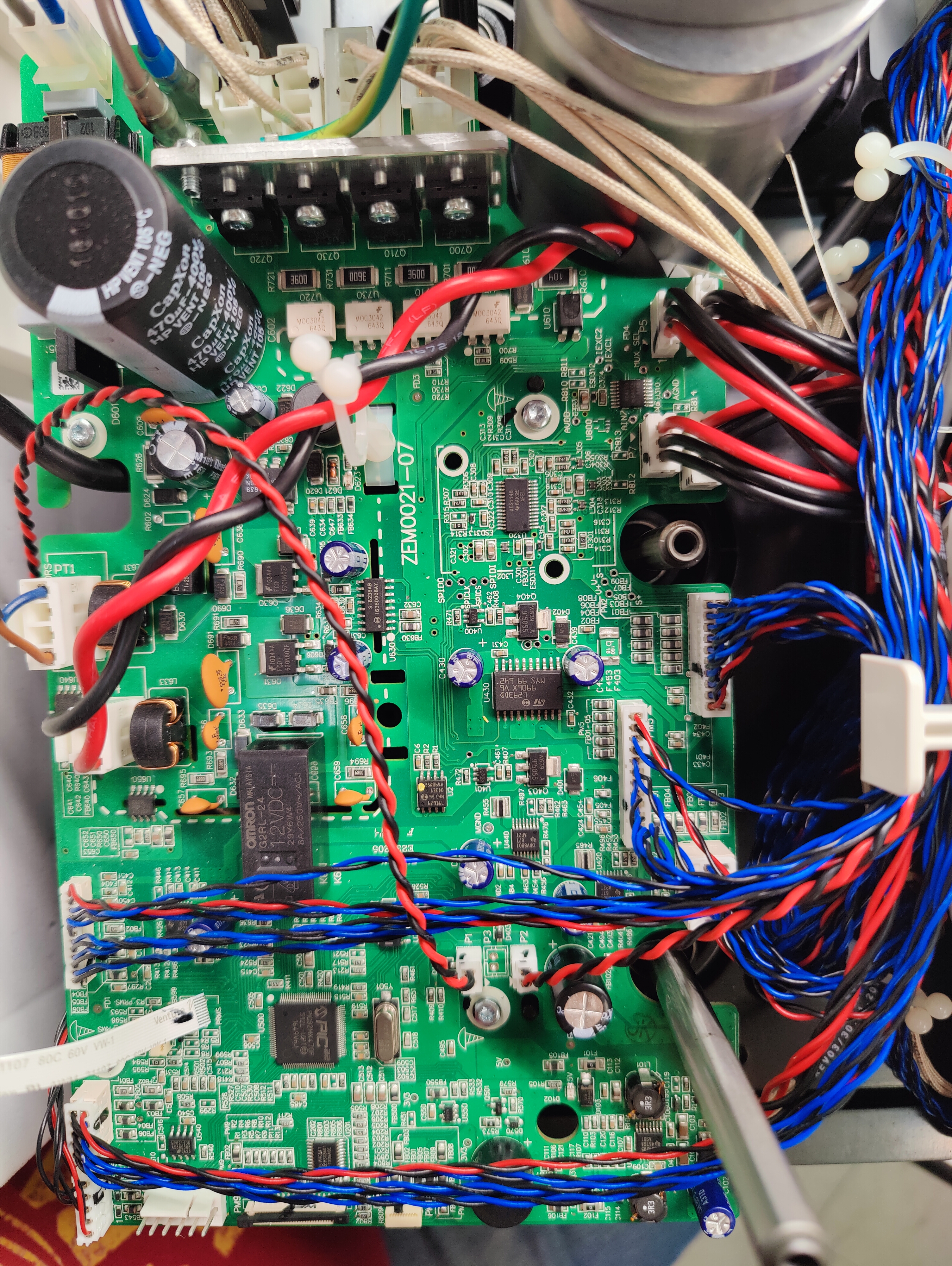
| 05:38, 7 September 2024 | Roti rotimatic main board PIC32MX470F512L.jpg (file) |  |
8.92 MB | -.-6eau | PCB: ZEM0021-07 PIC32MX470F512L-I/PT MIPS32® M4K™ PIC® 32MX Microcontroller IC 32-Bit Single-Core 80MHz 512KB (512K x 8) FLASH 100-TQFP (12x12) | 1 |
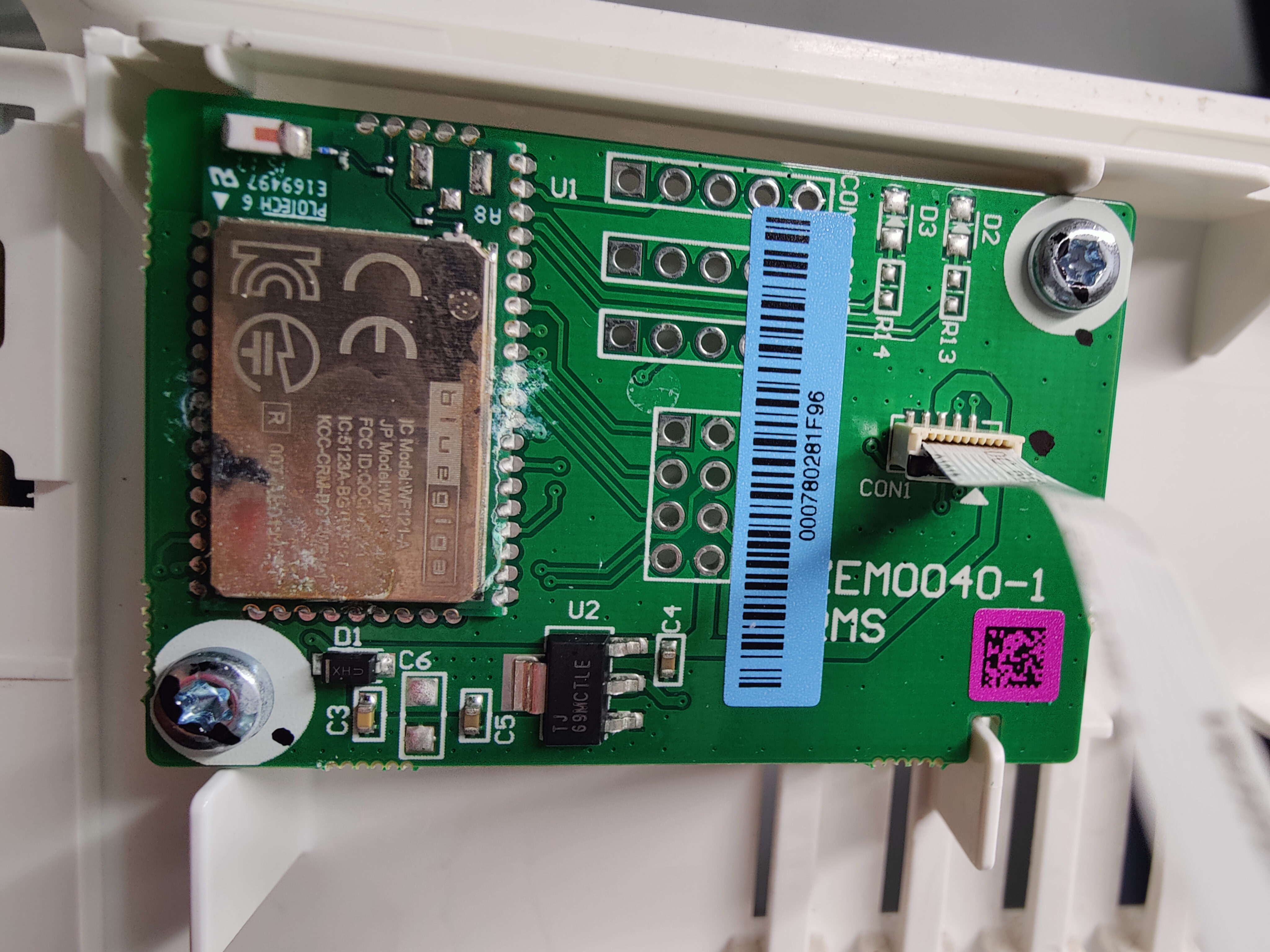
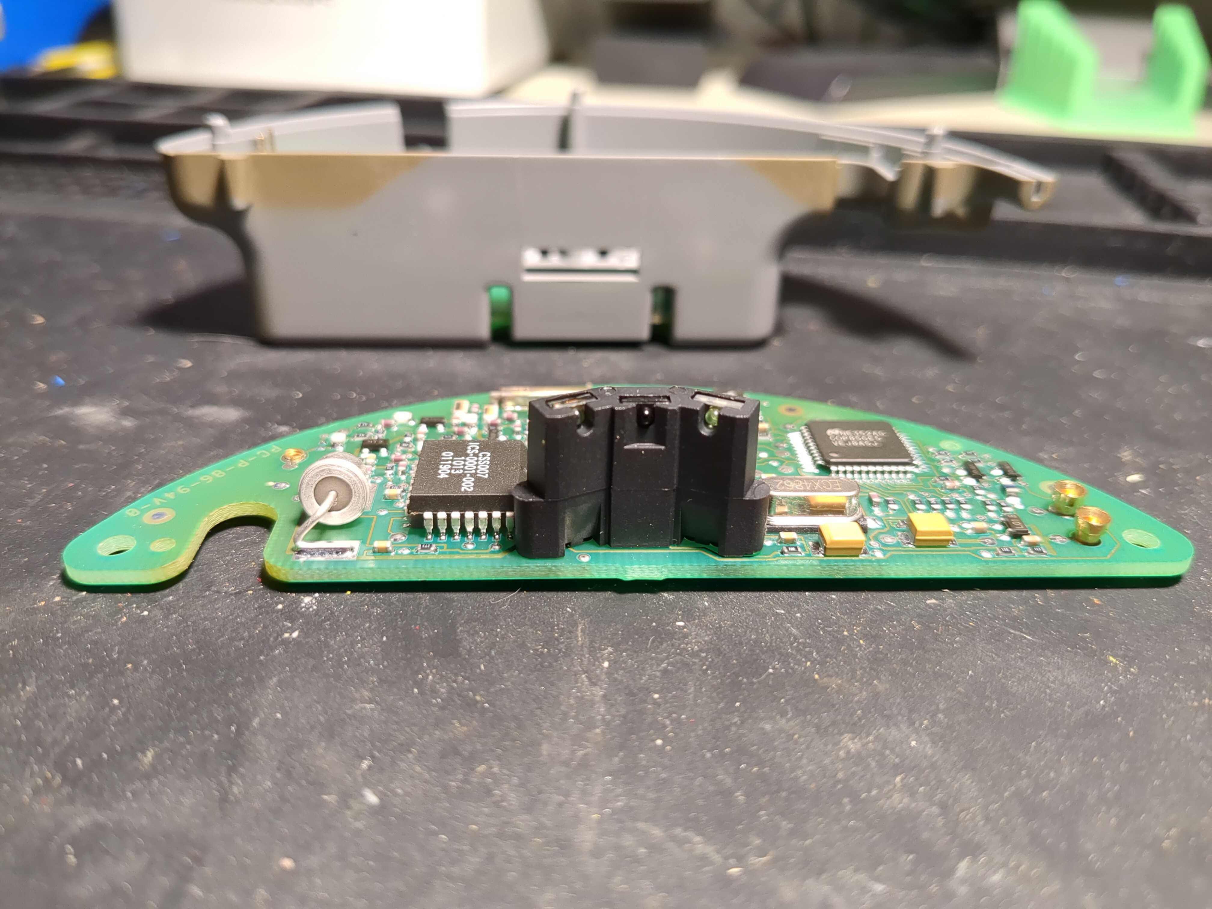
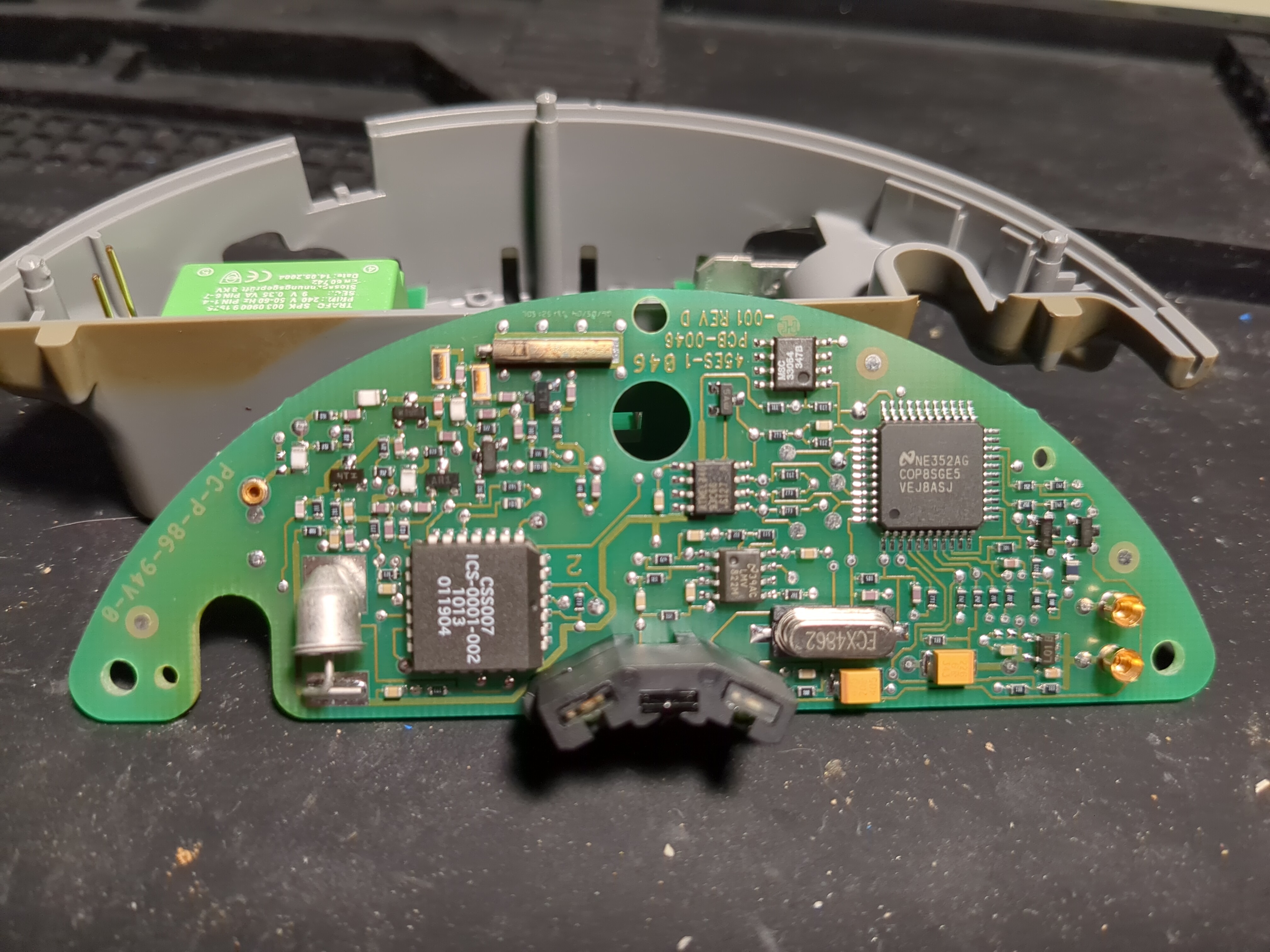
| 05:33, 7 September 2024 | Roti rotimatic bluegiga WF121-A.jpg (file) |  |
6.06 MB | -.-6eau | Wireless board with 802.11 b/g/n bluegiga module and flat flex connector. | 1 |
| 05:29, 7 September 2024 | Roti rotimatic under rear cover.jpg (file) |  |
5.97 MB | -.-6eau | Opening rear cover after popping plastic latches and removing T20 screw from bottom. Fan wiring passes to connector on top of main board, one of two. Upper board with 5 wires is external USB connector, presumably for thumb stick to reflash firmware. 2 wire AC mains, brown and blue with ferrites. Not shown reset-able 2 prong plug for connecting to outlet. | 1 |
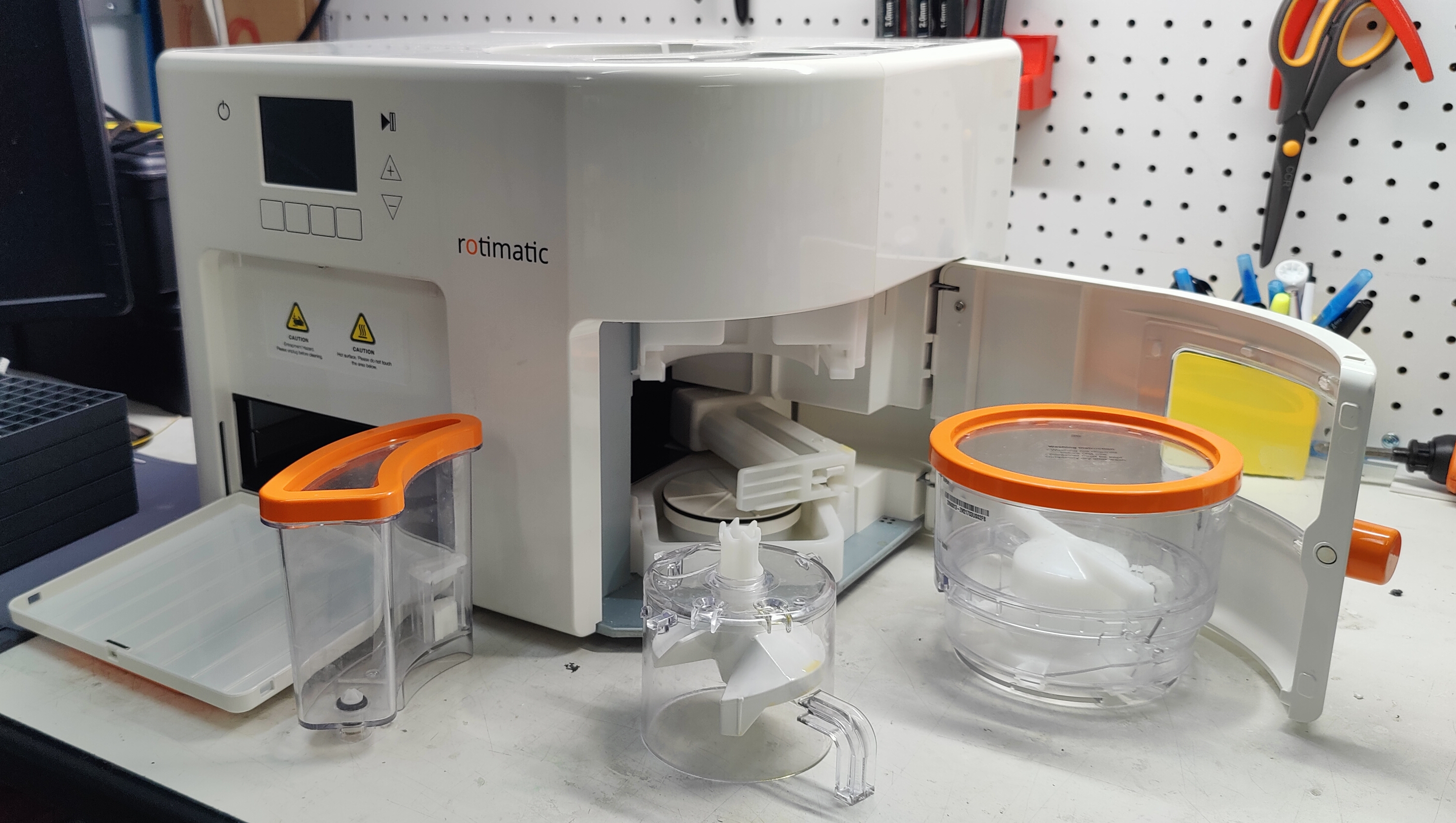
| 05:17, 7 September 2024 | Roti rotimatic complete set.jpg (file) |  |
2.96 MB | -.-6eau | The entire device prior to further exploration. | 1 |
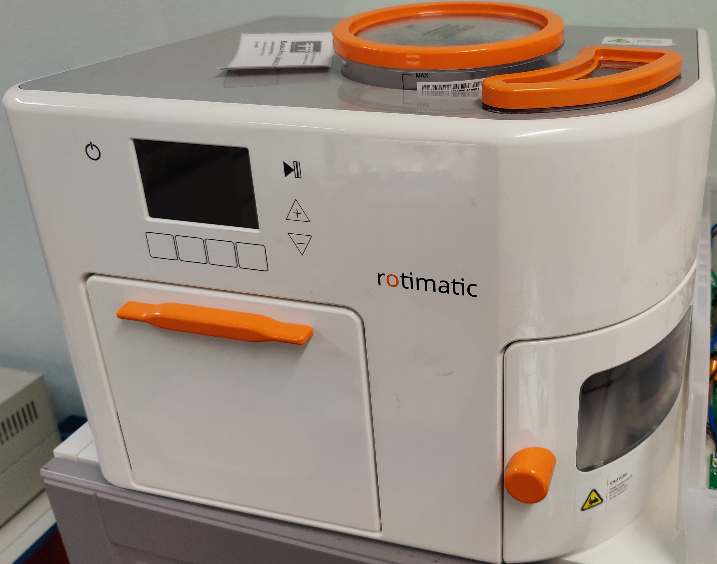
| 05:09, 7 September 2024 | Roti rotimatic plastic.jpg (file) |  |
3.08 MB | -.-6eau | Robot shell, only all of the plastic components "assembled". | 1 |
| 04:26, 7 September 2024 | Roti rotomatic Trouble powering on 0x6.jpg (file) |  |
138 KB | -.-6eau | Error message displayed when powering on September 2024. | 1 |
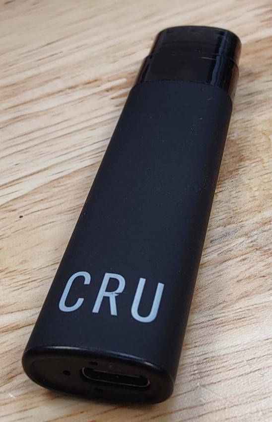
| 22:35, 5 September 2024 | Vape CRU Stick.jpeg (file) |  |
97 KB | -.-6eau | 1 | |
| 22:34, 5 September 2024 | Vape Cracked Open.jpeg (file) |  |
178 KB | -.-6eau | 1 | |
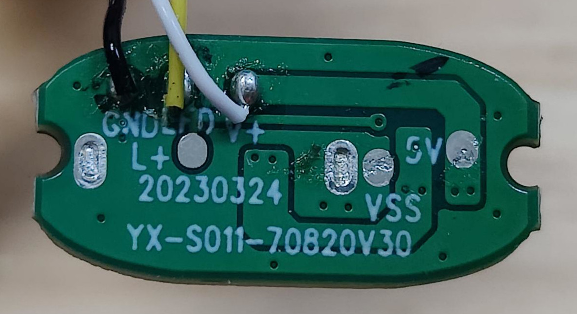
| 22:31, 5 September 2024 | Vape Mic Controller Back Close.jpeg (file) |  |
54 KB | -.-6eau | 1 | |
| 22:30, 5 September 2024 | Vape Mic Controller.jpeg (file) |  |
131 KB | -.-6eau | 1 | |
| 22:30, 5 September 2024 | Vape Naked Battery Charging.jpeg (file) |  |
275 KB | -.-6eau | 1 | |
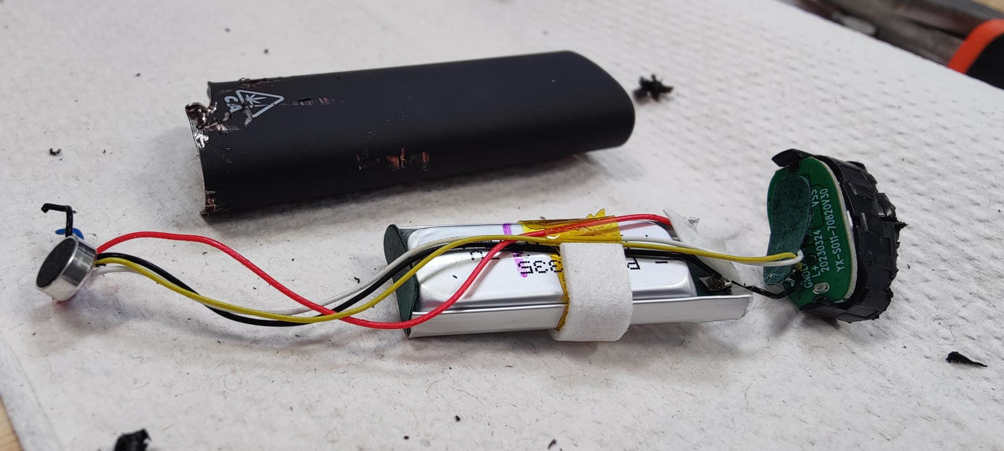
| 22:30, 5 September 2024 | Vape Torndown.jpeg (file) |  |
246 KB | -.-6eau | 1 | |
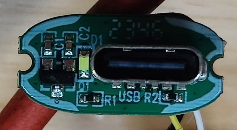
| 22:29, 5 September 2024 | Vape USB-C Board Back.jpeg (file) |  |
149 KB | -.-6eau | 1 | |
| 22:28, 5 September 2024 | Vape USB-C Board.jpeg (file) |  |
83 KB | -.-6eau | 1 | |
| 02:08, 17 August 2024 | Norcommnc401.pdf (file) | 3.33 MB | Trevor229 | PDF user manual for the Norcomm NC401 DTMF decoder module | 1 | |
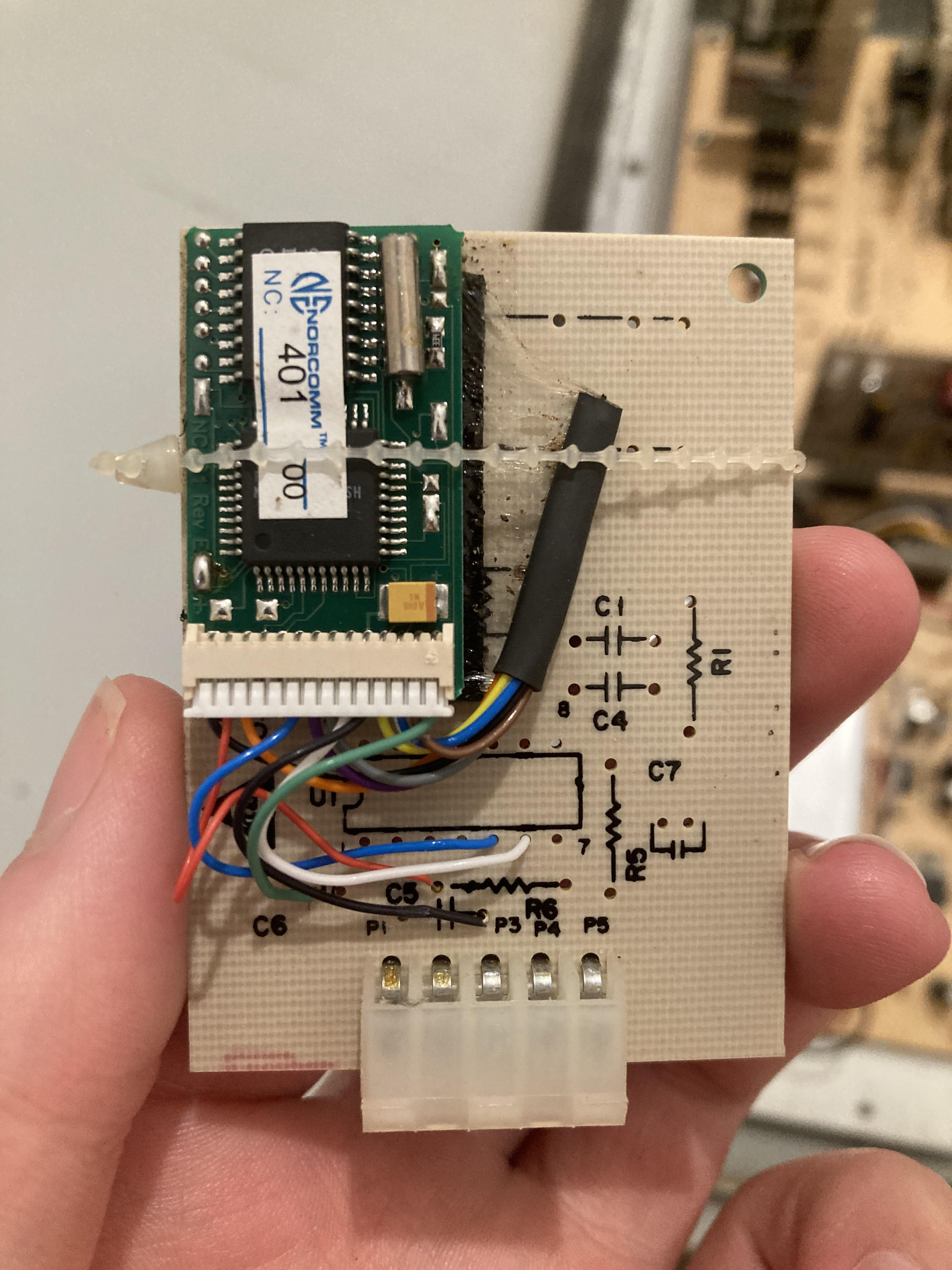
| 02:06, 17 August 2024 | Cdf decoder dtmf.jpg (file) |  |
1.26 MB | Trevor229 | A DTMF version of a CD&F tone decoder module | 1 |
| 23:56, 18 June 2024 | G1 V500L12 FZ-G1 UVW series.zip (file) | 110 KB | Polymorphic7 | EC firmware blob V5.00L12 for Panasonic FZ-G1 [U/V/W] series. Extracted from the binary "EcUpdate_G1_V500L12.exe" downloaded from "https://panasonic.com/". Copyrighted by Panasonic. For repair/research purpose only | 1 | |
| 23:43, 18 June 2024 | G1 V4.00L14 FZ-G1 PQR series.zip (file) | 113 KB | Polymorphic7 | EC firmware blob V4.00L14 for Panasonic FZ-G1 [P/Q/R] series. Extracted from the binary "EcUpdate_G1_V400L14.exe" downloaded from "https://panasonic.com/". Copyrighted by Panasonic. For repair/research purpose only. | 1 | |
| 19:49, 18 June 2024 | Fm2s 015.jpg (file) |  |
1.42 MB | Electrohead | 1 | |
| 19:49, 18 June 2024 | Fm2s 014.jpg (file) |  |
979 KB | Electrohead | 1 | |
| 19:48, 18 June 2024 | Fm2s 013.jpg (file) |  |
1.22 MB | Electrohead | 1 | |
| 19:48, 18 June 2024 | Fm2s 012.jpg (file) |  |
1.54 MB | Electrohead | 1 | |
| 19:47, 18 June 2024 | Fm2s 011.jpg (file) |  |
1.37 MB | Electrohead | 1 | |
| 19:47, 18 June 2024 | Fm2s 010.jpg (file) |  |
1.32 MB | Electrohead | 1 | |
| 19:46, 18 June 2024 | Fm2s 009.jpg (file) |  |
1.22 MB | Electrohead | 1 | |
| 19:46, 18 June 2024 | Fm2s 008.jpg (file) |  |
1.37 MB | Electrohead | 1 | |
| 19:37, 18 June 2024 | Fm2s 007.jpg (file) |  |
1.44 MB | Electrohead | 1 | |
| 19:36, 18 June 2024 | Fm2s 006.jpg (file) |  |
1.18 MB | Electrohead | 1 | |
| 19:36, 18 June 2024 | Fm2s 005.jpg (file) |  |
1.32 MB | Electrohead | 1 | |
| 19:35, 18 June 2024 | Fm2s 004.jpg (file) |  |
1.1 MB | Electrohead | 1 | |
| 19:35, 18 June 2024 | Fm2s 003.jpg (file) |  |
1.16 MB | Electrohead | 1 | |
| 19:33, 18 June 2024 | Fm2s 002.jpg (file) |  |
1.43 MB | Electrohead | 1 | |
| 19:31, 18 June 2024 | Fm2s 001.jpg (file) |  |
1.46 MB | Electrohead | 1 | |
| 00:29, 25 May 2024 | Maxon sd blank configs.zip (file) | 1 KB | Trevor229 | Blank configuration files for the Maxon SD-161/164 and SD-171/174 line of radios. | 1 | |
| 18:48, 23 May 2024 | Cdf SC hinge side.jpg (file) |  |
1.86 MB | Trevor229 | Hinge side of the SC series CD&F | 1 |
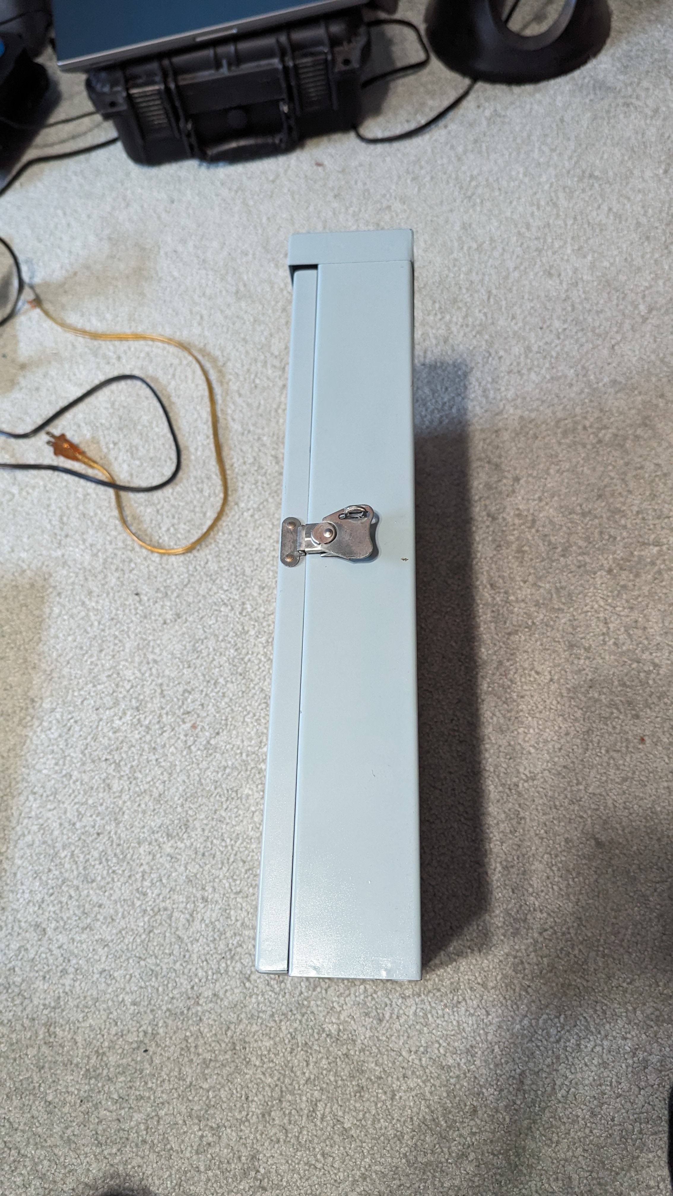
| 18:48, 23 May 2024 | Cdf SC latch side.jpg (file) |  |
2.28 MB | Trevor229 | Latch side of the SC series CD&F | 1 |
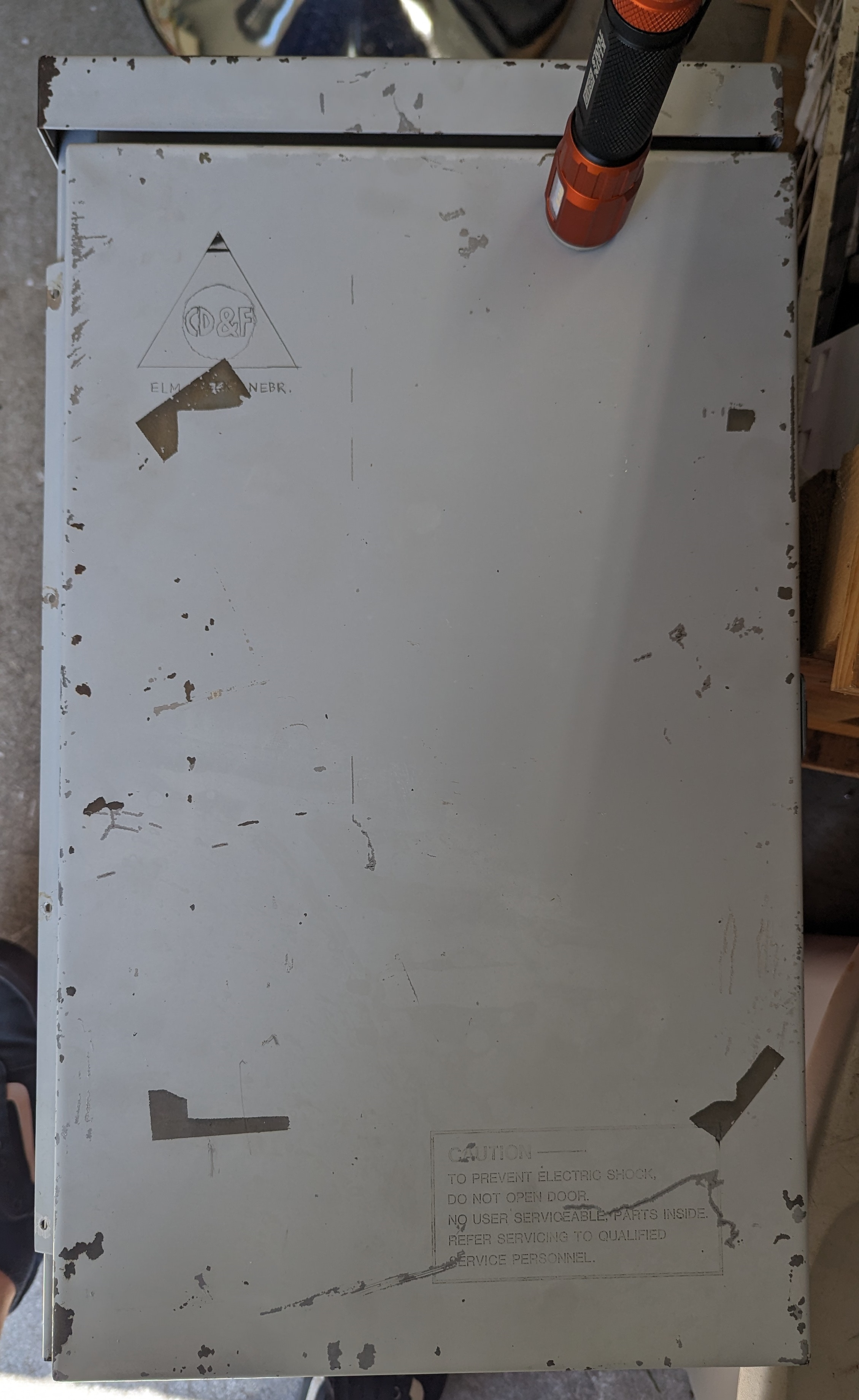
| 18:47, 23 May 2024 | Cdf SC back.jpg (file) |  |
1.39 MB | Trevor229 | Back of the SC series CD&F | 1 |
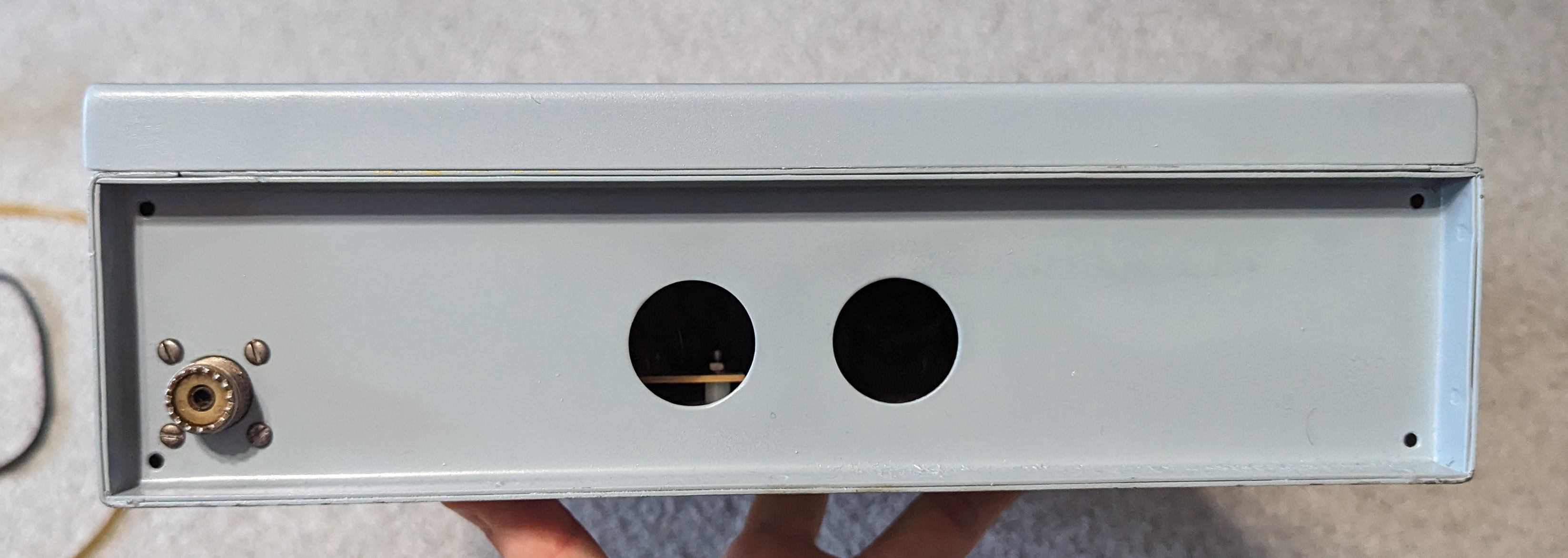
| 18:47, 23 May 2024 | Cdf SC bottom.jpg (file) |  |
551 KB | Trevor229 | Bottom of the SC series CD&F showing optional SO-239 | 1 |
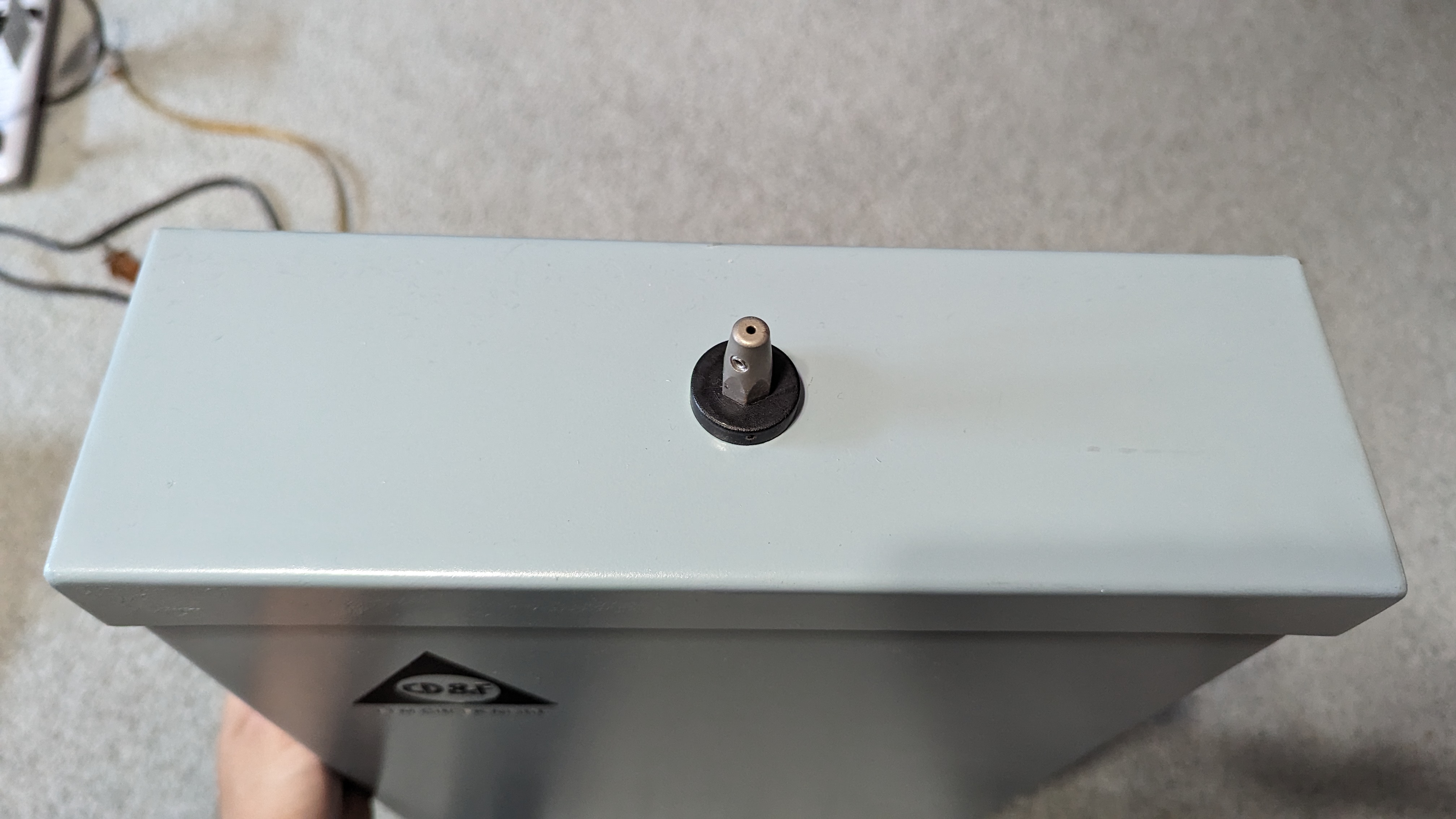
| 18:46, 23 May 2024 | Cdf SC top.jpg (file) |  |
1.46 MB | Trevor229 | Top of the SC series CD&F | 1 |
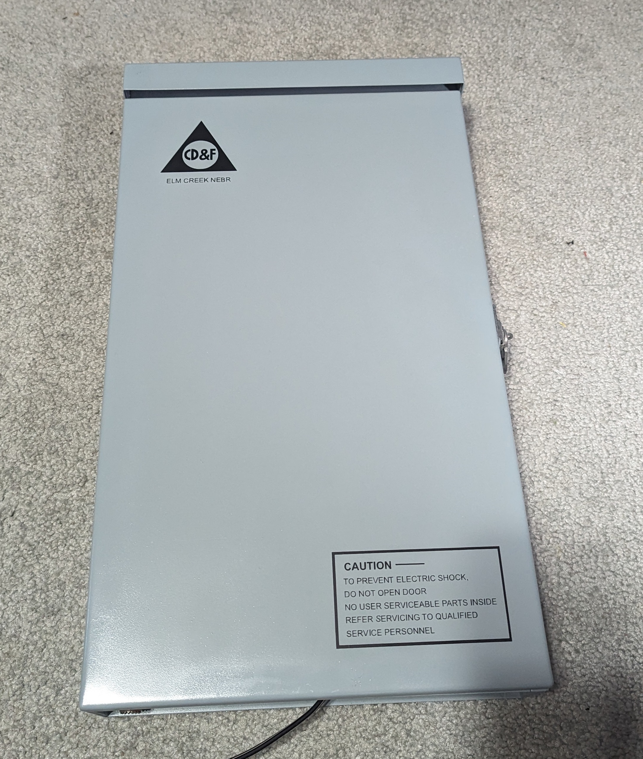
| 18:42, 23 May 2024 | Cdf SC front restored.jpg (file) |  |
1.76 MB | Trevor229 | Front of my SC series CD&F after restoration | 1 |
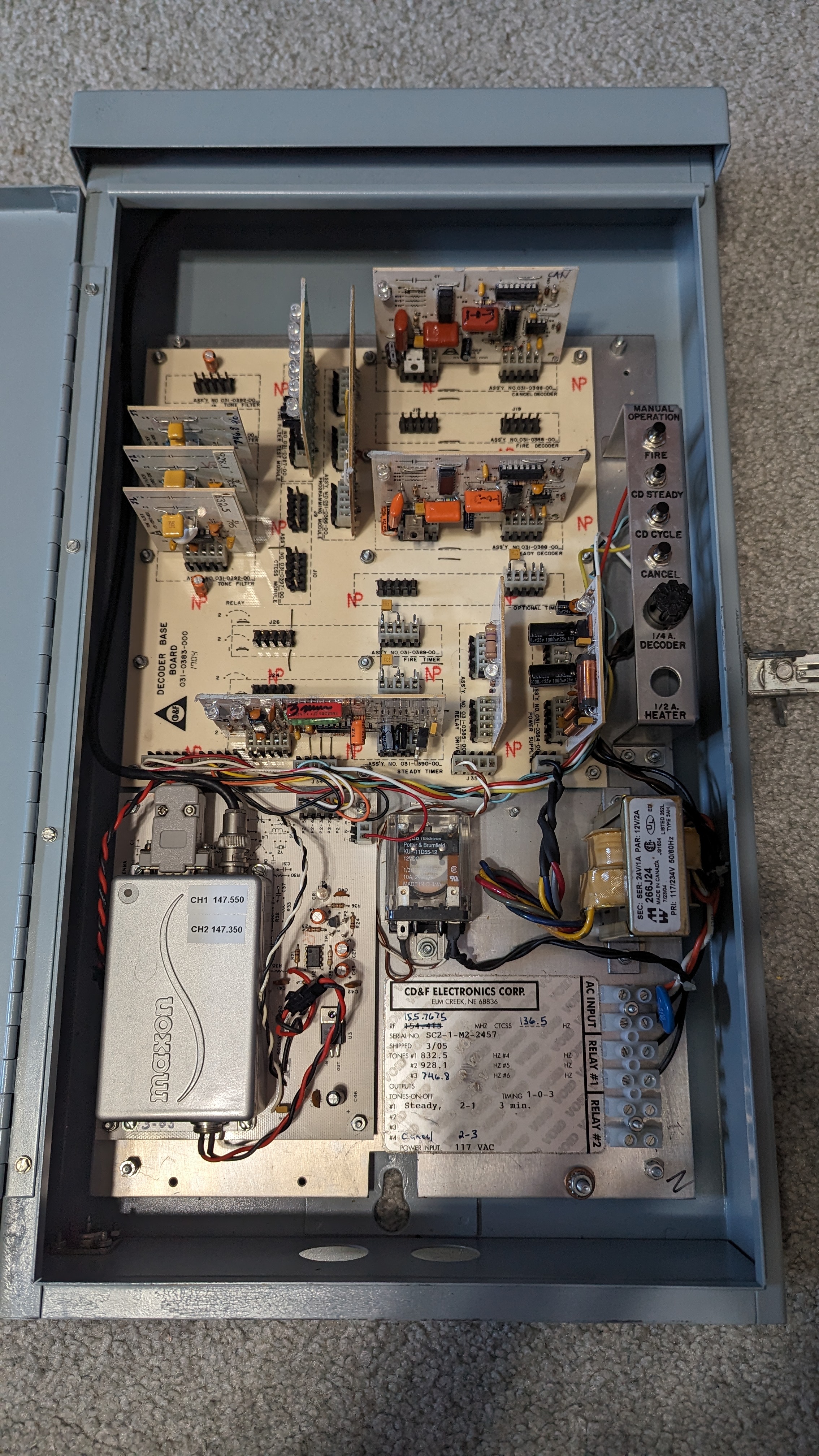
| 18:38, 23 May 2024 | Cdf SC inside.jpg (file) |  |
2.75 MB | Trevor229 | Inside of the SC series CD&F after restoration and adding missing control buttons | 1 |
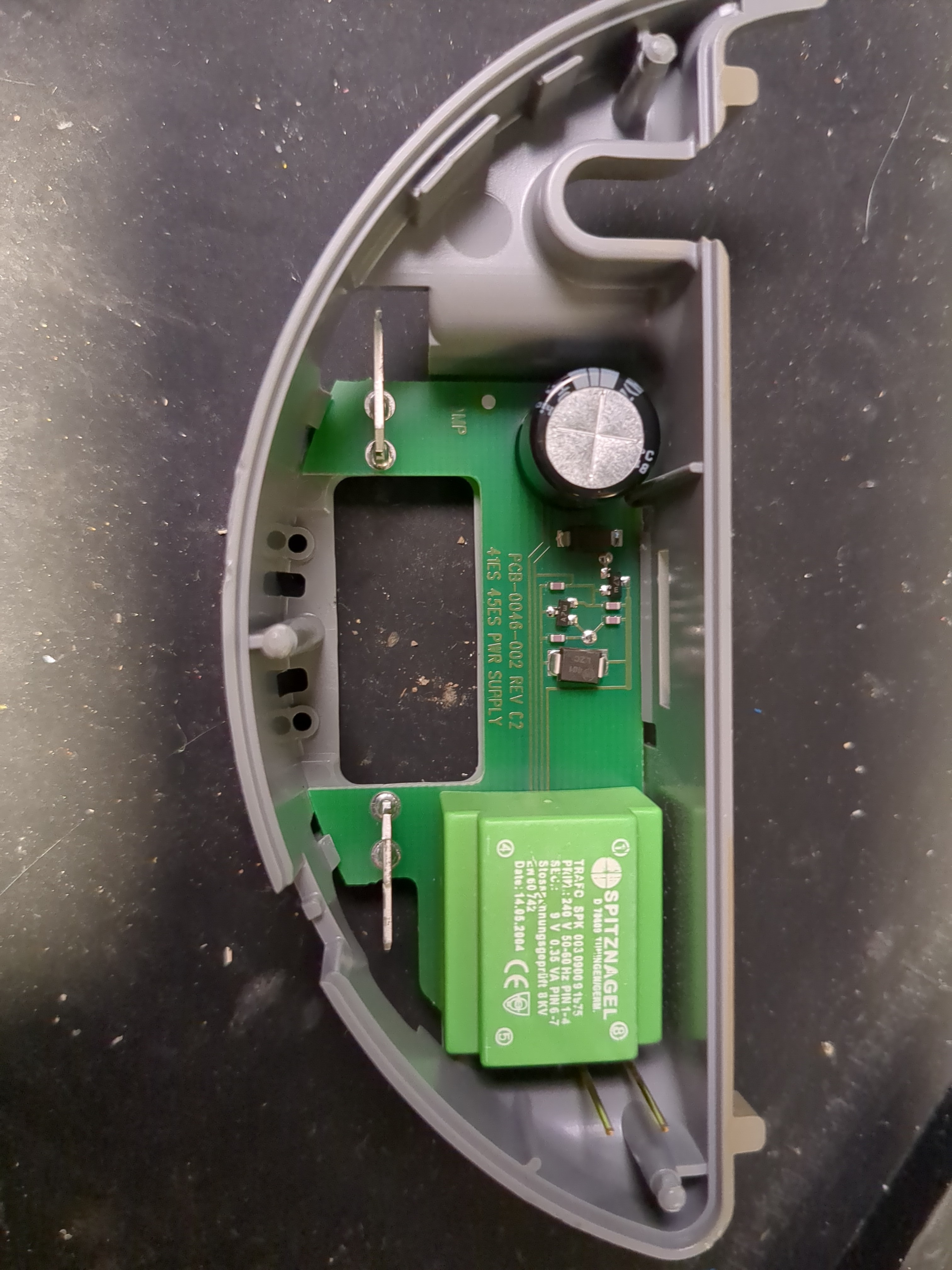
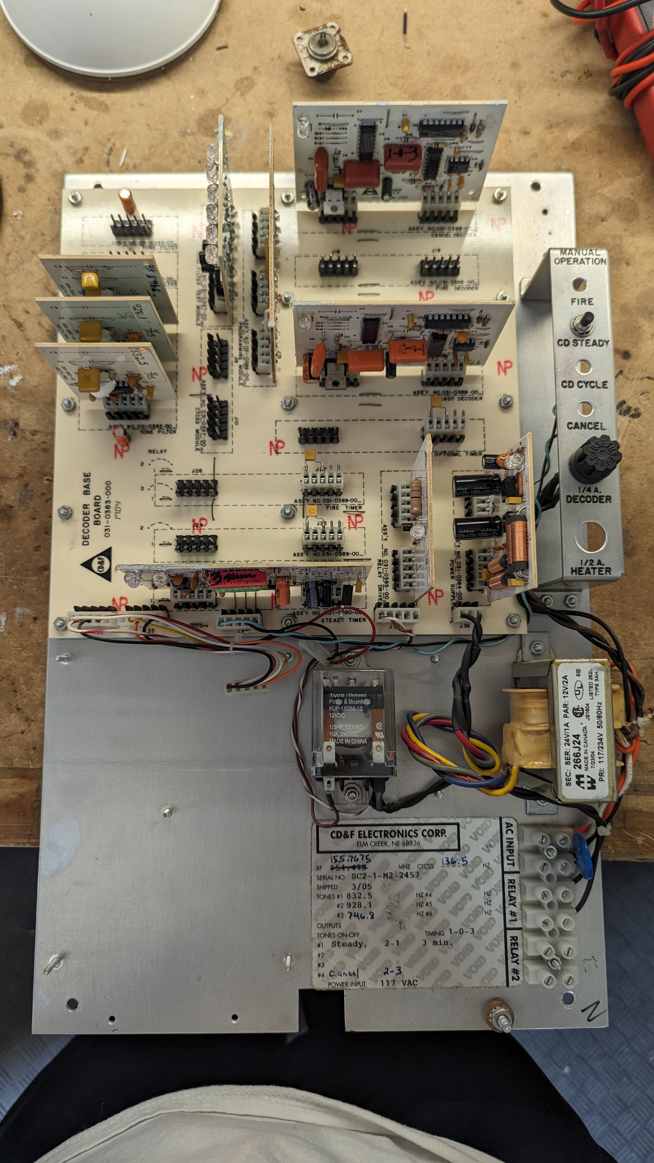
| 02:58, 23 May 2024 | Cdf SC assembly wo radio.jpg (file) |  |
2.13 MB | Trevor229 | Sub-assembly of the SC series CD&F without the radio receiver module installed | 1 |
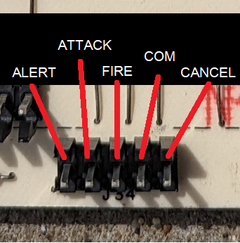
| 02:56, 23 May 2024 | Cdf SC Button conn pinout.png (file) |  |
114 KB | Trevor229 | Pinout of the local control header on the SC series CD&F | 1 |
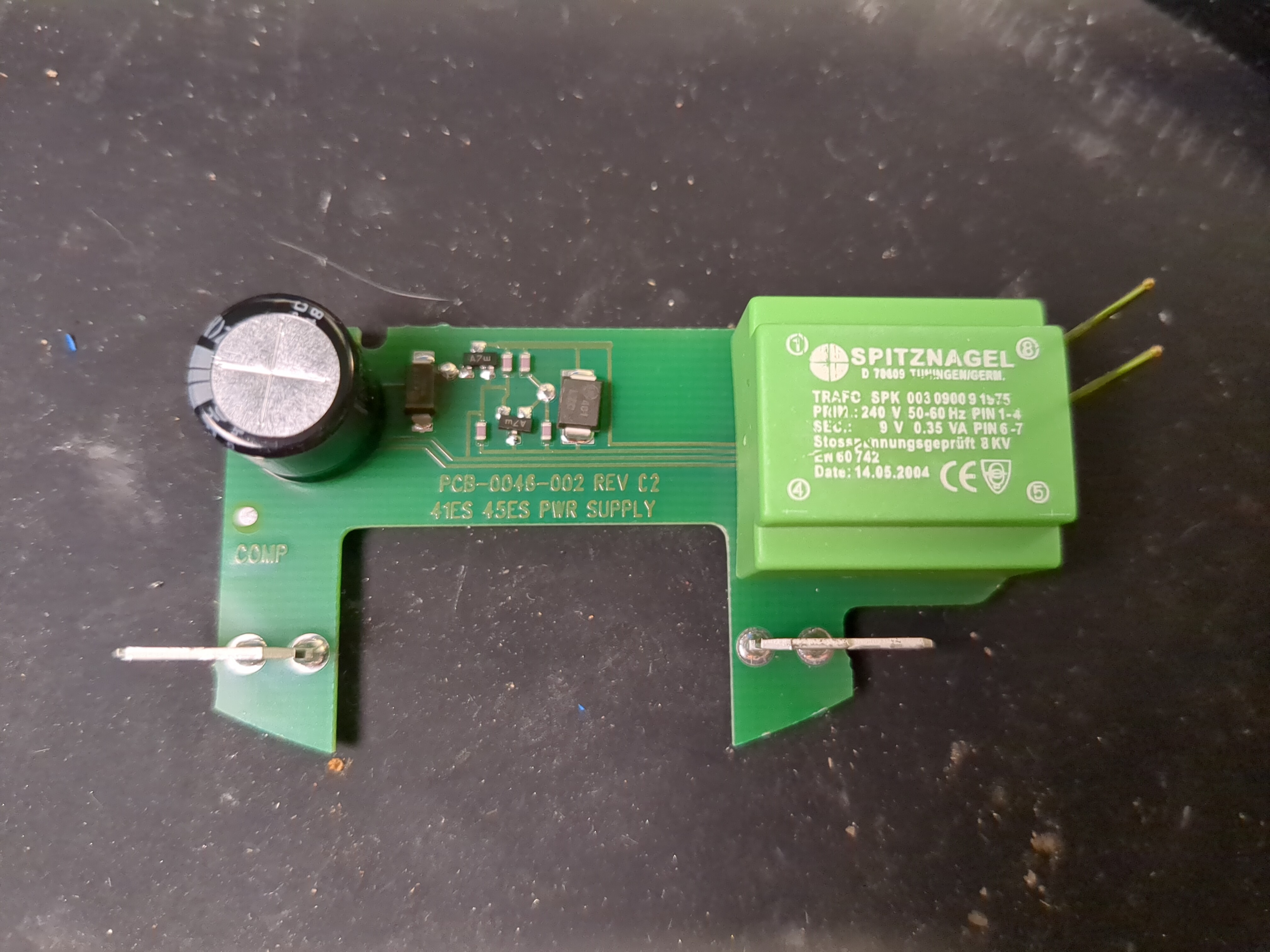
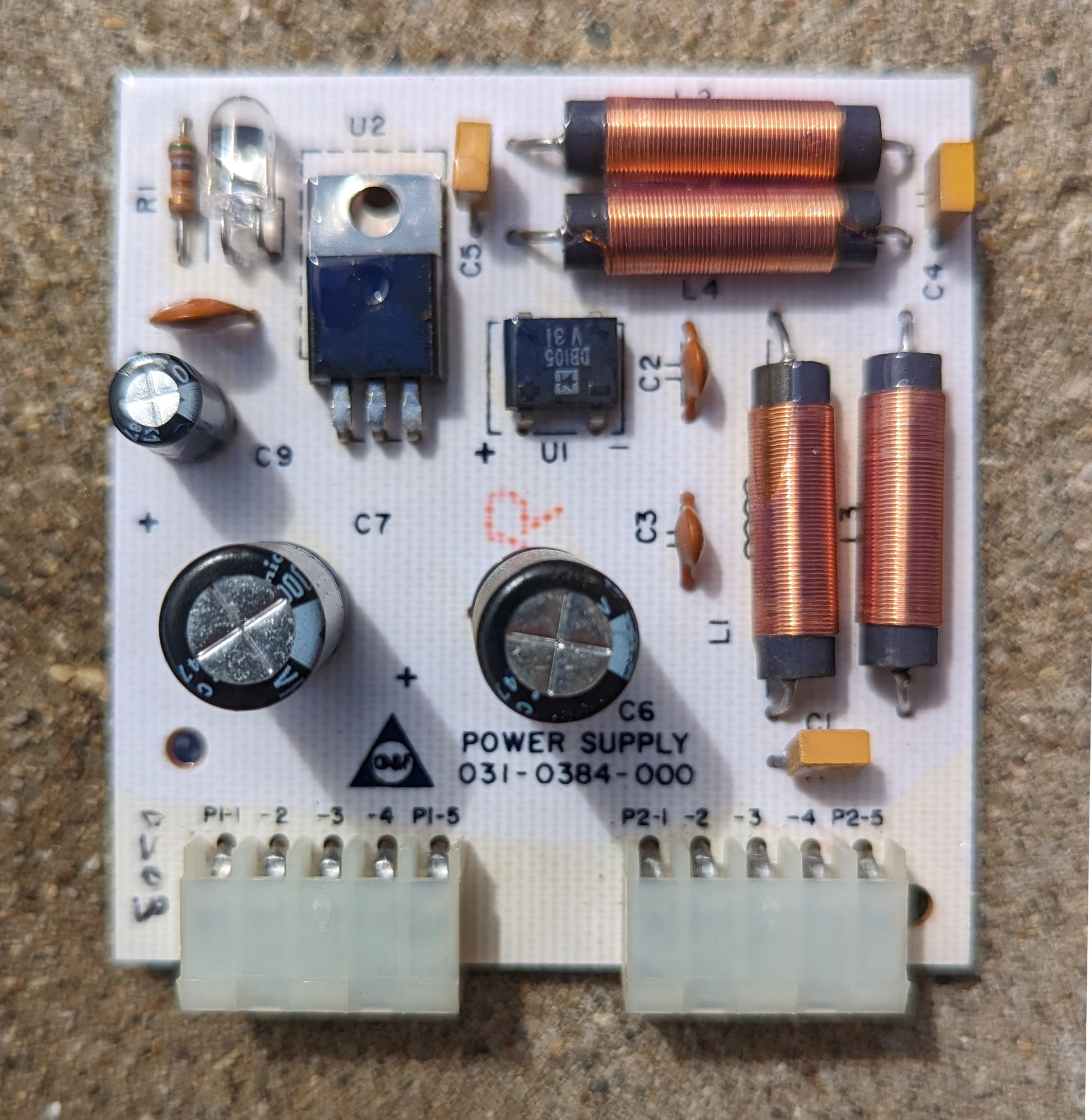
| 02:56, 23 May 2024 | Cdf SC psu module front.jpg (file) |  |
934 KB | Trevor229 | Front of the SC series CD&F power supply module | 1 |
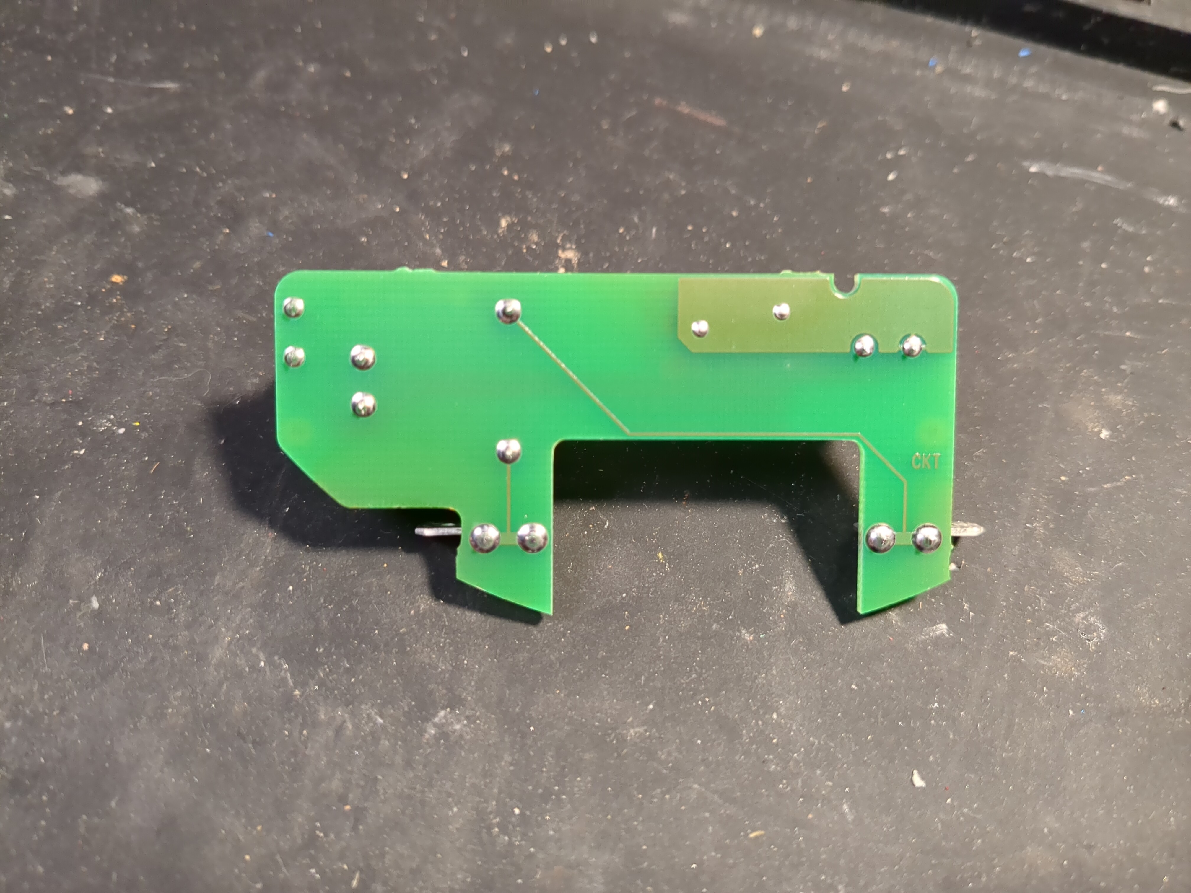
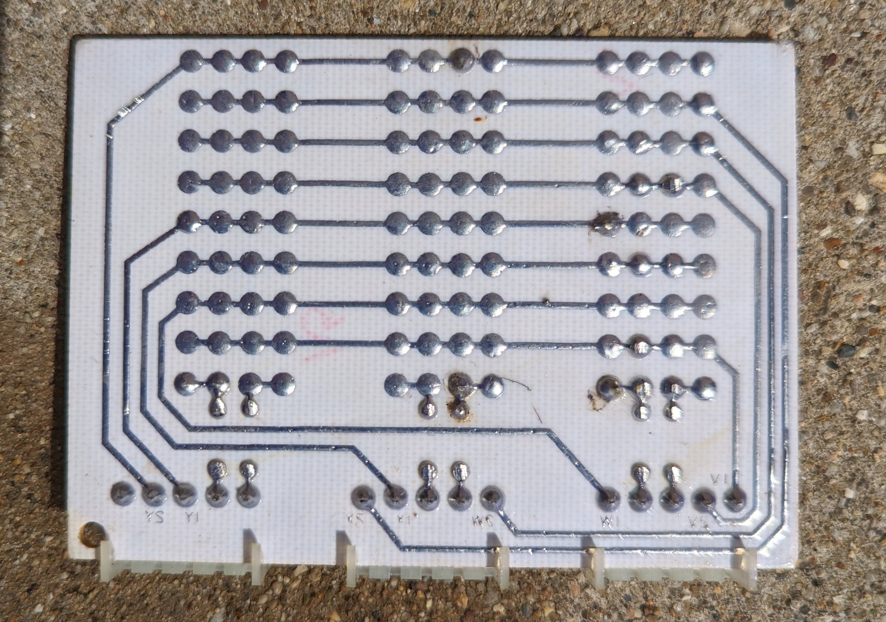
| 02:55, 23 May 2024 | Cdf SC psu back.jpg (file) |  |
843 KB | Trevor229 | Rear of the SC series CD&F power supply module | 1 |
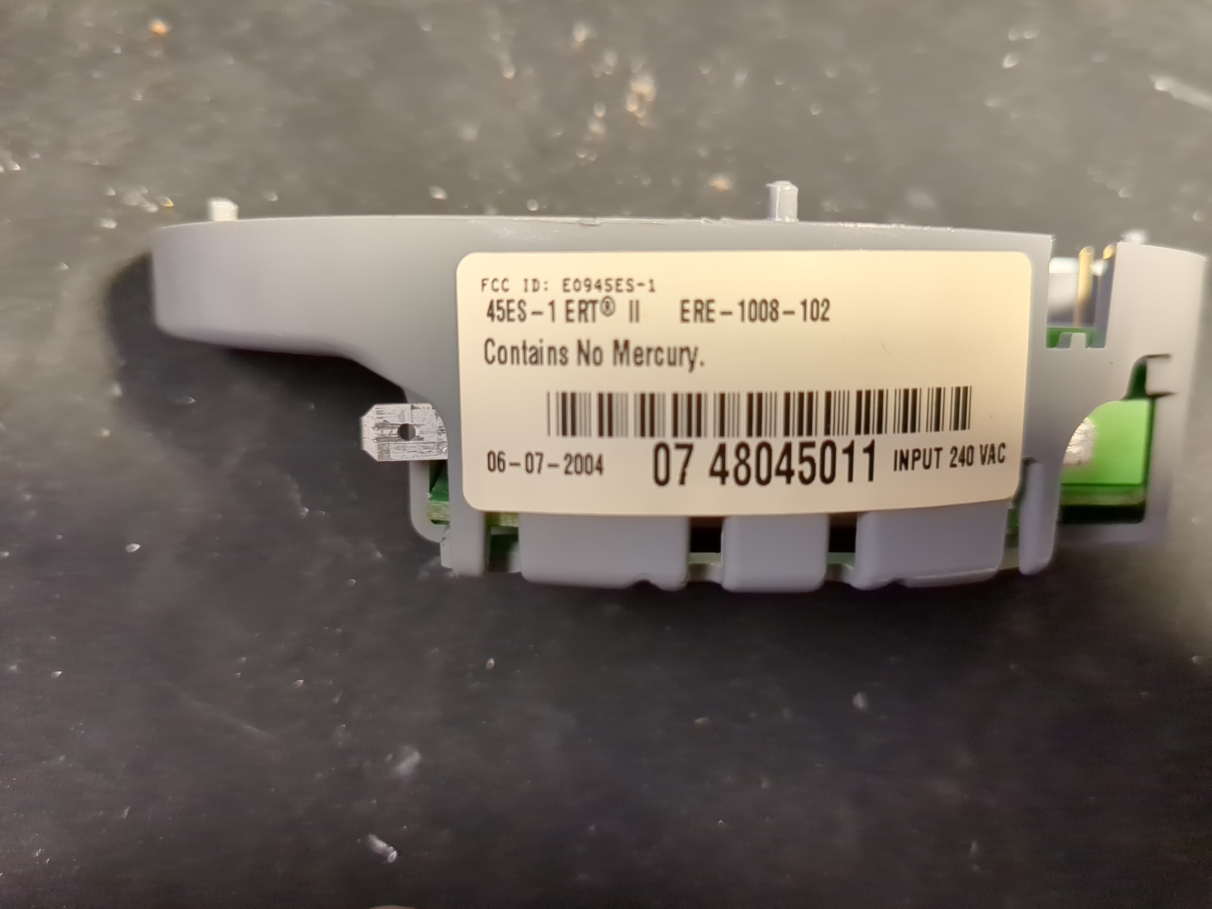
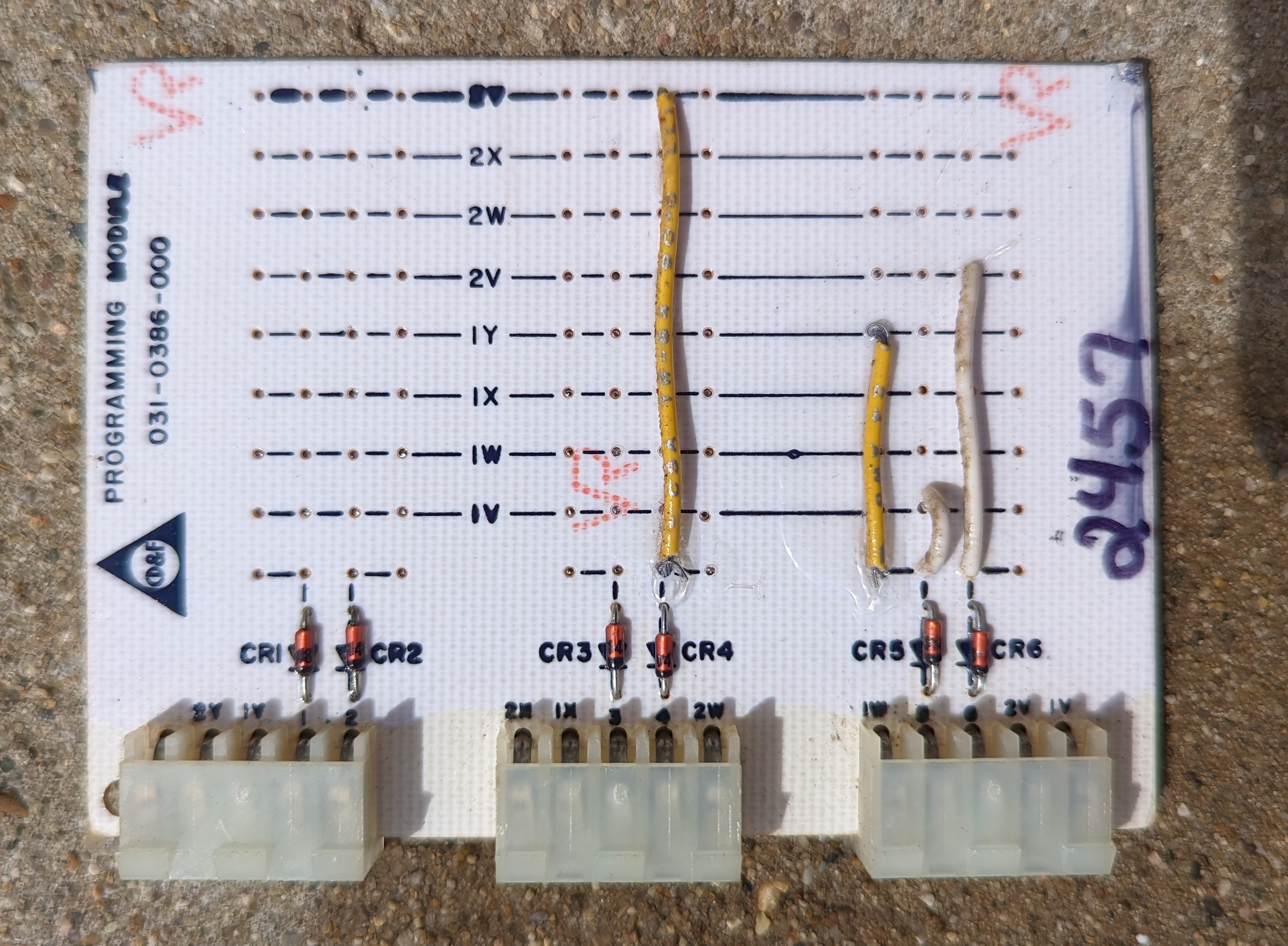
| 02:54, 23 May 2024 | Cdf SC prog module front.jpg (file) |  |
1.15 MB | Trevor229 | Front of the SC series CD&F programming module | 1 |
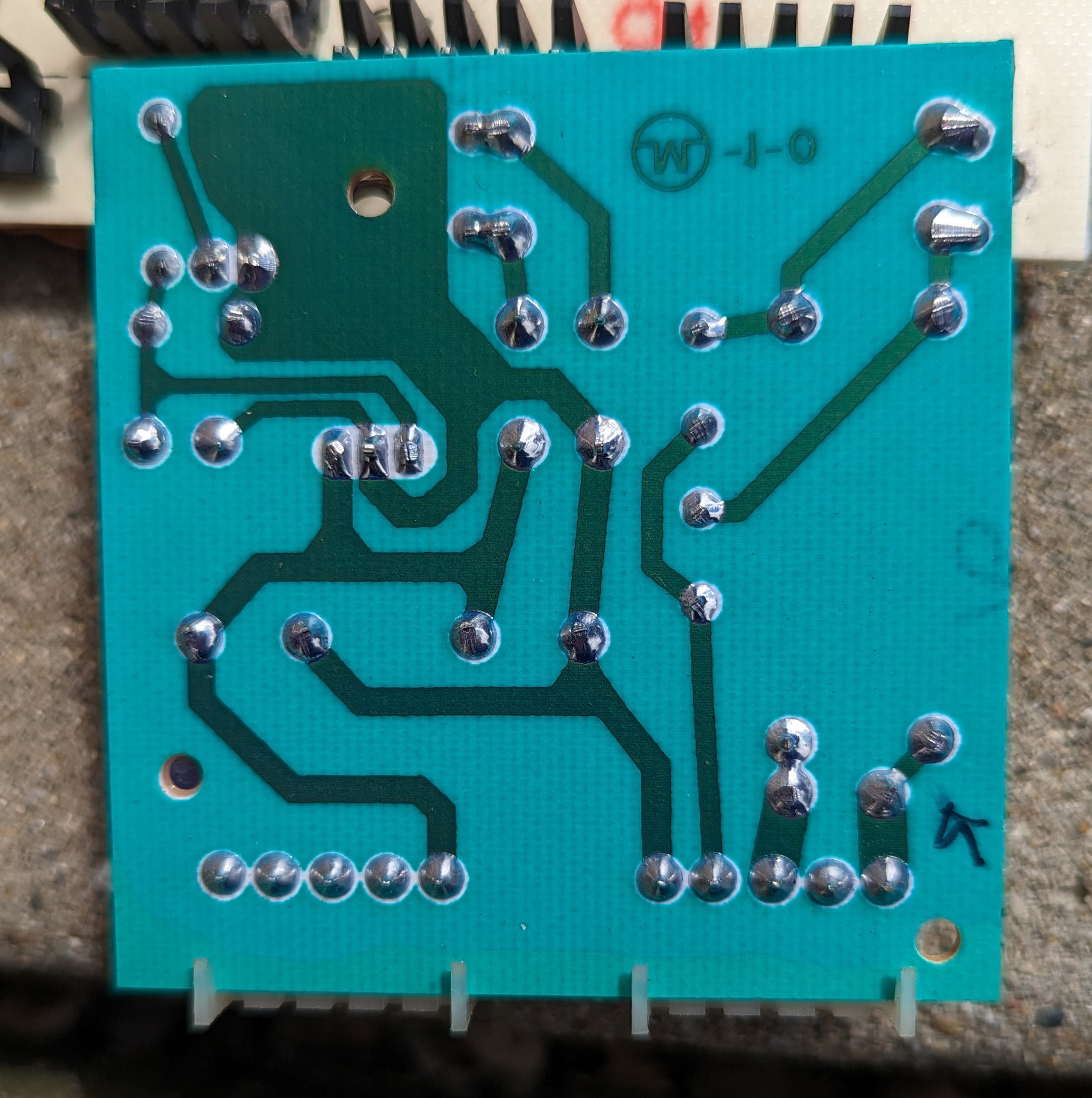
| 02:54, 23 May 2024 | Cdf SC prog module back.jpg (file) |  |
1.32 MB | Trevor229 | Rear of the SC series CD&F programming module | 1 |
| 02:53, 23 May 2024 | Cdf SC front case.jpg (file) |  |
1.09 MB | Trevor229 | Front case of my SC series unit before restoration. The logo was penciled in by me for measurement and recreation | 1 |