Yamaha EBike Battery Dongle
Contents
Yamaha Battery Emulator Dongle
Yamaha made a E-Bike Drive System called the PW series.
This research mainly focussed on Yamaha Engines, but also apply to some Giant Engines that have 3 pin Batteries since they are made by Yamaha aswell.
Later Giant engines uses 5 pin Batteries that utilize CAN-Bus (which internally gets converted to the Yamaha format in the engine itself.) dont work.
In order to connect a Third party Battery or any Voltage Source within the useable Voltage Range of a 10Cell in series Lithium-Ion battery (27 - 42V) the Battery needs to communicate with the Engine to be able to turn it on.
See this german pedelecforum thread for the original efforts and informations.
The Battery is quite sensitive to unauthorized power users. By default it is in its Low power mode.
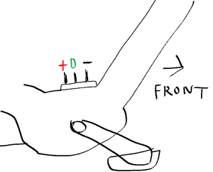
It will provide VBat at a very low current just to keep the Engine in standby and to allow for the Data pin to go high once pressing the Power button.
If you draw current from the Battery (like having a Lamp connected to it) it might trip its safety mechanism and goes into AFE Fault
This is a non recoverable (as of yet) fault that renders this expensive battery into a fancy brick.
By using this dongle its possible to replace the internal BMS with a generic one and fool the Engine to see a genuine battery, so it will turn on regardless.
When it sees 5V, it reports back to the Engine if everything is okay and if the High Power mode is enabled, if yes, the engine is allowed to Draw up to 30Amps.
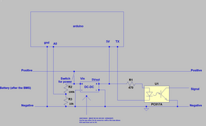
The battery sends data when the Bike-DATA pin has 5V on it, you can force it to send data by pulling it high with 470 ohm resistor.
To send data to the Bike, you gotta pull the DATA pin to Ground on each bit. Using a optocoupler is the best and easiest way as it also provides isolation in case the DC-DC converter goes south and applies 42V to the Data pin.
This might also happen if you drop your keys on the Contacts when removing the battery as the big storage capacitor holds a charge for quite some time.
If this happens, it becomes a annoying repair involving a tiny dual npn transistor. as seen here
Capturing Data for Analysis
After some Measurements with a Oscilloscope it turned out to be Serial communication at 2400 BAUD with 8 bits, even parity, 1 stop bit.
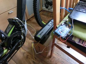
So a quick Arduino MEGA 2560 setup was used to Capture Data while driving from the Battery by hooking it to one of the Additional Hardware Serial ports and connecting a SD Card reader to it.
A basic sketch to append any incoming bytes into a Text file on the SD card was used. The Arduino was powered by a USB Power bank and two thin wires were wrapped around the Battery contacts.
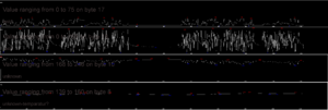
Some of the captured data of a 5.5km ride was visualized to see, what they could be
Thanks to User Tobi_36 and Cosas for figuring out Byte 16 and how the Checksum is calculated aswell as the Charging port Pinout
It transmits 19 bytes each 250ms. When the data makes no sense or is sent too slow, the Engine turns off after 4 Seconds and wont ever Unlock.
- B1 0xFF
- B2 0xFF
- B3 0xE
- B4 0x6
- B5 Battery fill in percent 0-100
- B6 0x10 or 0x19 unknown
- B7 temperature is °C = (( Byte7 x 256 ) + Byte8) x 0.05) negative temperature values are encoded by two's complement
- B8 see above
- B9 Voltage is V = ( ( Byte9 x 256)+ Byte10 ) * 0.05
- B10 see above
- B11 Battery capacity indicator 0x2A is 400Wh, 0x35 is 500Wh, 0x54 is 800Wh
- B12 allways 0xF8
- B13 allways 0x1
- B14 0x24 when no charger is connected, 0x0 when connected.
- B15 0x17
- B16 LEDs on the Battery, binary 1111 0000 is all 4 leds. 1100 0000 is only 2/4 leds.
- B17 Current is mA = (Byte17 x 256) + Byte18
- B18 see above
- B19 Checksum To calculate the Checksum this C code is needed
b19 = ((b1-b2-b3-b4-b5-b6-b7-b8-b9-b10-b11-b12-b13-b14-b15-b16-b17-b18)%256)+256;
With this, it was possible to recreate a valid datastream to fool the engine to turn on.
Fourtainly it doesnt check anything except Checksum and Battery percentage. you can basically send anything in Current, Temperature and Voltage. It doesnt care.
Results and Prototypes
Version 0.1 Proof of concept
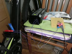
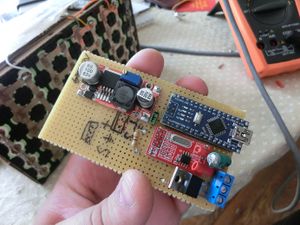
The arduino got powered over an LM2596HV DC-DC converter and i used a external 16bit ADC for Battery voltage measurement which later turned out to be not necessary.
To send data two transistors was used. One to invert the Serial signal, one to Pull down the DATA line while sending bits. It worked but was not a good choice for longer usecases.
Good enough for most, like the user alone109 using a plastic box filled with LiPo batteries as a range extender. apparently he made a few thousand kilometers with this setup.
My attempt wasnt that great. Im not a woodworker as you can see
Version 1
The V1 was a step up as it utilized a optocoupler for sending data, it was safer in case the dc-dc converter died and might have sent 42v into the data port.
The code for version 1.5 can be found here
Version 2
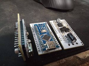
This version used a Arduino Mini on a daughterboard that contained all the DC-DC converter components and a optocoupler for pulling the DATA pin low. it was cheap and easy but not small.
It can be found on the OSHW Project site
Version 3
Going smaller ment to use different parts. The Atmega 328p used on the Arduino was way overkill too, it really needed to perform one task. So ive chosen a ATtiny 85 instead on a very small PCB
Unfourtainly it suffered the problem of being double sided. This greatly increased manufacturing costs.
A single sided version was needed.
Version 3.5
It was single sided but i was not satisfied with. Programming was hard as it was packed quite tight.
At least it could be manufactured for cheap at the usual chinese pcb fabs.
This project is available on the OSHW Project site
Version 4
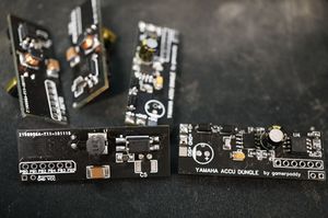
Same as 3.5 but not as tighly packed and now using different TCXO.
The Programming header ment easier programming with a jig.
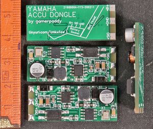
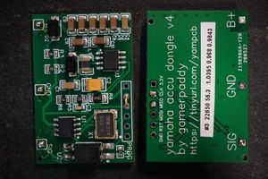
The picture contains version 4.0, the latest is 4.1 that doesnt require that jumperlink anymore.
This final version together with the required Arduino Code can be found on the OSHW Project page
The Code used for the latest dongle is as follows and is made for the Dongle specifically.
If you intent to use it for a different Chip and / or Board you might need to change the Pin and Port mappings.
The Attiny85 library i used didnt support SoftSerial so i bit-banged my own.
It is important to use a external TCXO. The Yamaha system is quite strict about timings, the internal oscialltor might drift when temperature changes and it stops working.
With a external TCXO you can ignore the Calibration section.
//calibration
#define SENDDELAY 198000 //delay between datasets. capture must be 164ms  https://i.imgur.com/LXj3fqW.png
#define BITTIME 490 // bit duration. adjust for start bit in 0xFF for 417µs length https://i.imgur.com/IWQ1Sz1.png
#define PARITYDELAY 0.97 //parity bit length modifier. capture must be 417µs https://i.imgur.com/W9EwHV5.png
#define BITDELAY 1.038 // bit length modifier. capture must be (0xFF, first 2 bits for reference) 3337µs https://i.imgur.com/xPBU9pW.png

//to check data, capture on pin PB0 and decode in saleae logic for Serial, 2400 BAUD, 8 bits, 1 stop bit, even parity. LSB, Non inverted, no special mode.


//default data. 100% 19.15°C 38V 400Wh 1024mA
byte data[] = {0xFF, 0xFF, 0x0E, 0x06,   0x64,   0x19,   0x01, 0x7F,   0x02, 0xF8,   0x2A,   0xF8, 0x01,   0x18, 0x11, 0xF0,   0x04, 0x00,   0x00};

void setup() {
  pinMode(0,OUTPUT); //TX
  analogReference(INTERNAL);
}

byte chksum() {
  int _t = data[0];
  for (char i = 17; i > 0; i--) {
    _t = _t - data[i];
  } return ((_t % 256) + 256);
}

//PORTB &= B11111110; // set pin 0 high
//PORTB |= B00000001; //set pin 0 low

const byte averages = 40;

void sendChar(char c){
  noInterrupts();
  delayMicroseconds(BITTIME);
  byte bits = 0;
  PORTB &= B11111110;
  delayMicroseconds(BITTIME);
   for (char i=0; i<8;i++){
     byte bitr = bitRead(c,i);
     if(bitr == 1){bits++;}
     if(bitr > 0){
      PORTB |= B00000001;
     }else{
      PORTB &= B11111110;
     }
     delayMicroseconds(BITTIME/BITDELAY);
   }
   if((bits % 2) == 0 && bits != 1){
    PORTB &= B11111110;
   }else{
    PORTB |= B00000001;
   }
   bits = 0;
   delayMicroseconds(BITTIME/PARITYDELAY);
   PORTB |= B00000001;
   interrupts();
}

long avg = 0;
int sample = 0;
byte ctr = 0;
char batt_percent = 100;
void loop() {
  delayMicroseconds(SENDDELAY);
  sample = analogRead(A1);
  if(sample>=900){sample=900;}
  if(sample<=720){sample=720;}
  //avg = (((avg<<2) - avg + sample) + 2) >> 2;
  avg = avg + sample;
  ctr++;
  if(ctr == averages){
      batt_percent = (char)map((avg/averages),720,900,0,100);
      ctr = 0;
      avg = 0;
  }

  if(batt_percent<=5){batt_percent=5;}
  if(batt_percent>=100){batt_percent=100;}

  data[4] = batt_percent;
  data[18] = chksum();

  for (char i = 0; i <= 18; i++) {
    sendChar(data[i]);
  }

}
Conclusion
With this project i may have saved a bunch of people a lot of money and gave them more freedom to do with their property what they want to do.
i rarely used my own work myself in the end, but i dont regret risking killing a newly bought ebike just to figure things out.
