Uncategorized files
Showing below up to 100 results in range #251 to #350.
View (previous 100 | next 100) (20 | 50 | 100 | 250 | 500)
 LandisGyr-Collector-Heatsinks-Cables.jpg 4,592 × 3,448; 7.07 MB
 LandisGyr-Collector-PWR-Bot-Pano.jpg 7,228 × 5,033; 22.93 MB
 LandisGyr-Collector-PWR-Top-Pano.jpg 6,826 × 4,756; 21.31 MB
 LandisGyr-Collector-PWR-Top-Transformer.JPG 2,152 × 1,686; 1.74 MB
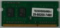
 LandisGyr-Collector-RAM-Bot.JPG 1,709 × 792; 783 KB
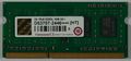
 LandisGyr-Collector-RAM-Top.JPG 1,718 × 796; 752 KB
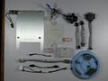
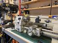
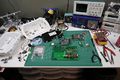 LandisGyr-Collector-Workbench-Overview.JPG 6,000 × 4,000; 13.44 MB
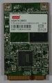 LandisGyr-Collector-mSATA-Bot.JPG 839 × 1,325; 726 KB
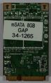 LandisGyr-Collector-mSATA-Top.JPG 806 × 1,314; 664 KB
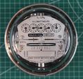 LandisGyrAnalogMeter.JPG 3,705 × 3,519; 7.03 MB
 LandisGyrCollector1.JPG 6,000 × 4,000; 9.06 MB
 LandisGyrCollector2.JPG 6,000 × 4,000; 9.13 MB
 LandisGyrCollector3.JPG 6,000 × 4,000; 12.5 MB
 LandisGyrCommercialMeter1.JPG 6,000 × 4,000; 9.22 MB
 LandisGyrCommercialMeter2.JPG 6,000 × 4,000; 10.84 MB
 LandisGyrCommercialMeter3.JPG 6,000 × 4,000; 11.09 MB
 LandisGyrResidentialMeter1.JPG 3,603 × 3,651; 5.55 MB
 LandisGyrResidentialMeter2.JPG 6,000 × 4,000; 9.77 MB
 LandisGyrResidentialMeter3.JPG 6,000 × 4,000; 9.31 MB
 LandisGyrWangateRadio1.JPG 6,000 × 4,000; 10.06 MB
 LandisGyrWangateRadio2.JPG 6,000 × 4,000; 10.44 MB
 LandisGyrWangateRadio3.JPG 6,000 × 4,000; 11.66 MB
 LandisGyrWangateRadio4.JPG 6,000 × 4,000; 12.44 MB
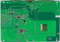
 LandisGyr PCBD-00106 Rev06 Bot.JPG 3,081 × 2,322; 3.46 MB
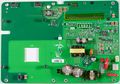
 LandisGyr PCBD-00106 Rev06 Top.JPG 3,111 × 2,312; 4.03 MB
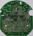
 LandisGyr PCB 24-1082 RevAE.JPG 3,252 × 3,370; 6.67 MB
 LandisGyr PCB 24-1082 RevAE Sand1.jpg 1,500 × 1,621; 263 KB
 LandisGyr PCB 24-1082 RevAE Sand2.jpg 2,984 × 3,230; 961 KB
 LandisGyr PCB 24-1082 RevAE Sand3.jpg 2,983 × 3,239; 1.25 MB
 LandisGyr PCB 24-1082 RevAE Sand4.jpg 2,986 × 3,237; 878 KB
 LandisGyr PCB 24-1562 RevAA.JPG 3,253 × 3,375; 2.78 MB
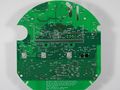
 LandisGyr PCB 24-2411 RevAC Bottom.JPG 3,163 × 3,369; 4.69 MB
 LandisGyr PCB 24-2411 RevAC JTAGSolderPoints.jpeg 2,370 × 1,680; 1.03 MB
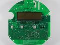
 LandisGyr PCB 24-2411 RevAC TopNoScreen.JPG 4,592 × 3,448; 7.31 MB
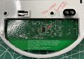
 LandisGyr PCB 24-2411 RevAC TopScreen.JPG 4,592 × 3,448; 6.81 MB
 LandisGyr PCB Blank1.JPG 3,136 × 3,358; 6.46 MB
 LandisGyr PCB Blank2.JPG 3,130 × 3,352; 5.62 MB
 LandisGyr PWB-72127 RevA Bot.JPG 3,733 × 2,329; 4.72 MB
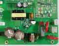
 LandisGyr PWB-72127 RevA Top.JPG 3,604 × 2,264; 3.67 MB
 Laser Camera-front.jpg 5,184 × 3,456; 1.52 MB
 Left side spudger insert pager.jpg 2,268 × 4,032; 1.79 MB
 MaLo2SN.png 706 × 194; 6 KB
 Mainboard back pager.jpg 4,032 × 2,268; 1.99 MB
 Mainboard front pager.jpg 4,032 × 2,268; 1.45 MB
 MasterMeter3G AntennaBack.JPG 4,592 × 3,448; 6.12 MB
 MasterMeter3G AntennaFront1.JPG 4,592 × 3,448; 7.4 MB
 MasterMeter3G AntennaFront2.JPG 4,592 × 3,448; 8.18 MB
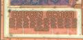 MasterMeter3G CC1100 logo.jpeg 2,570 × 1,239; 533 KB
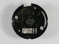 MasterMeter3G DialBottom.JPG 4,592 × 3,448; 4.28 MB
 MasterMeter3G DialTop.JPG 4,592 × 3,448; 5.33 MB
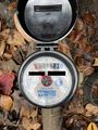 MasterMeter3G InstalledUnit.jpeg 1,574 × 2,100; 792 KB
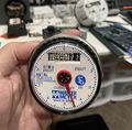 MasterMeter3G MeterInHand.jpeg 2,727 × 2,674; 1.78 MB
 MasterMeter3G PCBBottom.JPG 4,592 × 3,448; 6.63 MB
 MasterMeter3G PCBSide-antenna.jpeg 2,539 × 1,998; 1.09 MB
 MasterMeter3G PCBTop-antenna.jpeg 2,852 × 3,177; 2.05 MB
 MasterMeter3G PCBTop.JPG 4,592 × 3,448; 6.62 MB
 MasterMeter3G PCBTop2.JPG 4,592 × 3,448; 7.46 MB
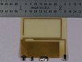
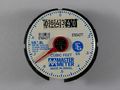
 MasterMeter3G TLMW301.jpg 1,600 × 1,200; 759 KB
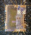 MasterMeter3G TLMW301 (CC1100).jpg 6,862 × 7,538; 40.52 MB
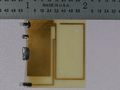
 MasterMeter3G TLMW301 (CC1100) small.jpg 6,862 × 7,538; 4.06 MB
 MasterMeter3G User-Manual.pdf ; 552 KB
 Maxon DIP switch config.png 751 × 897; 42 KB
 Maxon radio status chart.png 807 × 766; 60 KB
 Maxon sd 161.jpg 941 × 561; 204 KB
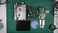
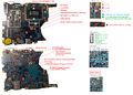 Mb breakdown.jpg 6,008 × 4,296; 4.12 MB
 Mechanic-UVH900-LY.jpg 2,000 × 598; 335 KB
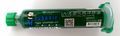
 Mechanic TY-V866.jpg 2,000 × 2,124; 970 KB
 Mechanical Tools.jpeg 4,032 × 3,024; 2.83 MB
 Menda35122.jpg 2,000 × 233; 77 KB
 Meter data capture.grc.txt ; 43 KB
 Metricom Utilinet IWR Series II - All Parts.jpg 3,840 × 2,160; 4.55 MB
 Metricom Utilinet IWR Series II - Case External.jpg 869 × 1,330; 530 KB
 Metricom Utilinet IWR Series II - Case Internal.jpg 3,840 × 2,160; 4.69 MB
 Metricom Utilinet IWR Series II - Processor Board.jpg 5,022 × 3,416; 12.12 MB
 Metricom Utilinet IWR Series II - RF Board.jpg 4,730 × 3,260; 9.72 MB
 MiJingT26.jpg 2,000 × 1,416; 636 KB
 Mini 4g router pcb bottom.jpg 400 × 137; 65 KB
 Modified DFM-17 Radiosonde.jpg 2,900 × 1,642; 1.3 MB
 Modify password menu.jpg 4,032 × 2,268; 1.66 MB
 Module Base-bottom.jpg 5,184 × 3,456; 1.26 MB
 Module Base-top.jpg 5,184 × 3,456; 1.85 MB
 Motorola Flip Phone.jpg 768 × 1,024; 218 KB
 Neato WiFi Controller attached.jpg 4,128 × 3,096; 3.11 MB
 Neato WiFi PCB Power.jpg 4,128 × 3,096; 1.6 MB
 Neato WiFi adaptor schematic.jpg 1,228 × 665; 162 KB
 Neato Wifi Adaptor install.jpg 4,128 × 3,096; 1.83 MB
 Neato Wifi Adaptor solder points.jpg 1,119 × 842; 717 KB
 Neato Wifi Dremel Modification.jpg 3,096 × 4,128; 1.85 MB
 Neato XV-11.jpg 893 × 578; 31 KB
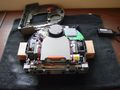 Neato XV-11 Disassembled.jpg 1,600 × 1,200; 382 KB
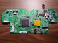 Neato XV-11 Early PCB Version.jpg 2,272 × 1,704; 1.03 MB
 Neato XV-11 Folders of CD.jpg 399 × 246; 37 KB
 Neato XV-11 LCD Board.zip ; 40 KB
 Neato XV-11 LCD panel back labels.png 749 × 498; 454 KB
 Neato XV-11 LCD panel front labels.png 560 × 495; 352 KB
 Neato XV-11 Map bathroom1-laser.gif 512 × 512; 794 KB
 Neato XV-11 Map bathroom1.gif 256 × 256; 923 KB
 Neato XV-11 Map bathroom2.gif 256 × 256; 1.2 MB
 Neato XV-11 Map capture-laser.gif 512 × 512; 202 KB
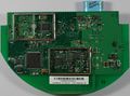
 Neato XV-11 PCB Rev64 Bottom.jpg 4,846 × 2,436; 4.57 MB


.jpg)
_small.jpg)


