Uncategorized files
Jump to navigation
Jump to search
Showing below up to 250 results in range #51 to #300.
View (previous 250 | next 250) (20 | 50 | 100 | 250 | 500)
 Back laid flat pager.jpg 4,032 × 2,268; 1.7 MB
 Back pager.jpg 1,560 × 878; 499 KB
 Basic Tools.jpg 3,897 × 2,781; 4.09 MB
 Baud menu.jpg 4,032 × 2,268; 1.7 MB
 Bearing Motor-side.jpg 5,184 × 3,456; 1.64 MB
 Belt Shield-top.jpg 2,374 × 2,576; 1.63 MB
 BigSpoon.JPG 2,000 × 1,286; 708 KB
 Blink syncmodule2 photo1.jpg 1,728 × 1,728; 778 KB
 Bottom layer zoom.jpg 5,776 × 5,824; 19.38 MB
 Bst-y22.jpg 5,824 × 843; 2.75 MB
 Bst-y23.jpg 6,016 × 827; 2.7 MB
 C-mount-spacer.JPG 1,464 × 1,040; 361 KB
 CAD View.zip ; 688 KB
 CLS-HAN.png 736 × 540; 210 KB
 Camera focus.JPG 2,140 × 1,640; 1.06 MB
 Canon-powershot-g9.jpg 355 × 241; 14 KB
 Canon PowerShot A3100 IS.jpg 369 × 307; 39 KB
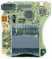
 Canon PowerShot A3100 IS Main Back.jpg 2,064 × 1,753; 738 KB
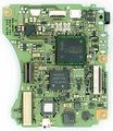
 Canon PowerShot A3100 IS Main Front.jpg 2,039 × 1,705; 788 KB
 Canon PowerShot A3100 IS buttons back.jpg 2,595 × 854; 351 KB
 Canon PowerShot A3100 IS buttons front.jpg 2,605 × 883; 407 KB
 Canon PowerShot A3100 IS ccd front.jpg 5,342 × 2,063; 1.07 MB
 Canon PowerShot A3100 IS ccd sensor back.jpg 3,378 × 2,500; 1.27 MB
 Canon PowerShot A3100 IS debug connector.jpg 588 × 467; 80 KB
 Canon PowerShot A3100 IS sd back.jpg 2,391 × 1,976; 281 KB
 Canon PowerShot A3100 IS sd card front.jpg 2,335 × 2,028; 824 KB
 Canon PowerShot G9 Back Camera Control PCB.jpg 1,857 × 2,898; 1.14 MB
 Canon PowerShot G9 IC502.jpg 2,000 × 1,929; 449 KB
 Canon PowerShot G9 Main PCB Assembly Diagram.png 2,120 × 1,167; 478 KB
 Canon PowerShot G9 Main PCB Back.jpg 2,327 × 2,633; 1.58 MB
 Canon PowerShot G9 Main PCB Top.jpg 2,323 × 2,679; 1.72 MB
 Canon PowerShot G9 Power PCB Top.jpg 2,589 × 1,772; 947 KB
 Canon PowerShot G9 Power PCB bottom.jpg 2,572 × 1,753; 830 KB
 Canon PowerShot G9 Top Controls FPC.jpg 1,888 × 2,945; 919 KB
 Canon PowerShot G9 debug header.jpg 428 × 602; 95 KB
 Canon PowerShot G9 image sensor.jpg 4,699 × 2,216; 1 MB
 Capcode menu.jpg 4,032 × 2,268; 1.66 MB
 Cdf back.jpg 2,263 × 2,975; 1,002 KB
 Cdf bare mainboard.jpg 2,255 × 2,805; 1.96 MB
 Cdf bare mainboard back.jpg 2,146 × 2,756; 1.48 MB
 Cdf bottom.jpg 4,032 × 2,268; 1.68 MB
 Cdf cycle timer back.jpg 3,129 × 2,235; 1.91 MB
 Cdf cycle timer front.jpg 4,032 × 2,268; 2.58 MB
 Cdf decoder module a back.jpg 3,141 × 2,121; 1.67 MB
 Cdf decoder module a front.jpg 2,833 × 2,259; 1.94 MB
 Cdf filters bottom.jpg 2,268 × 4,032; 2.29 MB
 Cdf filters top.jpg 2,268 × 4,032; 2.31 MB
 Cdf front closed.jpg 2,268 × 4,032; 1.03 MB
 Cdf front open.jpg 2,264 × 3,496; 2.28 MB
 Cdf hinge side.jpg 2,268 × 4,032; 1.24 MB
 Cdf info onboard.jpg 4,032 × 2,268; 1.79 MB
 Cdf latch side.jpg 2,268 × 4,032; 1.2 MB
 Cdf mod power connections.jpg 878 × 1,560; 364 KB
 Cdf modded LO.jpg 517 × 919; 98 KB
 Cdf relay driver back.jpg 2,268 × 2,070; 1.17 MB
 Cdf relay driver schematic.png 1,169 × 827; 53 KB
 Cdf relay driver top.jpg 2,251 × 2,001; 1.32 MB
 Cdf rx closeup.jpg 4,032 × 2,268; 1.94 MB
 Cdf rx closeup back.jpg 4,032 × 2,268; 2.15 MB
 Cdf si5351 test.jpg 517 × 919; 123 KB
 Cdf terminals closeup.jpg 4,032 × 2,268; 1.62 MB
 Cdf timer RC scope.png 800 × 480; 26 KB
 Cdf timer rc scope2.png 800 × 480; 17 KB
 Cdf tone info.jpg 4,032 × 2,268; 1.46 MB
 Cdf top.jpg 4,032 × 2,268; 1.18 MB
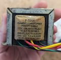 Cdf xfmr pri.jpg 2,259 × 2,249; 1.18 MB
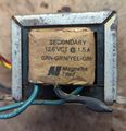 Cdf xfmr sec.jpg 2,267 × 2,337; 1.3 MB
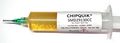 Chipquik SMD29130CC rev1.jpg 2,000 × 717; 209 KB
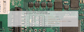
 Closeup circuitry pager.jpg 4,032 × 2,268; 1.94 MB
 Completely free back pager.jpg 4,032 × 2,268; 1.71 MB
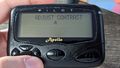 Contrast menu.jpg 4,032 × 2,268; 1.71 MB
 Correctly snapped left pager.jpg 1,560 × 878; 138 KB
 DFM-17 Battery Holder.jpg 6,026 × 4,024; 23.83 MB
 DFM-17 Internal.jpg 5,458 × 3,251; 20.93 MB
 DFM-17 NOAA Label.jpg 503 × 890; 103 KB
 DFM-17 Radiosonde in hand.jpg 668 × 891; 100 KB
 DFM-17 SWD Port pinout.png 1,139 × 434; 1.21 MB
 DFM-17 Uref overlay.jpg 5,458 × 3,251; 19.55 MB
- Error creating thumbnail: File with dimensions greater than 12.5 MPDFM-17 Uref overlayl.png 5,458 × 3,251; 46.9 MB
- Dallas-Wardrive-GPS uptime.zip ; 97 KB
 De-Potted Topping D01 Module.jpg 1,500 × 1,000; 388 KB
 Dfm17-2layers.png 4,466 × 2,721; 21.56 MB
 Dfm 17 swd and resistors.jpg 4,032 × 2,268; 2.43 MB
 Dfm back pcb no battery.jpg 3,023 × 1,873; 1.23 MB
 Discord-Logo-Color.png 245 × 240; 2 KB
 Discord-Logo-Color.svg 512 × 502; 1 KB
 Disney Flix Camcorder.jpg 500 × 500; 41 KB
 Disney Flix Camcorder Construction.jpg 2,048 × 1,365; 281 KB
 Disney Flix Camcorder Controls PCB Back.jpg 4,234 × 1,335; 970 KB
 Disney Flix Camcorder Controls PCB front.jpg 4,178 × 1,466; 1.21 MB
 Disney Flix Camcorder Display PCB back.jpg 1,853 × 1,766; 734 KB
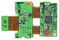
 Disney Flix Camcorder Main PCB Front.jpg 2,323 × 2,784; 1.57 MB
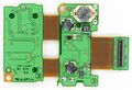
 Disney Flix Camcorder Main PCB back.jpg 2,311 × 2,749; 1.58 MB
 Disney Flix Camcorder Sensor PCB Front.jpg 2,878 × 2,284; 1,016 KB
 Disney Flix Sensor PCB back.jpg 1,370 × 2,294; 819 KB
 ESS Schedule.png 1,218 × 666; 109 KB
 Edding8400.jpg 2,000 × 557; 226 KB
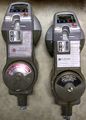 Electronic Parking Meter.jpg 2,006 × 2,802; 1.17 MB
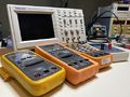 Electronic Tools.jpeg 4,032 × 3,024; 2.3 MB
 F03B9FFB.txt ; 629 KB
- F103-analysis-master.zip ; 27.14 MB
 FL101.png 453 × 463; 36 KB
 FL101 test setup.jpg 617 × 463; 74 KB
 Fan 1.jpg 2,664 × 2,605; 1.55 MB
 FlashlightPIN.png 1,575 × 517; 1.25 MB
 Frequency menu.jpg 4,032 × 2,268; 1.53 MB
 Front pager.jpg 1,560 × 878; 428 KB
 GE Model 8131-4A.jpg 1,280 × 720; 113 KB
 GE Model 8131-4A clock parts.jpg 3,929 × 2,946; 4.44 MB
 GoodWatch and PCB.jpg 3,712 × 3,358; 5.57 MB
 Grc on wsl.jpg 1,352 × 852; 123 KB
 HackingTheXbox Free.pdf ; 17.76 MB
 Hacktheplanet pager.jpg 747 × 520; 165 KB
 Hashs GoodWatch.jpg 1,688 × 1,438; 371 KB
 Headband magnifier.jpg 4,032 × 3,024; 4 MB
 ISKRAMT174.png 963 × 1,215; 541 KB
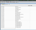 ISKRA LOG.png 1,746 × 1,469; 941 KB
 Inductors.jpg 2,387 × 2,188; 1.41 MB
 Insert spudger right side pager.jpg 4,032 × 2,268; 1.71 MB
 Itron Centron - B2B 1.JPG 3,840 × 2,160; 4 MB
 Itron Centron - B2B 2.JPG 3,840 × 2,160; 3.04 MB
 Itron Centron - B2B 3.JPG 3,840 × 2,160; 4.08 MB
 Itron Centron - B2B 4.JPG 3,840 × 2,160; 2.67 MB
 Itron Centron - B2B 5.JPG 3,840 × 2,160; 2.65 MB
 Itron Centron - Base 1.JPG 3,840 × 2,160; 4.75 MB
 Itron Centron - Base 2.JPG 3,840 × 2,160; 4.66 MB
 Itron Centron - Base Top 1.JPG 3,840 × 2,160; 4.81 MB
 Itron Centron - Base Top 2.JPG 3,840 × 2,160; 4.86 MB
 Itron Centron - Base Top 3.JPG 3,840 × 2,160; 4.62 MB
 Itron Centron - Base Top 4.JPG 3,840 × 2,160; 4.97 MB
 Itron Centron - Conn Term 1.JPG 3,840 × 2,160; 3.23 MB
 Itron Centron - Conn Term 2.JPG 3,840 × 2,160; 2.65 MB
 Itron Centron - Conn Term 3.JPG 3,840 × 2,160; 3.21 MB
 Itron Centron - Conn Term 4.JPG 3,840 × 2,160; 2.22 MB
 Itron Centron - Cover 1.JPG 3,840 × 2,160; 4.43 MB
 Itron Centron - Cover 2.JPG 3,840 × 2,160; 5.06 MB
 Itron Centron - LCD 1.JPG 3,840 × 2,160; 4.83 MB
 Itron Centron - LCD 2.JPG 3,840 × 2,160; 4.57 MB
 Itron Centron - Magnetic Core 1.JPG 3,840 × 2,160; 3.65 MB
 Itron Centron - Magnetic Core 2.JPG 3,840 × 2,160; 3.48 MB
 Itron Centron - Magnetic Core 3.JPG 3,840 × 2,160; 2.83 MB
 Itron Centron - Metrology 1.JPG 3,840 × 2,160; 4.67 MB
 Itron Centron - Metrology 2.JPG 3,840 × 2,160; 4 MB
 Itron Centron - Personality C1SR 1.JPG 3,840 × 2,160; 4.83 MB
 Itron Centron - Personality C1SR 2.JPG 3,840 × 2,160; 4.17 MB
 Itron Centron - Personality C1SR Assy 1.JPG 3,840 × 2,160; 3.54 MB
 Itron Centron - Personality C1SR Assy 2.JPG 3,840 × 2,160; 4.37 MB
 Itron Centron - Personality C1SR Cover 1.JPG 3,840 × 2,160; 3.95 MB
 Itron Centron - Personality C1SR Cover 2.JPG 3,840 × 2,160; 4.25 MB
 JTAGulator and Kenwood TH-D74.jpg 4,032 × 3,024; 2.88 MB
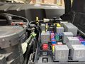 Jeep Fuses.jpg 4,032 × 3,024; 2.34 MB
 Jonard WSU-30M.jpg 2,000 × 312; 111 KB
- KDT2.0.zip ; 1.14 MB
 Kek-solderpaste-bot.jpg 2,000 × 961; 313 KB
 Kenwood TH-D74 Control Board Boot Pins.jpeg 2,303 × 1,729; 1.01 MB
 Kenwood TH-D74 and JTAGulator.jpg 1,024 × 768; 277 KB
 Knipex1240200.jpg 2,000 × 1,045; 439 KB
 Knipex1262180.jpg 2,000 × 1,550; 417 KB
 Knipex7001110.jpg 2,000 × 1,012; 221 KB
 Knipex927877ESD.jpg 2,000 × 325; 116 KB
 Knipex 7803125.JPG 2,000 × 1,347; 1.39 MB
 Kobalt LI Ion Charger 1.jpg 434 × 749; 81 KB
 Kobalt LI Ion Charger 2.jpg 519 × 767; 56 KB
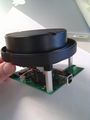 LIDAR mounted on PCB.jpg 1,944 × 2,592; 790 KB
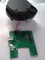 LIDAR plugged in to Interface board.jpg 1,944 × 2,592; 734 KB
 LMN Stack.png 650 × 505; 167 KB
 LMS-6 RH Sensor.svg 1,052 × 744; 128 KB
 LMS-6 Radiosonde.jpg 1,728 × 2,304; 4.15 MB
 LMS6.png 1,122 × 793; 42 KB
 LMS6 TX Path Schematic.svg 1,052 × 744; 140 KB
 LMS6 bottom.jpg 2,439 × 1,868; 940 KB
 LMS6 output lpf 200M-1425M.png 479 × 463; 37 KB
 LNMHANWAN.png 686 × 386; 110 KB
 Lab Bench Hardware Exploit.jpg 3,840 × 2,160; 2.07 MB
 Label id speculaton.jpg 2,729 × 1,626; 3.16 MB
- LandingVideo-1.mp4 ; 23.49 MB
- LandingVideo-2.mp4 ; 16.34 MB
 LandisGyr-Collector-Battery-Bot.JPG 3,291 × 2,366; 1.92 MB
 LandisGyr-Collector-Battery-Top.JPG 3,355 × 2,349; 2.22 MB
 LandisGyr-Collector-CPU-Bot.JPG 2,392 × 2,691; 3.85 MB
 LandisGyr-Collector-CPU-Top.JPG 2,488 × 2,665; 3.54 MB
 LandisGyr-Collector-Case-External-Bot.JPG 3,690 × 2,902; 3.29 MB
 LandisGyr-Collector-Case-External-Top.JPG 4,592 × 3,448; 4.74 MB
 LandisGyr-Collector-Case-Internal-Bot.JPG 4,592 × 3,448; 5.26 MB
 LandisGyr-Collector-Case-Internal-Top.JPG 4,592 × 3,448; 5.03 MB
 LandisGyr-Collector-Cellnet-Bot.JPG 2,824 × 3,329; 4.34 MB
 LandisGyr-Collector-Cellnet-Lid-Top.JPG 2,588 × 3,337; 4.65 MB
 LandisGyr-Collector-Cellnet-Top.JPG 2,668 × 3,344; 4.57 MB
 LandisGyr-Collector-Cellular-Bot.JPG 2,094 × 1,005; 1.01 MB
 LandisGyr-Collector-Cellular-Top.JPG 2,072 × 946; 1.17 MB
 LandisGyr-Collector-Heatsinks-Cables.jpg 4,592 × 3,448; 7.07 MB
 LandisGyr-Collector-PWR-Bot-Pano.jpg 7,228 × 5,033; 22.93 MB
 LandisGyr-Collector-PWR-Top-Pano.jpg 6,826 × 4,756; 21.31 MB
 LandisGyr-Collector-PWR-Top-Transformer.JPG 2,152 × 1,686; 1.74 MB
 LandisGyr-Collector-RAM-Bot.JPG 1,709 × 792; 783 KB
 LandisGyr-Collector-RAM-Top.JPG 1,718 × 796; 752 KB
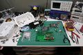 LandisGyr-Collector-Workbench-Overview.JPG 6,000 × 4,000; 13.44 MB
 LandisGyr-Collector-mSATA-Bot.JPG 839 × 1,325; 726 KB
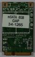 LandisGyr-Collector-mSATA-Top.JPG 806 × 1,314; 664 KB
 LandisGyrAnalogMeter.JPG 3,705 × 3,519; 7.03 MB
 LandisGyrCollector1.JPG 6,000 × 4,000; 9.06 MB
 LandisGyrCollector2.JPG 6,000 × 4,000; 9.13 MB
 LandisGyrCollector3.JPG 6,000 × 4,000; 12.5 MB
 LandisGyrCommercialMeter1.JPG 6,000 × 4,000; 9.22 MB
 LandisGyrCommercialMeter2.JPG 6,000 × 4,000; 10.84 MB
 LandisGyrCommercialMeter3.JPG 6,000 × 4,000; 11.09 MB
 LandisGyrResidentialMeter1.JPG 3,603 × 3,651; 5.55 MB
 LandisGyrResidentialMeter2.JPG 6,000 × 4,000; 9.77 MB
 LandisGyrResidentialMeter3.JPG 6,000 × 4,000; 9.31 MB
 LandisGyrWangateRadio1.JPG 6,000 × 4,000; 10.06 MB
 LandisGyrWangateRadio2.JPG 6,000 × 4,000; 10.44 MB
 LandisGyrWangateRadio3.JPG 6,000 × 4,000; 11.66 MB
 LandisGyrWangateRadio4.JPG 6,000 × 4,000; 12.44 MB
 LandisGyr PCBD-00106 Rev06 Bot.JPG 3,081 × 2,322; 3.46 MB
 LandisGyr PCBD-00106 Rev06 Top.JPG 3,111 × 2,312; 4.03 MB
 LandisGyr PCB 24-1082 RevAE.JPG 3,252 × 3,370; 6.67 MB
 LandisGyr PCB 24-1082 RevAE Sand1.jpg 1,500 × 1,621; 263 KB
 LandisGyr PCB 24-1082 RevAE Sand2.jpg 2,984 × 3,230; 961 KB
 LandisGyr PCB 24-1082 RevAE Sand3.jpg 2,983 × 3,239; 1.25 MB
 LandisGyr PCB 24-1082 RevAE Sand4.jpg 2,986 × 3,237; 878 KB
 LandisGyr PCB 24-1562 RevAA.JPG 3,253 × 3,375; 2.78 MB
 LandisGyr PCB 24-2411 RevAC Bottom.JPG 3,163 × 3,369; 4.69 MB
 LandisGyr PCB 24-2411 RevAC JTAGSolderPoints.jpeg 2,370 × 1,680; 1.03 MB
 LandisGyr PCB 24-2411 RevAC TopNoScreen.JPG 4,592 × 3,448; 7.31 MB
 LandisGyr PCB 24-2411 RevAC TopScreen.JPG 4,592 × 3,448; 6.81 MB
 LandisGyr PCB Blank1.JPG 3,136 × 3,358; 6.46 MB
 LandisGyr PCB Blank2.JPG 3,130 × 3,352; 5.62 MB
 LandisGyr PWB-72127 RevA Bot.JPG 3,733 × 2,329; 4.72 MB
 LandisGyr PWB-72127 RevA Top.JPG 3,604 × 2,264; 3.67 MB
 Laser Camera-front.jpg 5,184 × 3,456; 1.52 MB
 Left side spudger insert pager.jpg 2,268 × 4,032; 1.79 MB
 MaLo2SN.png 706 × 194; 6 KB
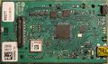
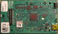
 Mainboard back pager.jpg 4,032 × 2,268; 1.99 MB
 Mainboard front pager.jpg 4,032 × 2,268; 1.45 MB
 MasterMeter3G AntennaBack.JPG 4,592 × 3,448; 6.12 MB
 MasterMeter3G AntennaFront1.JPG 4,592 × 3,448; 7.4 MB
 MasterMeter3G AntennaFront2.JPG 4,592 × 3,448; 8.18 MB
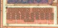 MasterMeter3G CC1100 logo.jpeg 2,570 × 1,239; 533 KB
 MasterMeter3G DialBottom.JPG 4,592 × 3,448; 4.28 MB
 MasterMeter3G DialTop.JPG 4,592 × 3,448; 5.33 MB
 MasterMeter3G InstalledUnit.jpeg 1,574 × 2,100; 792 KB
 MasterMeter3G MeterInHand.jpeg 2,727 × 2,674; 1.78 MB


,_John_W._Evans,_Jillian_Y._Evans_(eds.)_-_Product_Integrity_and_Reliability_in_Design-Springer-Verlag_London_(2001).jpg)


