Kobalt KRC 40-06
Background
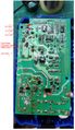
A lightning bolt hit a pole near my house and I lost several electronic items. One of them was my Kobalt KRC 40-06 that recharges the battery for my Kobalt (Lowes) string trimmer and leaf blower. Rather than throw it in the landfill and buy another, I decided to repair it and return it to action. It was easier said than done, but I was successful. The circuits are not too complex. The broad-stroke overview of the circuit is 120VAC is applied through a fuse, filtering, a common-mode choke, and a full-wave bridge rectifier, where it is converted to 172 VDC. The voltage is applied to the TOP386EG switcher that applies its voltage to the transformer. On the output side of the transformer, AC is then rectified through the MBR2560CT as well as applied to the logic monitoring the voltages and charge levels. The LTV-817B optocoupler provides feedback that controls the drive of the TOP386EG.
The voltage levels were taken with no load. In other words, the charger was not charging a battery.
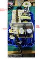
The board has a considerable amount of RTV applied and the component side is conformal coated.
“I really like your soldering”, said no one, ever! So feel free to ridicule my soldering. In my defense, the pictures were taken prior to clean up of the board. If nothing else, the pictures will provide comedic relief. Honestly, looking at this pictures makes me want to break out Q-Tips and rubbing alcohol. Trust me, the board was cleaned up and re-conformal coated.
Needed Tools
- 3mm or 7/64ths hex head driver
- Multimeter. Knowing how the diode function differs from the resistance function of the meter is helpful.
- X-Acto knife (or similar) to scrape through the conformal coating
- Soldering iron with flux and solder. Having two irons is helpful when removing surface mount devices (SMD)
Disassembly
With a flat-blade screwdriver, remove the rubber feet. This reveals 3mm/7-64th hex head screws. Remove them. The bottom should be able to to be separated from the unit to reveal the printed circuit board (PCB). The PCB is pressure fit in to the house and should be able to be removed.
Troubleshooting
If the input fuse has blown, the problem is probably in the input side. Perhaps the 180 uF/250V capacitor shorted. Perhaps the inductor, bridge rectifier diode pack shorted.
**WARNING**
120 VAC and up to 175 volts DC are present on the input side of the charger circuit. Under a bad set of circumstances, this could be lethal.
- Proceed at your own risk!*
If you're comfortable proceeding, then plug in to AC power. With the multimeter, look for the DC voltages indicated in the pictures.
Autopsy
Judging by the failed components, here is a guess as how my charger failed:
My house did not take a direct hit from the lightning bolt. If so, I’d have visible damage and many more items would have been destroyed. The charger was in the garage. My guess is the plasma field of the lightning caused the MBR2560CT to internally short. This caused maximum drive current to be sourced by the TOP368EG on the input side. Diode US1M on the right side of the picture was replaced as a part of the troubleshooting effort, but was probably good. The 3.15 amp input fuse did not blow and is still functioning. Perhaps yours failed in a similar manner.
All of the parts are available from Mouser https://www.mouser.com/
Kobalt Charger KRC 40-06 Underside
Kobalt Charger KRC 40-06 Topside

