Toyota Paseo GT 1.5 odometer Starlet P9 mod
Modification Overview
Modding guide on how to make the Toyota Paseo 1.5 GT (5E-FE 1995-1999) odometer plug and play "oem-clean" for the Toyota P9 (EP91 4E-FE 1996-1999).
This mod has the focus on not messing with the car wiring by depinning and changing the OEM wiring, but by modifying the GT cluster.
After all while GT parts are relatively abundant, GT cars themselves are far less common on the road, making these odometers extremely cheap and readily available in the Japanese used-parts market.
There are three connectors on the back of these odometer clusters the connectors are both the same type however the pinout is different. Most left connector is named A, the middle one C and the most right one B. So: A, C, B.

Contents
Toyota Starlet P9 Instrument Cluster Pinout
Cluster details: P30, with Tachometer by DENSO. Part numbers: 83800-10060 and 157370-5241.
Left Connector A (13-pin)
| Pin | Status | Function / Notes |
|---|---|---|
| 1 | Connected | Low battery warning light → diode |
| 2 | Connected | Low battery warning light |
| 3 | Connected | Parking brake warning light |
| 4 | NC | — |
| 5 | NC | — |
| 6 | Connected | IG− (Tachometer) |
| 7 | NC | — |
| 8 | Connected | Low oil pressure warning light (oil pressure switch) |
| 9 | Connected | IG+ (Tachometer) |
| 10 | NC | — |
| 11 | NC | — |
| 12 | Connected | SRS airbag warning light |
| 13 | Connected | SRS airbag warning light |
Middle Connector C (10-pin)
| Pin | Status | Function / Notes |
|---|---|---|
| 1 | Connected | Fog light indicator |
| 2 | Connected | High beam indicator |
| 3 | Connected | High beam indicator |
| 4 | Connected | Left turn signal indicator |
| 5 | Connected | Upper B (E terminal on Paseo) terminal (next to speedometer) |
| 6 | NC | — |
| 7 | NC | — |
| 8 | Connected | Lower 4P terminal (next to speedometer) |
| 9 | NC | — |
| 10 | Connected | Right turn signal indicator |
Right Connector B (16-pin)
| Pin | Status | Function / Notes |
|---|---|---|
| 1 | Connected | Low fuel warning light |
| 2 | Connected | ABS warning light |
| 3 | Connected | Check engine light |
| 4 | NC | — |
| 5 | Connected | E terminal – temperature gauge |
| 6 | Connected | T terminal – temperature gauge |
| 7 | NC | — |
| 8 | NC | — |
| 9 | NC | — |
| 10 | NC | — |
| 11 | NC | — |
| 12 | Connected | F terminal – fuel gauge |
| 13 | NC | — |
| 14 | Connected | Gauge backlight lamps |
| 15 | Connected | Gauge backlight lamps |
| 16 | NC | — |
Paseo GT 1.5 Instrument Cluster Pinout
Cluster details: L17, with Tachometer by JECO. Part numbers: 83800-16080 and 82208-001.
Left Connector A (13-pin)
| Pin | Status | Function / Notes |
|---|---|---|
| 1 | Connected | IG+ (Tachometer) |
| 2 | Connected | Low battery warning light → diode |
| 3 | Connected | Low battery warning light |
| 4 | NC | — |
| 5 | Connected | Parking brake warning light |
| 6 | Connected | Parking brake warning light |
| 7 | Connected | Airbag warning light |
| 8 | NC | — |
| 9 | NC | — |
| 10 | Connected | P (Tachometer) |
| 11 | Connected | Airbag warning light |
| 12 | Connected | Open door warning light |
| 13 | Connected | Open door warning light |
Middle Connector C (10-pin)
| Pin | Status | Function / Notes |
|---|---|---|
| 1 | Connected | High beam indicator |
| 2 | Connected | Common ground for indicator lights (high beam, turn signals, fog light) |
| 3 | Connected | Left turn signal indicator |
| 4 | Connected | FU terminal – fuel gauge |
| 5 | Connected | Fog light indicator |
| 6 | Connected | Lower 4P terminal (next to speedometer) |
| 7 | Connected | Upper E terminal (next to speedometer) |
| 8 | Connected | Right turn signal indicator |
| 9 | NC | — |
| 10 | Connected | Master warning light |
Right Connector B (16-pin)
| Pin | Status | Function / Notes |
|---|---|---|
| 1 | Connected | Low fuel warning light |
| 2 | Connected | TU terminal – temperature gauge |
| 3 | Connected | ABS warning light |
| 4 | Connected | Check engine light (MIL) |
| 5 | Connected | Low oil pressure warning light (oil pressure switch) |
| 6 | NC | — |
| 7 | Connected | Gauge backlight lamps |
| 8 | Connected | TE terminal – temperature gauge |
| 9 | Connected | Gauge backlight lamps |
| 10 | NC | — |
| 11 | NC | — |
| 12 | NC | — |
| 13 | NC | — |
| 14 | NC | — |
| 15 | NC | — |
| 16 | NC | — |
Instrument Cluster Wiring Modification
These are the modifications needed to be made on the GT cluster. Below you will see the tables of traces that will need to be cut first. After cutting them we will rewire them.
Cutting Traces
Left Connector A (13-pin)
| Pin | Cutting |
|---|---|
| 1 | CUT |
| 2 | CUT |
| 3 | CUT |
| 5 | CUT |
| 6 | CUT |
| 10 | CUT |
Middle Connector C (10-pin)
| Pin | Cutting |
|---|---|
| 1 | CUT |
| 2 | CUT |
| 3 | CUT |
| 4 | CUT (cut close at FU terminal, leave room to solder) |
| 5 | CUT |
| 6 | CUT |
| 7 | CUT |
| 8 | CUT |
| 10 | CUT |
Right Connector B (16-pin)
| Pin | Cutting |
|---|---|
| 2 | CUT |
| 3 | CUT |
| 4 | CUT |
| 5 | CUT |
| 7 | CUT |
| 8 | CUT |
| 9 | CUT |
Rewiring Traces
Rewiring can be done with jumpers made from resistor leads with heat shrink tubing around them or solid core modwire.
Left Connector A (13-pin)
| Pin | Rewire |
|---|---|
| 1 | Must now connect to what PIN 2 went to |
| 2 | Must now connect to what PIN 3 went to |
| 3 | Must now connect to what PIN 5 went to |
| 5 | NC / OPEN |
| 6 | Must now connect to what PIN 10 went to |
| 8 | Must now connect to PIN 5 on connector B (16pin) going to oil pressure indicator light |
| 9 | Must now connect to what PIN 1 went to |
| 10 | NC / OPEN |
Middle Connector C (10-pin)
| Pin | Rewire |
|---|---|
| 1 | Must now connect to what PIN 5 went to (FU terminal of fuel gauge) |
| 2 | Must now connect to what PIN 1 went to (high beam indicator light) |
| 3 | Must now connect to the top of the high beam indicator light, here we disconnected two traces. |
| 4 | Must now connect to what PIN 3 went to (left indicator light) |
| 5 | Must now connect to what PIN 7 went to (E/FE screw terminals) |
| 6 | NC / OPEN |
| 7 | NC / OPEN |
| 8 | Must now connect to what PIN 6 went to (reed switch, purpose unknown) |
| 10 | Must now connect to what PIN 8 went to (right indicator light) |
| Jumper | Place a jumper from FE terminal (fuel gauge) to cut trace were PIN 2 went to (top lamp ground) |
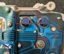
Important disconnect two high beam indicator light traces on the top. Just jump the rest of the trace accordingly.

Right Connector B (16-pin)
| Pin | Rewire |
|---|---|
| 2 | Must now connect to what PIN 3 went to (now goes to ABS warning indicator light) |
| 3 | Must now connect to what PIN 4 went to (now goes to check engine light) |
| 4 | NC / OPEN |
| 5 | Must now connect to what PIN 8 went to |
| 7 | NC / OPEN |
| 8 | NC / OPEN |
| 9 | NC / OPEN |
| 12 | Must now connect to PIN 4 on connector C (10pin) going to FU fuel gauge terminal |
| 14 | Must now connect to what PIN 7 went to |
| 15 | Must now connect to what PIN 9 went to |
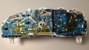
A picture of all the mods that have been applied.

ODO Correction
If you want to correct yours to avoid getting in trouble by road inspection service. You will have to change it back to your old ODO meter milage.
Please do not abuse this trick.. I have set mine from around 110.000 to 300.000. Just so I don't get in trouble.
In the image below you can see how I did it.


Notes on the Modification
Leave the four lamps open (remove bulb). Do this for: open door warning, SRS airbag warning, park warning lights in the bottom left corner under connector A. Also next to connector A you have a the indicator light and a triangle warning light. Leave the triangle warning light open too. All these light are unused and not connected, connecting them might short something not reverse engineered. They must all be left OPEN FLOATING (important).
Night time backlight

