Difference between revisions of "Dali D8X3N Thermal Camera"
Gamerpaddy (talk | contribs) m (→Flash Contents: added actual cleared pixelmap bin) |
Gamerpaddy (talk | contribs) m (breakout board setback) |
||
| (15 intermediate revisions by the same user not shown) | |||
| Line 1: | Line 1: | ||
| − | + | =Dali D8X3N Thermal Camera Reverse Engineering= | |
<br /> | <br /> | ||
| Line 48: | Line 48: | ||
<br /> | <br /> | ||
| − | + | ==D8X3N Module closer look== | |
From now on, i will refer to the Thermal Imaging Module as TIM | From now on, i will refer to the Thermal Imaging Module as TIM | ||
| Line 84: | Line 84: | ||
| − | + | ==Viewing the Video Stream== | |
[[File:Onvif Device Manager ODM.png|thumb|ODM streaming the Thermal view]] | [[File:Onvif Device Manager ODM.png|thumb|ODM streaming the Thermal view]] | ||
when first connecting it to power and Ethernet, the camera will have 192.168.1.102 as a Static ip. | when first connecting it to power and Ethernet, the camera will have 192.168.1.102 as a Static ip. | ||
| Line 140: | Line 140: | ||
| − | + | ==Viewing Raw Thermal Data from the Web API== | |
there is a hidden endpoint in the stream.so file that could be found while decompiling | there is a hidden endpoint in the stream.so file that could be found while decompiling | ||
| Line 150: | Line 150: | ||
we are mainly interessted in Raw thermal data. | we are mainly interessted in Raw thermal data. | ||
| − | ==== | + | ====Source (Stream Type)==== |
*<code>Major</code> - Main video stream (channel 0) | *<code>Major</code> - Main video stream (channel 0) | ||
| Line 160: | Line 160: | ||
*<code>YUV</code> - YUV raw video stream | *<code>YUV</code> - YUV raw video stream | ||
| − | ==== | + | ====Type (Data Format)==== |
*<code>H264</code> - H.264 video encoding | *<code>H264</code> - H.264 video encoding | ||
| Line 168: | Line 168: | ||
*<code>FRAME</code> - Frame-based format | *<code>FRAME</code> - Frame-based format | ||
| − | ==== | + | ====Mode (Transport Protocol)==== |
*<code>TCP</code> - TCP streaming (default) | *<code>TCP</code> - TCP streaming (default) | ||
| Line 174: | Line 174: | ||
*<code>MUL</code> - Multicast streaming | *<code>MUL</code> - Multicast streaming | ||
| − | ==== | + | ====Quality Parameters==== |
*<code>Quality=[1-100]</code> - Video quality level | *<code>Quality=[1-100]</code> - Video quality level | ||
| Line 180: | Line 180: | ||
*<code>Interval=[ms]</code> - Frame interval in milliseconds | *<code>Interval=[ms]</code> - Frame interval in milliseconds | ||
| − | ==== | + | ====Network Parameters==== |
*<code>IPAddr=[ip]</code> - Client IP address for UDP/multicast | *<code>IPAddr=[ip]</code> - Client IP address for UDP/multicast | ||
| Line 186: | Line 186: | ||
*<code>Heart-beat=[Yes/No]</code> - Enable/disable heartbeat | *<code>Heart-beat=[Yes/No]</code> - Enable/disable heartbeat | ||
| − | ==== | + | ====Snapshot Parameters==== |
| − | *[[File:Dali D8X3N Raw Thermal viewer.png|thumb|Raw Data Viewer in python]] | + | *<code>Snap=[Yes/No]</code> - Enable snapshot mode |
| + | |||
| + | |||
| + | |||
| + | <br /> | ||
| + | ====Raw Viewer for PC (Python)==== | ||
| + | [[File:Dali D8X3N Raw Thermal viewer.png|thumb|Raw Data Viewer in python]] | ||
| Line 195: | Line 201: | ||
it is low fps tho, due to bad optimizations. | it is low fps tho, due to bad optimizations. | ||
| − | https://pastebin.com/dyNWDPT3 | + | rev1 first working version https://pastebin.com/dyNWDPT3 |
| + | |||
| + | rev2 with temperature readout https://pastebin.com/u107Q85w | ||
| + | |||
| + | rev3 and onward will only be available directly as a Webpage on the Device (see below). | ||
| + | |||
| + | ====Raw Viewer for the internal Webserver (recommended)==== | ||
| + | It is also possible to use the Raw viewer directly in the browser. | ||
| + | |||
| + | To achieve this, the stream had to be proxied from port 5000 to 80 due to CORS. | ||
| + | |||
| + | luckily the internal lighttpd had the CGI module enabled, so piping it troug (using wget ... i know) worked with very low overhead. | ||
| + | |||
| + | |||
| + | To install, you need '''Terminal access''' to the Camera. see below. | ||
| + | |||
| + | optional for simplicity: '''ftp''' access | ||
| + | |||
| + | |||
| + | [[File:Dali D8X3N Webviewer.png|thumb|Web Raw Viewer with histogram (rev3)]] | ||
| + | |||
| + | Create the files and the code inside. | ||
| + | |||
| + | '''/app/web/webpages/raw.html''' https://pastebin.com/kaiXwAgD | ||
| + | |||
| + | and | ||
| + | |||
| + | '''/app/web/webpages/cgi-bin/proxy.cgi''' https://pastebin.com/vii1HXcU | ||
| + | |||
| + | |||
| + | then run | ||
| + | chmod +x /app/web/webpages/cgi-bin/proxy.cgi | ||
| + | '''restart''' your camera. | ||
| + | It should be accessible now trough '''http://<camera ip>/raw.html''' in the browser and click Start Stream | ||
| + | '''NOTE''': ''<u>If it does not work</u>'', check the contents of both files. FTP sometimes messes them up. | ||
| + | also run | ||
| + | dos2unix /app/web/webpages/cgi-bin/proxy.cgi | ||
| + | because linux <> windows difficulties that couldnt be resolved in over 30 years. | ||
| + | <blockquote> | ||
| − | + | performance may need improvement.</blockquote> | |
| − | |||
| − | + | ||
| − | + | ||
| + | ==Getting Root Terminal Access== | ||
| + | To access the Terminal you need to solder or plug in a UART connection to Connector J7 on the "Glue" board. | ||
| − | 3.3V | + | Pinout is (left to right) '''RX TX GND 3.3V Baud 115200 3.3V!''' |
| − | But the system will spam with debug messages, making patching the files a hard job unless you use "tftp" or "sed". | + | But the system will spam with debug messages, making patching the files a hard job unless you use "tftp" or "sed" commands. |
<br /> | <br /> | ||
| − | === | + | ====Enabling Telnet access to make patching easier==== |
[[File:Upgrade ici dali firmware updater.png|thumb|ICI Firmware updater software with modified firmware loaded]] | [[File:Upgrade ici dali firmware updater.png|thumb|ICI Firmware updater software with modified firmware loaded]] | ||
| Line 222: | Line 267: | ||
there is a easier way using a modified Firmware updater to enable Telnet temporarily to patch the Files. | there is a easier way using a modified Firmware updater to enable Telnet temporarily to patch the Files. | ||
| − | Download the upgrade_ici.exe form [https://archive.org/details/fwupdate here] and run it. | + | Download the '''upgrade_ici.exe''' form [https://archive.org/details/fwupdate here] and run it. |
| + | |||
| + | Then you should be able to connect to it via Telnet. | ||
| + | |||
| + | The Login credentials are '''User: roo'''t '''Password: DLroot''' | ||
| + | |||
| + | |||
| − | + | <br /> | |
| + | |||
| + | ===Patching Device=== | ||
===Patching the Web Server=== | ===Patching the Web Server=== | ||
| + | <br /> | ||
| + | |||
| + | ====Enabling Telnet and ftpd permanently==== | ||
| + | |||
| + | |||
This only works if you also patch the Thermal Camera module flash! | This only works if you also patch the Thermal Camera module flash! | ||
| − | + | to permanently enable Telnet, go to '''/etc/init.d''' and edit '''S90app''' | |
vi S90app | vi S90app | ||
| − | in vi, move your cursor to the # at #telnetd and press x | + | in vi, move your cursor to the '''#''' at '''#telnetd''' and press x<blockquote>optional: enable ftp by removing the '''#''' at '''ftpd''' and adjust the path to / </blockquote>now press ''':''' and type '''wq''' and hit '''enter'''. this should be it. |
| + | |||
| + | |||
| − | |||
| − | |||
| − | ==== | + | ====Patching the decoder and streamer to 640x480:==== |
go to /app and edit the mach.cfg | go to /app and edit the mach.cfg | ||
| Line 246: | Line 304: | ||
repeat that procedure for the dali.cfg | repeat that procedure for the dali.cfg | ||
| + | =====(optional) patching app.sh to prevent it from rebooting===== | ||
| + | edit the app.sh in /app and remove all "reboot" occasions to prevent the camera from rebooting if onvifserver, httpd or daliServer arent running for debugging purposes. | ||
| − | |||
| − | |||
| − | ===Patching the Thermal Camera module=== | + | <br /> |
| + | |||
| + | ====Patching the Thermal Camera module==== | ||
To patch it, you need to disassemble everything down to the FPGA Board, | To patch it, you need to disassemble everything down to the FPGA Board, | ||
| − | on the bottom there is a SPI SOIC8 Flash. | + | on the bottom there is a SPI SOIC8 Flash. |
Use a CH341 EEPROM programmer (be sure to have a fixed or modified version to not put out 5V!, set it to 3.3V) and SOIC8 clamp. | Use a CH341 EEPROM programmer (be sure to have a fixed or modified version to not put out 5V!, set it to 3.3V) and SOIC8 clamp. | ||
| Line 262: | Line 322: | ||
Dont forget to download a backup of your flash and save it ! | Dont forget to download a backup of your flash and save it ! | ||
| − | Download the Binary 640x480 cleared pixelmap from below and load it into NeoProgrammer, | + | |
| + | Download the Binary "Dali 640x480 '''actual''' cleared pixelmap.bin" from #3 below and load it into NeoProgrammer, | ||
| + | |||
| + | Click Erase, Program and Verify. | ||
This can take a while. | This can take a while. | ||
Your imager should start up right after assembly by hearing the shutter click. | Your imager should start up right after assembly by hearing the shutter click. | ||
| − | + | ||
| + | |||
| + | ==Hardware Hacking== | ||
| + | |||
===Flash Contents=== | ===Flash Contents=== | ||
| − | + | On archive, click on show all files to download them. | |
| + | |||
| − | a Flash dump of a original 640x480 model can be found [https://archive.org/details/d-843-n-640x-480 here] | + | <nowiki>#</nowiki>1 a Flash dump of the original downgraded D8X3N can be found [https://archive.org/details/dali-d-843n-flash-dump here] |
| + | |||
| + | <nowiki>#</nowiki>2 a Flash dump of a original 640x480 model can be found [https://archive.org/details/d-843-n-640x-480 here] | ||
| + | |||
| + | <nowiki>#</nowiki>3 a modified Flash dump of a 640x480 with cleared dead pixel map, flat map etc. can be found [https://archive.org/details/d-843-n-640x-480-cleared-pixelmap here] | ||
| − | |||
a Flash dump of the web server SPI flash W25Q256JV can be found [https://archive.org/details/dm-60-webserver-flash-dump here] in case a bad firmware update caused a bootloop. | a Flash dump of the web server SPI flash W25Q256JV can be found [https://archive.org/details/dm-60-webserver-flash-dump here] in case a bad firmware update caused a bootloop. | ||
| Line 310: | Line 380: | ||
</syntaxhighlight><br /> | </syntaxhighlight><br /> | ||
| − | + | ====Settings offset 0x200000==== | |
The settings are read and written every startup, aswell when you close the OSD, sporadically and when executing the command MSV | The settings are read and written every startup, aswell when you close the OSD, sporadically and when executing the command MSV | ||
| Line 347: | Line 417: | ||
<br /> | <br /> | ||
| − | + | ====Bad Pixel and Flatframe Maps 0x280000 and 0x4C0000==== | |
Thermal cameras require a bad pixel and flat frame map to compensate for manufacturing inconsistencies. | Thermal cameras require a bad pixel and flat frame map to compensate for manufacturing inconsistencies. | ||
| Line 375: | Line 445: | ||
| − | + | ==Dali Commands== | |
To control the TIM you can either use Pelco or Dali command set. By default the Dali commandset is used at 38400 BAUD. | To control the TIM you can either use Pelco or Dali command set. By default the Dali commandset is used at 38400 BAUD. | ||
| Line 601: | Line 671: | ||
| + | |||
| + | |||
| + | ==Secret Menu Overview== | ||
| + | The secret menus Main and System can be openend with the password '''+-MC+-''' | ||
| + | |||
| + | |||
| + | Its structured like this, not all variables have been figured out yet. | ||
| + | |||
| + | The format is Menu: submenu: submenu: | ||
| + | |||
| + | and for menu entries: Name, default value, command, description or messages that pop up. | ||
| + | <br /><syntaxhighlight lang="vb"> | ||
| + | MAIN & SYSTEM PASS: +-MC+- | ||
| + | |||
| + | entries are NAME VALUE COMMAND DESC or if its a folder its just ":" | ||
| + | |||
| + | System: | ||
| + | System: | ||
| + | Gain 255 SCO | ||
| + | Bright 102 IBR | ||
| + | BenDi 100 ? | ||
| + | BenDiContrase 80 ? | ||
| + | DisMode 0 ? | ||
| + | Frequency 48hz (24,25,48,50) | ||
| + | DigitalOut 8-14bit 14bit, BT656(_P), ?, BT601 | ||
| + | AutoFocus N ? | ||
| + | Line 1 ? | ||
| + | Ltemp0 11800 ? | ||
| + | LTemp1 11000 ? | ||
| + | HTemp0 9500 ? | ||
| + | HTemp1 8700 ? | ||
| + | DelayTime 0 ? | ||
| + | Enhance 0-1 ? | ||
| + | Enhanced E1 230 ? | ||
| + | FPA_Gain 12pF ? between 4 and 18 at random. | ||
| + | NUCEn N ? | ||
| + | |||
| + | |||
| + | Area: | ||
| + | SE 2 ASN 0-4 "Partition" | ||
| + | INT 200 INT "Points time" | ||
| + | VS 3161 SVS | ||
| + | VF 2800 SVF | ||
| + | Vtemp 1401 VTP | ||
| + | VtempArea Low ? | ||
| + | VtempBase 13500 ? | ||
| + | VtempStep -1 ? | ||
| + | VsStep 8 ? | ||
| + | DeadPixelModel preset / calculate | ||
| + | DP: Cursor to select dead pixels | ||
| + | X 360 position | ||
| + | Y 288 position | ||
| + | AutoBP: 50 Press C to start automatic dotting | ||
| + | Quit? Number of bad pixels 961& "Blind element replacement in progress" | ||
| + | Undo | ||
| + | R2: Save data? blind pixel replacement in progress | ||
| + | Replace Y N = DPI, Y = API | ||
| + | L: Reading parameters | ||
| + | S: Saving parameters | ||
| + | |||
| + | Debug: | ||
| + | Rectify N | ||
| + | DisplayGary N | ||
| + | TE N SDT | ||
| + | AutoE ? ? | ||
| + | AutoVS Y ? | ||
| + | VSGrayH 8000 ? | ||
| + | VSGrayL 7000 ? | ||
| + | Trends 1 ? | ||
| + | Shelter N ? | ||
| + | MotorCon 3 ? | ||
| + | SaveFactoryPara: | ||
| + | LanTyp EN ? LANGUAGE | ||
| + | DisplayMT N ? | ||
| + | Version: | ||
| + | PRJ D843 DLD640 ImLib, MTlib, Soft, Logic | ||
| + | |||
| + | BackDispose: | ||
| + | GammaEN 1 ? | ||
| + | Gain 1 ? | ||
| + | EnhanceEN 0 ? | ||
| + | Hpf_shift 5 ? | ||
| + | Hpf_thrd 5 ? | ||
| + | Enhance 150 ? | ||
| + | Lthrd 50 ? | ||
| + | |||
| + | Monitor: | ||
| + | Opens normal OSD | ||
| + | |||
| + | Alarm Set: | ||
| + | Alarm Switch Y ? | ||
| + | Alarm Mode No ? | ||
| + | Alarm Temperature -1°C ? | ||
| + | Reference Gray Y ? | ||
| + | Alarm Level 1L ? | ||
| + | Alarm Gray 65535 ? | ||
| + | Alarm PointNum 0 ? | ||
| + | Correct Gray 0 ? | ||
| + | |||
| + | Thermometry: | ||
| + | Data Collection 0 SMS | ||
| + | Interval 60 SCP | ||
| + | Ammount 90 SCT | ||
| + | Environment normal ? | ||
| + | Export: | ||
| + | Displays: Exportin normal temperature MTC data | ||
| + | Correction -1 ? | ||
| + | Emissivity 100 SEM | ||
| + | Calibration: | ||
| + | BlackbodyTemp -10 grabs a val from GAB | ||
| + | Save CBS | ||
| + | Cancel CBD | ||
| + | Correction: | ||
| + | BlackbodyTemp -10 Picks from the list GAR | ||
| + | Grayscale 0 SLG | ||
| + | Confirm LRE | ||
| + | Save LRS | ||
| + | Cancel LRD | ||
| + | Ninepoint measurement SMV | ||
| + | |||
| + | Cursor: | ||
| + | Cur N DRC enable cursor | ||
| + | X 320 SRP set cursor position | ||
| + | Y 240 SRP set cursor position | ||
| + | |||
| + | Main: | ||
| + | Auto 2 SAG Auto gain | ||
| + | G 211 SVC | ||
| + | B 10002 SVB | ||
| + | P 1 SWP polarity | ||
| + | Z X ? | ||
| + | Settings: | ||
| + | Image: | ||
| + | FI Y ? | ||
| + | FIValue 0 ? 0-31 | ||
| + | Freeze N Freeze image | ||
| + | VE N SMR Vertical flip | ||
| + | HO N SMR Horizontal flip | ||
| + | AutoCali L same as rectify? | ||
| + | O IN internal or external | ||
| + | COM: | ||
| + | Opens UART menu | ||
| + | AvoidburnSwitch OFF enable anti burn in | ||
| + | ProtectedTime 10S duration | ||
| + | AvoidBurn 16383 threshold to trigger antiburn | ||
| + | |||
| + | </syntaxhighlight> | ||
| + | |||
| + | ===Automatic Dead Pixels and Flatmap Correction=== | ||
| + | |||
| + | |||
| + | It it possible to generate a new flat and dead pixel map automatically within the camera after flashing the cleared-map binary. | ||
| + | <br /> | ||
| + | |||
| + | =====Dead pixels:===== | ||
| + | In the secret menu "System", navigate to Area - DeadPixelModel and set the AutoBP (sensitivity for auto bad pixel finding) to 50 or so. Then press C Button | ||
| + | |||
| + | This can take a while. | ||
| + | [[File:High emissivity peltier black body.jpg|thumb|A Peltier / TEC coated in Candle sood to give it a high emissivity surface. It can be cooled or heated by swapping the polarity. ]] | ||
| + | |||
| + | |||
| + | Afterwards, navigate to S: and press + to save it. | ||
| + | <br /> | ||
| + | |||
| + | =====Flatfield:===== | ||
| + | In the Debug menu navigate to R2 and press + | ||
| + | |||
| + | now place something '''Cold''' infront of the Camera with a high emissivity. (it needs to fill the whole image) | ||
| + | |||
| + | Press '''+''', wait for it to says High temperature. | ||
| + | |||
| + | Place something '''Hot''' infront and press '''+''' again. | ||
| + | |||
| + | Afterwards, save with '''S:''' again. | ||
| + | |||
| + | Flatfield should now be calibrated | ||
| + | <br /><blockquote>Note: Not all dead pixels are auto detected or get removed. you can manually select them in the Dead pixel editor but its not known yet how to select and correct them.</blockquote> | ||
| Line 606: | Line 853: | ||
<br /> | <br /> | ||
| − | + | ==Using the Thermal module without Webserver== | |
[[File:Dali D8X3C Breakout board.png|thumb|Breakout board for D8X3C ]] | [[File:Dali D8X3C Breakout board.png|thumb|Breakout board for D8X3C ]] | ||
to use it, you need to interface it directly. | to use it, you need to interface it directly. | ||
| Line 620: | Line 867: | ||
| − | + | A breakout board is still a work in progress | |
| Line 630: | Line 877: | ||
<br /> | <br /> | ||
| − | + | ==Sensor Pinout== | |
[[File:Dali DLD384 Sensor pinout basic.png|thumb|basic pinout of a DLD384]] | [[File:Dali DLD384 Sensor pinout basic.png|thumb|basic pinout of a DLD384]] | ||
the pinout of the thermal sensor havent been analyzes much. | the pinout of the thermal sensor havent been analyzes much. | ||
Latest revision as of 00:26, 6 August 2025
Contents
- 1 Dali D8X3N Thermal Camera Reverse Engineering
- 1.1 Introduction
- 1.2 D8X3N Module closer look
- 1.3 Viewing the Video Stream
- 1.4 Viewing Raw Thermal Data from the Web API
- 1.5 Getting Root Terminal Access
- 1.6 Hardware Hacking
- 1.7 Dali Commands
- 1.8 Secret Menu Overview
- 1.9 Using the Thermal module without Webserver
- 1.10 Sensor Pinout
Dali D8X3N Thermal Camera Reverse Engineering
Introduction
The Dali D8X3N Thermal Camera module comes in two versions, a 384x288 and 640x480 resolution, utilizing the DLD Series of amorphous-Silicon Microbolometers.
They were mainly used in Dali DM60-W or WS-1 Body Temperature screening cameras in conjunction with a Black Body radiator set to 37°C to detect infected individuals at the start of the 2020 Covid Pandemic.

ICI rebranded these models as FM 320 P and FM 640 P, and distributed them on the local US market, but as the need for such Cameras exploded, those models were built with what was in stock.
So happens, that some of the FM 320 P Models had a DLD640 640x480 instead of a DLD384 384x288 Microbolometer in them, and just got their Firmware modified.
It also could be, because they have excessive amounts of bad pixels outside the 384x288 area, that they were binned to a lower grade.
Discussions about these Cameras started around 2022 in the EEVBlog Forums. when they started to appear secondhand and affordable.
Originally they were priced around US$ 20... 30.000 by ICI, and a unknown amount by Dali Tech.
The Modules specs according to the manufacturer are:
≤50..60mK@F1,300K,50Hz
17 or 25µm pixel pitch
Hisilicon SoC running Linux to provide Onvif and RTSP streams, analysis and a Web UI

ICI FM Cameras are found all over Online secondhand marketplaces for scrap Prices, as they are no longer needed.
But you never know, what are you getting. It could be a real DLD384 or the better DLD640 inside. Its a gamble.
640x480 Imagers
are labeled 22D843 Nxxxx and have a DLD640 sensor in it, they can be upgraded if they run the 384x288 firmware.
384x288 Imagers
are labeled 22D883Nxxxx and have a DLD384 sensor in it, they cannot be upgraded
D8X3N Module closer look
From now on, i will refer to the Thermal Imaging Module as TIM
On the front there is a 2 Element Germanium Lens of a unknown focal length and aperture.
It can be focus-adjusted when unscrewing the clamp around the housing. It can be focussed from infinity down to 10..20cm with some quality loss.
The outter diameter of the Lens is 42mm with a 1 1/3 inch thread diameter of undetermined pitch.
Dimensions of the germanium elements are 21mm to 3 and 6mm and 14grams in weight.

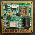
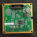
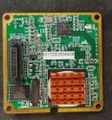
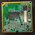
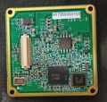
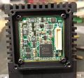
The TIM is composed of 6 Stacked PCB modules, 3 of which are for the Web Server functionality. taking them off will give you the basic configuration of a Dali D8X3C TIM
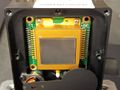
DLD640 Sensor
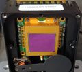
DLD384 Sensor
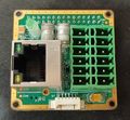
Network & GPIO Board Back
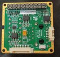
Network & GPIO Board Front
Board between Logic and IO Back
Board between Logic and IO Front
SoC Board back
SoC board front
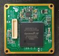
FPGA Board of the D8X3C Thermal Imager including a PMIC
FPGA Board Front with Video DAC and SPI Flash
Sensor control and ADC board
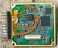
Debug wiring for sniffing SPI and UART


User Manual
including pinout diagram and important data
can be found here https://archive.org/details/dali-d-8-x-3-cuser-manualen-v-1.0-1
Viewing the Video Stream

when first connecting it to power and Ethernet, the camera will have 192.168.1.102 as a Static ip.
If you are running a 192.168.0.x or .178.x net, you need to change it or add a subnet under windows ipv4 settings.
to view it, you can use VLC and the stream URL
rtsp://admin@admin:<camera ip>/ONVIFMedia
there is /ONVIFMedia /ONVIFMediaM and /ONVIFMediaS for different stream Profiles.
VLC is quite slow and delayed, rather use Onvif Device Manager ODM,
it has no delay and auto-detects cameras in the network.
Be sure to log in as user: admin pass: admin in ODM.
in there, you can also set you camera to DHCP under Network settings.
Web Interface

the web interface can be accessed by opening the camera IP in a browser
login is:
user: admin pass: admin
You can set Temperature markers and areas, but without using the Black Body calibration source, your readings may be way off or not working.
OSD
there is a debug-login with
user: super pass: 871897
that lets you send Key commands to the Imager to navigate the OSD.
Setting the OSD to english is accomplished with option #11

To acces some locked menus, press
+ - + - + -
The password for the locked System and Main menu is
+-MC+-
Be careful in the UART menu to not change the BAUD rate or Protocol, as your ability to control it via the Web API gets lost.
You need to reflash or solder buttons on the thermal core then.
Viewing Raw Thermal Data from the Web API
there is a hidden endpoint in the stream.so file that could be found while decompiling
accessing

<ip of camera>:5000/stream?Type=JPEG&Source=Jpeg&Mode=TCP
lets you download a JPEG. but there are more options available (not all have been tested)
we are mainly interessted in Raw thermal data.
Source (Stream Type)
Major- Main video stream (channel 0)Minor- Sub video stream (channel 1)MinorAV- Sub video + audio streamMajorAV- Main video + audio streamJpeg- JPEG snapshot streamRaw- Raw thermal data streamYUV- YUV raw video stream
Type (Data Format)
H264- H.264 video encodingJPEG- JPEG image formatRAW- Raw sensor dataQBOX- Custom protocol formatFRAME- Frame-based format
Mode (Transport Protocol)
TCP- TCP streaming (default)UDP- UDP streamingMUL- Multicast streaming
Quality Parameters
Quality=[1-100]- Video quality levelFrames=[number]- Number of frames to sendInterval=[ms]- Frame interval in milliseconds
Network Parameters
IPAddr=[ip]- Client IP address for UDP/multicastPort=[port]- Client port for UDP/multicastHeart-beat=[Yes/No]- Enable/disable heartbeat
Snapshot Parameters
Snap=[Yes/No]- Enable snapshot mode
Raw Viewer for PC (Python)

To view the raw stream, i made a python program that converts the 14bit thermal data to a visible image.
it is low fps tho, due to bad optimizations.
rev1 first working version https://pastebin.com/dyNWDPT3
rev2 with temperature readout https://pastebin.com/u107Q85w
rev3 and onward will only be available directly as a Webpage on the Device (see below).
Raw Viewer for the internal Webserver (recommended)
It is also possible to use the Raw viewer directly in the browser.
To achieve this, the stream had to be proxied from port 5000 to 80 due to CORS.
luckily the internal lighttpd had the CGI module enabled, so piping it troug (using wget ... i know) worked with very low overhead.
To install, you need Terminal access to the Camera. see below.
optional for simplicity: ftp access

Create the files and the code inside.
/app/web/webpages/raw.html https://pastebin.com/kaiXwAgD
and
/app/web/webpages/cgi-bin/proxy.cgi https://pastebin.com/vii1HXcU
then run
chmod +x /app/web/webpages/cgi-bin/proxy.cgi
restart your camera.
It should be accessible now trough http://<camera ip>/raw.html in the browser and click Start Stream
NOTE: If it does not work, check the contents of both files. FTP sometimes messes them up.
also run
dos2unix /app/web/webpages/cgi-bin/proxy.cgi
because linux <> windows difficulties that couldnt be resolved in over 30 years.
performance may need improvement.
Getting Root Terminal Access
To access the Terminal you need to solder or plug in a UART connection to Connector J7 on the "Glue" board.
Pinout is (left to right) RX TX GND 3.3V Baud 115200 3.3V!
But the system will spam with debug messages, making patching the files a hard job unless you use "tftp" or "sed" commands.
Enabling Telnet access to make patching easier

there is a easier way using a modified Firmware updater to enable Telnet temporarily to patch the Files.
Download the upgrade_ici.exe form here and run it.
Then you should be able to connect to it via Telnet.
The Login credentials are User: root Password: DLroot
Patching Device
Patching the Web Server
Enabling Telnet and ftpd permanently
This only works if you also patch the Thermal Camera module flash!
to permanently enable Telnet, go to /etc/init.d and edit S90app
vi S90app
in vi, move your cursor to the # at #telnetd and press x
optional: enable ftp by removing the # at ftpd and adjust the path to /
now press : and type wq and hit enter. this should be it.
Patching the decoder and streamer to 640x480:
go to /app and edit the mach.cfg
replace DL384 with D640 and edit the resolution to 640 480
(press i in vi to enter edit mode, press ESC to exit edit mode. :wq to write and quit.)
repeat that procedure for the dali.cfg
(optional) patching app.sh to prevent it from rebooting
edit the app.sh in /app and remove all "reboot" occasions to prevent the camera from rebooting if onvifserver, httpd or daliServer arent running for debugging purposes.
Patching the Thermal Camera module
To patch it, you need to disassemble everything down to the FPGA Board,
on the bottom there is a SPI SOIC8 Flash.
Use a CH341 EEPROM programmer (be sure to have a fixed or modified version to not put out 5V!, set it to 3.3V) and SOIC8 clamp.
Use NeoProgrammer (i used 2.2.0.10 but there are newer available, use the latest) and click Detect. It should find W25Q128 chips, select the FV one.
Dont forget to download a backup of your flash and save it !
Download the Binary "Dali 640x480 actual cleared pixelmap.bin" from #3 below and load it into NeoProgrammer,
Click Erase, Program and Verify.
This can take a while.
Your imager should start up right after assembly by hearing the shutter click.
Hardware Hacking
Flash Contents
On archive, click on show all files to download them.
#1 a Flash dump of the original downgraded D8X3N can be found here
#2 a Flash dump of a original 640x480 model can be found here
#3 a modified Flash dump of a 640x480 with cleared dead pixel map, flat map etc. can be found here
a Flash dump of the web server SPI flash W25Q256JV can be found here in case a bad firmware update caused a bootloop.
Flash Binary Analysis
The Flash IC is a Winbond 25Q128JV SPI Flash that contains the FPGA Bitstream, Deadpixel and Flatmap, aswell as the Device Settings.
a copy of the SPI Logic Capture at startup can be found here, the free software DSView from DreamSourceLab is required to view it.

a approximation of the offsets resulted in this list:
0x000000	-	altera cyclone iv stuff
0x200000	-	settings
0x280000	-	Flat field correction map
0x4C0000	-	Bad Pixel correctio nmap
0x580000	-	image aswell? 36010 bytes
0x740000	-	GUIX?
0x7C0000	-	Strings for Gui?
0x800000	-	another shorter GUIX
0x880000	-	Strings for second gui?
0x8C0000	-	GUIX
0x940000	-	Strings for gui
0xE00000	-	?
0xE80000	-	dzxg? short
0xEC0000	- 	crosshair.bmp
0xF40000	-	3DTM?
0xF80000	-	fake? Bad pixel map BPRP
Settings offset 0x200000
The settings are read and written every startup, aswell when you close the OSD, sporadically and when executing the command MSV
these are some of the settings i could figure out by changing and watching the logic capture what changed.
offset size Cmd
0x0		1	SAG  	(0-2) auto gain
0x2		2	SVB	 	(0-16383) saved value is 16383 - SVB
0x4		2	SVC		(0-1023) set exposure or gain
0x6		1	SSM		image filtering
0x8		1	SEH		image enhancement
0xA		1	SWP		invert b/w polarity
0x14	1	SMR		Flip
0x16	1	SMR		Mirror
0x20	1	MENU	Cal source 0 IN, 1 OUT
0x3A	1	MENU	Enhance value 0-100
0x40	1	MENU	Rectify (shutter 0 OFF, 1 L, 2 H)
0x50	1	MENU	Language 0 english, 1 chinese, 2 russian
0xA2	-	SCO		set contrast gain
0xA4	-	IBR 	set brightness
0xAE	2	MENU	Fire Threshold
0xAC	1	SPA		set color palette
0xE2	1	SMS		display "collected 0/80" enabled
0xF8	1	SEM		set emissivity
0x110	1	SRT		set revise temp
0x116	1	SHD		set humidity
0x118	1	SET 	set ambient temp
0x11A	1	STD		set temp range
0x120	2	SLG		-500 to 500?
0x124	2	SRD		set distance
0x12C	1	SCP		???
0x130	2	SCT		???
So i let the AI create a Configurator page that lets you change the Settings in your Flashdump to your liking
Bad Pixel and Flatframe Maps 0x280000 and 0x4C0000
Thermal cameras require a bad pixel and flat frame map to compensate for manufacturing inconsistencies.
unfourtainly, the maps of the downgraded cameras only contain enough data for a 384 model, not the full 640.
at offset 0xF80000 there is a BPRP which was mistaken at first as the Bad pixel map, it could just be a mask to where to apply the offset maps, as its either 0x0 or 0x1.
The Viewer Page is written in JS and does not require any special dependencies, it can run as a plain html file offline.
There still needs to be work done to create own maps and flatfields but the cameras are still very capable and useable with fully cleared maps.
To clear the maps, just go to these offsets and fill with values around 0x3F or 0x0 for total length of X Resolution x Y Resolution x 2 bytes (0x96000 for 640x480)

Dali Commands
To control the TIM you can either use Pelco or Dali command set. By default the Dali commandset is used at 38400 BAUD.
Those commands consist of a 0x02 start byte followed by two length Bytes, then the actual command which is allways 3 uppercase Letters in ASCII (eg. KBD for keyboard) followed by a comma and the values.
Some commands take multiple values, some dont. But you allways have to send the comma after the Command.
The camera will answer with the Command and 0, 1 or 2. Sending no value counts as zero.
0 is invalid parameters, too few or out of range
1 is OK, valid command
2 is Invalid command
Commands can be sent trough the Web server using the URL Api endpoint or directly trough the UART port.
(keyboard, C button, causes the shutter to do a calibration)
<camera ip>/cgi-bin/dmcmd?Command=KBD,C
Listening to the answer can be done while being in the Linux shell and typing
cat /dev/ttyAMA2 | strings
By bruteforcing the UART with AAA to ZZZ a list of Commands could be obtained, but some with unknown Parameters or functionality yet. including some from a decompiled DM60comm.so module found in /app/modules folder.
KBD		KEY			Keyboard (F S M C + -)
SSM		0-1			Image Filtering Off/On
GSM		0			Image filter status
SEH		0-1			Image Enhancement Off/On
GEH		0-1			Image enhancer status
SCO		0-255		Set Gain (locked when SAG auto gain is on)
GCO		0-255		Get gain
INT		15-320		set actual gain? not just contrast sometimes disabled?
IBR		0-255		Set brightness
GBR		0-255		Get brightness
SMR		0-3			Mirror mode bit0=horizontal, bit1=vertical
GMR		0			Get rotation/flip
SDT		0-1			displays temp=44.65°C osd, but webserver sends date/time to the cam there....
GDT		0-1			Get temp display active?
GPT					Display temp oft SDT
GNU		0-1			Get Shutter closed/open
SNU		0-1 		Shutter close / open
STD		0-1			Set Range 0: -20-180°C 1: 100-600°C
GTD		0-1			Get Range
SET		°C			Set Ambient temperature
GET		°C			Get Ambient temperature
SEM		0-100		0-1 set emissivity x100
GEM		0-100		Get Emissivity
SRT		°C			Set revise temperature -100-100 -10-10°
GRT		°C			Get revise temperature
SRD		100			Set Distance 4.4m x100
GRD		100			Get Distance
SHD		0-100		Set Humidity
GHD		55			Get Humidity
SWP		0-1			invert s/w polarity image
GWP		1			is inverted?
SPA		0-10?		Set color palette
GPA		3			white hot
SMV		0-1			Show temperature 3x3 grid?? in combination with GTV maybe
GMV		0
SMS		0-1			displays "collected 0/<number set by SCT>" by SCP delay "saves the daily number of highest temperatures?"
GMS		0
SCT		1-500		sets the amount of "collected" points for SMS
GCT		80
SCP		5-60		"collected" delay in seconds for SMS
GCP		60
SAG		0-2			Auto brightness / gain
GAG		0
SLR		0-9			???
GLR		0
SRP		0,0 - 639,479		set crosshair position
GRP		320,240		get crosshair position
DRC		0-1			Show crosshair
SLG		-500-500	??
GLG
SCE 	text		??
GCE		0
SCB 	text		??
GCB		0
SVB		0-16383		adc offset, exposure? good at 9650
GVB		6733		value is 16383 minus SVB
SVC		1-1023		set contrast but better
GVC		260
SVF		100-?		?? video freaks out 3400 seems good
SVS		100-?		?? video freaks out 3300 seems good
SOT		0-1			?? sensor supply, looks weird when off.
SZM		1-4			?
GZM		1
MSV					save settings too eeprom
ASV					Saves something aswell?
GCS		0			Get Core status & faults
ALD		0,2?		video blanks lots of eeprom activity. reload pixel map??
SAV		0-9999		set Fire threshold
GAV		2100		get Fire Threshold
BAC					change uart protocol? careful
CBD					Displays Recovery successful?
CBS					Displays Saved successfully
LRD					Displays Recovery successful?
LRS					Displays Saved successfully?
LRE					Displays Temperature Repair successful?
CBT					Displays Calibration successful?
DBP					??? shutter clicks
DPI					Show weird pixels
API					Hide weird pixels
CCM					??
ASN		0-4			??
GAB		4 vals		?? 3,-10,50,150
GAN		1			??
GAR		11 vals		??  10,10,5,20,35,50,70,90,120,150,180,,
GCM		6 values	??
GFV					prints screen gray value?
GIT		200			??
GTV					Get the collected temp values?
PTS					echoes but with extra stuff??
QYA		7170		Query Gray Info (information mode)
QYI		7124		Query Gray Average mode
QYM		7512		Query Gray Minimum mode
VTP		400-4000	??
MTD		U/S,0,0		?? S answers with bytes, U upload bytes?
MTC		U/S?		?? S answers with U,0,0, S doesnt.


return 0 invalid params:
STS					??
STT					??
SAC					??
SAH					??
SAS					??
SAT					??
SCX					?? displays crosshair but invalid params
SCY					?? displays crosshair but invalid params
GAC					??
GAH					??
GAS					??
GAT					??
GME					??
GPC					??
GPI					??
GPM					??
GTA					??
GTC					??
GTI					??
GTM					??
GTS					??
GTT					??

answer only:

BPM		0-1			stream ready? answers with 0 stop, 1 go, 2 when prompted
AVS		0,1
MEH
PWI		0-1			changing palette from wh to fire


unconfirmed (from dm60comm.so):
SDT		2024,03,15,14,30,25		Set Date Time with year,month,day,hour,minute,second
STS		1		Set Temperature Show display (0=off, 1=on)
SVA		2		Set Video Auto mode (0=manual, 2=auto)
SMP		0,1,1,0,100,150,200,250,300,350,90,25		Set Measurement Point (type,index,enable,mode,startX,startY,endX,endY,anchorX,anchorY,threshold,color)
STV		Stop Temperature View measurements
SPF		5		Set Profile parameter
SVL		-10		Set Video Left pan movement (signed value)
SVU		-5		Set Video Up tilt movement (signed value)
SVD		5		Set Video Down tilt movement (signed value)
SSP		17,1,0	Set System Parameter (param_id,value,index) #46 	temperature format 0 °C, 1 °F, 2 K
SCP		Set Current Preset (save current position)
GCP		Get Current Preset
STT		300,350	Set Temperature Threshold (low,high values *10)
SDC		1		Set Display Configuration parameter
GCS		Get Current Status
GMM		Get Memory Map information
GFV		Get Frame Value (grayscale data)
GFZ		Get Freeze Status
GSI		1		Get System Information (parameter=1)
GSS		Get System Status
GSP		21,0	Get System Parameter (param_21=surround temp, value=0)
GTT		Get Temperature Threshold range
GTV		1,3,10	Get Temperature Values (enable,type,count)
GNU		Get Network Update status (response command)
FRZ		Freeze current display frame
LIV		Live mode (unfreeze display)
CAL		Calibrate system
CCP		3		Call Current Preset (preset number 0-9)
APF		100	Auto Profile setting
MEH		Measure Enhancement
BPT		Built-in Test
MTC		S,0		Measure Temperature Capture (S=start, 0=sequence)
MTG		U,0,1024,<data>	Measure Temperature Gray data transfer
MTD		U,0,1024,<data>	Measure Temperature Data transfer
UFP		S,0,2048		Update Firmware Prepare (S=start, 0=offset, 2048=size)
UFD		S,0,1024		Update Firmware Data transfer
BAB		U		Buffer operation (U=update)
TTH		S,0		Temperature Threshold operation
IPP		192.168.001.102,255.255.255.000,192.168.001.001,192.168.000.001,9989,9998	IP Parameters (IP,netmask,gateway,DNS,port1,port2)
MAC		00:60:A9:10:00:01	MAC Address setting
SNP		Set Network Parameters (response command)
QYI		Query Gray Info (information mode)
QYA		Query Gray Average mode
QYM		Query Gray Minimum mode
GAI		Get Alarm Info (response command)
YTC		<data>	Unknown command with data parameter
HTH
LRS
LRD
GAR
DRC
PTS
SCX
SCY
CBT
LRE
CBD
CBS
XXX
GSP
GTT
QYI
QYA
QYM
Secret Menu Overview
The secret menus Main and System can be openend with the password +-MC+-
Its structured like this, not all variables have been figured out yet.
The format is Menu: submenu: submenu:
and for menu entries: Name, default value, command, description or messages that pop up.
MAIN & SYSTEM PASS: +-MC+-

entries are NAME VALUE COMMAND DESC or if its a folder its just ":"

System:
	System:
        Gain    255 SCO
        Bright  102 IBR
        BenDi   100 ?
        BenDiContrase   80  ?
        DisMode 0   ?
        Frequency   48hz (24,25,48,50)
        DigitalOut  8-14bit  14bit, BT656(_P), ?, BT601
        AutoFocus   N   ?
        Line    1   ?
        Ltemp0  11800   ?
        LTemp1  11000   ?
        HTemp0 9500     ?
        HTemp1 8700 ?
        DelayTime   0   ?
        Enhance   0-1 ?
        Enhanced E1  230 ?
        FPA_Gain 12pF   ? between 4 and 18 at random.
        NUCEn   N   ?


	Area:
        SE  2  ASN 0-4 "Partition"
        INT 200 INT "Points time"
        VS  3161    SVS
        VF  2800    SVF
        Vtemp 1401  VTP
        VtempArea   Low ?
        VtempBase   13500  ?
        VtempStep   -1  ?
        VsStep  8   ?
        DeadPixelModel  preset / calculate
        DP: Cursor to select dead pixels
            X 360 position
            Y 288 position
            AutoBP: 50  Press C to start automatic dotting
            Quit?   Number of bad pixels 961& "Blind element replacement in progress"
            Undo
        R2: Save data? blind pixel replacement in progress
        Replace Y   N = DPI, Y = API
        L:  Reading parameters
        S:  Saving parameters

	Debug:
		Rectify N
        DisplayGary N
        TE  N   SDT
        AutoE  ?    ?
        AutoVS  Y   ?
        VSGrayH 8000    ?
        VSGrayL 7000    ?
        Trends  1   ?
        Shelter N   ?
        MotorCon    3   ?
        SaveFactoryPara:
        LanTyp  EN  ?   LANGUAGE
        DisplayMT   N   ?
        Version:
            PRJ D843 DLD640 ImLib, MTlib, Soft, Logic

    BackDispose:
        GammaEN 1   ?
        Gain    1   ?
        EnhanceEN   0   ?
        Hpf_shift   5   ?
        Hpf_thrd    5   ?
        Enhance 150 ?
        Lthrd   50  ?

    Monitor:
        Opens normal OSD

    Alarm Set:
        Alarm Switch    Y   ?
        Alarm Mode  No  ?
        Alarm Temperature   -1°C  ?
        Reference Gray  Y   ?
        Alarm Level 1L  ?
        Alarm Gray  65535   ?
        Alarm PointNum  0   ?
        Correct Gray    0   ?

    Thermometry:
        Data Collection 0   SMS
        Interval    60  SCP
        Ammount     90  SCT
        Environment normal  ?
        Export:
            Displays: Exportin normal temperature MTC data
        Correction  -1  ?
        Emissivity  100 SEM
        Calibration:
            BlackbodyTemp -10   grabs a val from GAB
            Save    CBS
            Cancel  CBD
        Correction:
            BlackbodyTemp   -10 Picks from the list GAR
            Grayscale   0   SLG
            Confirm LRE
            Save    LRS
            Cancel  LRD
        Ninepoint measurement   SMV

    Cursor:
        Cur N   DRC enable cursor
        X   320 SRP set cursor position
        Y   240 SRP set cursor position

Main:
    Auto    2   SAG Auto gain
    G   211 SVC
    B   10002   SVB
    P   1   SWP polarity
    Z   X   ?
    Settings:
        Image:
            FI  Y  ?
            FIValue 0 ? 0-31
            Freeze  N   Freeze image
            VE  N   SMR Vertical flip
            HO  N   SMR Horizontal flip
            AutoCali    L   same as rectify?
            O   IN  internal or external
        COM:
            Opens UART menu
        AvoidburnSwitch OFF enable anti burn in
        ProtectedTime   10S duration
        AvoidBurn   16383   threshold to trigger antiburn
Automatic Dead Pixels and Flatmap Correction
It it possible to generate a new flat and dead pixel map automatically within the camera after flashing the cleared-map binary.
Dead pixels:
In the secret menu "System", navigate to Area - DeadPixelModel and set the AutoBP (sensitivity for auto bad pixel finding) to 50 or so. Then press C Button
This can take a while.

Afterwards, navigate to S: and press + to save it.
Flatfield:
In the Debug menu navigate to R2 and press +
now place something Cold infront of the Camera with a high emissivity. (it needs to fill the whole image)
Press +, wait for it to says High temperature.
Place something Hot infront and press + again.
Afterwards, save with S: again.
Flatfield should now be calibrated
Note: Not all dead pixels are auto detected or get removed. you can manually select them in the Dead pixel editor but its not known yet how to select and correct them.
Using the Thermal module without Webserver

to use it, you need to interface it directly.
The module will put out a Analog video signal (High-Z, need to buffer when connecting it to 75Ohm Video input)
Also a 8 or 14bit or 8-bit BT656 output.
the header exposes the FPGA JTAG and UART aswell as 6 Hardware Keys to Navigate the OSD.
To interface, you need to make a adapter board with a DF12-50DS-0.5V(86) Docking socket.
A breakout board is still a work in progress
Sensor Pinout

the pinout of the thermal sensor havent been analyzes much.
besides some supply and Control voltages, 3 clocks and a analog output have been found.
17.5MHz
14.705KHz
50Hz