Difference between revisions of "Blink SyncModule 2"
(fixed reference links.) |
m |
||
| (9 intermediate revisions by 3 users not shown) | |||
| Line 15: | Line 15: | ||
==Main components== | ==Main components== | ||
| − | ===Microcontroller=== | + | The Blink Sync Module 2 has 2 documented board types, they can easily be identified by the microprocessor being mounted on the bottom or top of the PCB, if the chip is on the bottom board rev = A0 Blink board. |
| − | + | ||
| + | ===Amazon Board=== | ||
| + | |||
| + | ====Microcontroller==== | ||
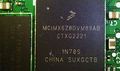
| + | NXP MCIMX6Z0DVM09AB<ref name="NXP MCIMX6Z0DVM09AB">https://www.nxp.com/part/MCIMX6Z0DVM09AB#/</ref> | ||
*[[ARM]] [[Cortex-A7]] running Linux | *[[ARM]] [[Cortex-A7]] running Linux | ||
| Line 25: | Line 29: | ||
*Has Arm TrustZone | *Has Arm TrustZone | ||
| − | ===Wifi/Bluetooth Module=== | + | ====Wifi/Bluetooth Module==== |
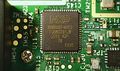
[[NXP]] 88W8987-NYE2<ref name="NXP 88W8987-NYE2">https://www.nxp.com/products/wireless-connectivity/wi-fi-plus-bluetooth-plus-802-15-4/2-4-5-ghz-dual-band-1x1-wi-fi-5-802-11ac-plus-bluetooth-5-2-solution:88W8987</ref> | [[NXP]] 88W8987-NYE2<ref name="NXP 88W8987-NYE2">https://www.nxp.com/products/wireless-connectivity/wi-fi-plus-bluetooth-plus-802-15-4/2-4-5-ghz-dual-band-1x1-wi-fi-5-802-11ac-plus-bluetooth-5-2-solution:88W8987</ref> | ||
| Line 31: | Line 35: | ||
*Bluetooth 5.2 (BLE also) | *Bluetooth 5.2 (BLE also) | ||
| − | ===Serial flash=== | + | ====Serial flash==== |
[[Winbond]] 25Q256JVEQ<ref name="Winbond 25Q256JVEQ">https://www.winbond.com/hq/product/code-storage-flash-memory/serial-nor-flash/?__locale=en&partNo=W25Q256JV</ref> | [[Winbond]] 25Q256JVEQ<ref name="Winbond 25Q256JVEQ">https://www.winbond.com/hq/product/code-storage-flash-memory/serial-nor-flash/?__locale=en&partNo=W25Q256JV</ref> | ||
| Line 37: | Line 41: | ||
*Dual/Quad SPI XIP (133MHz SPI) | *Dual/Quad SPI XIP (133MHz SPI) | ||
| − | ===RAM=== | + | ====RAM==== |
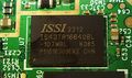
[[ISSI]] IS43TR16640BL<ref name="ISSI IS43TR16640BL">https://www.issi.com/WW/pdf/43-46TR16640B-81280BL.pdf</ref> | [[ISSI]] IS43TR16640BL<ref name="ISSI IS43TR16640BL">https://www.issi.com/WW/pdf/43-46TR16640B-81280BL.pdf</ref> | ||
| Line 43: | Line 47: | ||
*16bit DDR3 | *16bit DDR3 | ||
| − | === | + | ====Sub-GHz "EZRadio" Transceiver==== |
| + | Markings: 455A CQRX 220 | ||
| + | |||
| + | Silicon Labs Si4455<ref name=":0">https://www.silabs.com/documents/public/data-sheets/Si4455.pdf</ref> | ||
| + | |||
| + | *Frequency of 283–960 MHz | ||
| + | *–116 dBm Sensitivity | ||
| + | *Modulation: | ||
| + | **(G)FSK | ||
| + | **OOK | ||
| + | *+13 dBm Max output power | ||
| + | *50 nA Standby Current | ||
| + | *500 kbps Max Data Rate | ||
| + | *1.8 to 3.6 VDC <br /> | ||
| + | |||
| + | ===Rev A0 Blink Board=== | ||
| + | |||
| + | ====Microcontroller==== | ||
| + | [[Atheros]] AR9331 rev 1 (MIPS 24Kc @ 400MHz) - [https://github.com/luekker/blink-sync-module-2/blob/main/docs/Atheros%20-%20AR9331.pdf] | ||
| + | |||
| + | ====Wifi Module==== | ||
| + | Onboard [[Atheros]] AR9331 | ||
| + | |||
| + | ====Serial flash==== | ||
| + | [[Winbond]] 25Q64 | ||
| + | |||
| + | ====RAM==== | ||
| + | [[ISSI]] IS43TR16640BL<ref name="ISSI IS43TR16640BL" /> | ||
| + | |||
| + | *64mb DDR2 16 bit | ||
| + | |||
| + | ====Sub-GHz "EZRadio" Transceiver==== | ||
Markings: 455A CQRX 220 | Markings: 455A CQRX 220 | ||
| − | + | ||
| + | Silicon Labs Si4455<ref name=":0" /> | ||
| + | |||
| + | *Frequency of 283–960 MHz | ||
| + | *–116 dBm Sensitivity | ||
| + | *Modulation: | ||
| + | **(G)FSK | ||
| + | **OOK | ||
| + | *+13 dBm Max output power | ||
| + | *50 nA Standby Current | ||
| + | *500 kbps Max Data Rate | ||
| + | *1.8 to 3.6 VDC | ||
==Teardown pictures== | ==Teardown pictures== | ||
| + | |||
| + | ====Amazon Board==== | ||
| + | <gallery> | ||
| + | File:Blink syncmodule2 photo1.jpg|Front face of the BSM2 | ||
| + | File:Photo2.jpg|Back face of the BSM2 | ||
| + | File:Photo3.jpg|Top view | ||
| + | File:Photo4.jpg|To take off the top part just use a spudger, guitar pic, etc. No glue or screws to take the top cover off. | ||
| + | File:Photo5.jpg|PCB view (top) | ||
| + | File:Photo6.jpg|PCB view (top) closeup | ||
| + | File:Photo8.jpg|PCB view (bottom) | ||
| + | File:Photo9.jpg|Serial Flash closeup | ||
| + | File:Photo10.jpg|MCU closeup | ||
| + | File:Photo11.jpg|SRAM closeup | ||
| + | File:Unknown ic.png|Si4455 | ||
| + | File:Photo12.jpg|Wifi/BT module closeup | ||
| + | File:Bottom layer zoom.jpg | ||
| + | File:Sync module 2 top layer zoom.jpg | ||
| + | </gallery><br /> | ||
| + | |||
| + | ====Rev A0 - Blink Board==== | ||
| + | <gallery> | ||
| + | File:Blink-sync-module-2-shell.jpg|Outer shell | ||
| + | File:Blink Sync Module 2 - rev a0 - Pins.png|Labelled Pins, TM1 = RX, TM2 = TX, TM3 = GND | ||
| + | File:Blink sync module 2 PCB (top) - rev a0.jpg|Top face | ||
| + | File:Blink Sync Module 2 PCB (bottom) - Rev A0.jpg|Bottom face | ||
| + | </gallery> | ||
| + | |||
==Serial Communications== | ==Serial Communications== | ||
It is possible to read the boot of the device by connecting to the indicated pin. | It is possible to read the boot of the device by connecting to the indicated pin. | ||
Baud rate is 115200. | Baud rate is 115200. | ||
| − | |||
| + | ====Amazon Board==== | ||
| + | [[File:Txpin.png|none|frame]]<br /> | ||
| + | |||
| + | ====Rev A0 - Blink Board==== | ||
| + | TM2 for reading UART | ||
| + | [[File:Blink Sync Module 2 - rev a0 - Pins.png|none|thumb]]<br /> | ||
| + | |||
==References== | ==References== | ||
<references /> | <references /> | ||
Latest revision as of 00:31, 11 February 2026

Contents
What is it?
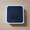
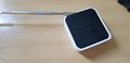
Home appliance to control other Amazon Blink devices.
According to the manufacturer: "The Sync Module is a hub that plugs into an electrical outlet to relay commands and network details to devices in the system it manages. The Sync Module 2 requires a power outlet and is connected to your always-on Wi-Fi network to handle activity for up to ten Blink devices. This extends camera battery life, saves clips without a subscription, improves convenience for scheduling, and arms a group of devices at once."[1]
What can it do?
- Control Blink devices (cameras, doorbells, etc) from the Blink mobile app
- Connect up to 10 of any Blink Outdoor 4, Wired Floodlight, Outdoor and Indoor (all models), XT2, XT, Video Doorbell*, and Mini* cameras.
- Support local video storage for up to 10 Blink cameras.
- Record and store motion clips when you insert a USB flash drive (up to 256 GB).
Main components
The Blink Sync Module 2 has 2 documented board types, they can easily be identified by the microprocessor being mounted on the bottom or top of the PCB, if the chip is on the bottom board rev = A0 Blink board.
Amazon Board
Microcontroller
NXP MCIMX6Z0DVM09AB[2]
- ARM Cortex-A7 running Linux
- 900MHz
- SRAM: 128kB
- SPI/UART/I2C
- 96KB bootrom, 128KB internal RAM
- Has Arm TrustZone
Wifi/Bluetooth Module
- 2.4/5Ghz Wifi
- Bluetooth 5.2 (BLE also)
Serial flash
- 256M-bit
- Dual/Quad SPI XIP (133MHz SPI)
RAM
- 1GB SDRAM
- 16bit DDR3
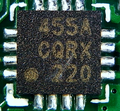
Sub-GHz "EZRadio" Transceiver
Markings: 455A CQRX 220
Silicon Labs Si4455[6]
- Frequency of 283–960 MHz
- –116 dBm Sensitivity
- Modulation:
- (G)FSK
- OOK
- +13 dBm Max output power
- 50 nA Standby Current
- 500 kbps Max Data Rate
- 1.8 to 3.6 VDC
Rev A0 Blink Board
Microcontroller
Atheros AR9331 rev 1 (MIPS 24Kc @ 400MHz) - [1]
Wifi Module
Onboard Atheros AR9331
Serial flash
Winbond 25Q64
RAM
- 64mb DDR2 16 bit
Sub-GHz "EZRadio" Transceiver
Markings: 455A CQRX 220
Silicon Labs Si4455[6]
- Frequency of 283–960 MHz
- –116 dBm Sensitivity
- Modulation:
- (G)FSK
- OOK
- +13 dBm Max output power
- 50 nA Standby Current
- 500 kbps Max Data Rate
- 1.8 to 3.6 VDC
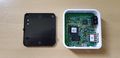
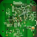
Teardown pictures
Amazon Board
Front face of the BSM2
Back face of the BSM2
Top view
To take off the top part just use a spudger, guitar pic, etc. No glue or screws to take the top cover off.
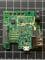
PCB view (top)
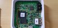
PCB view (top) closeup
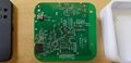
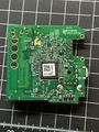
PCB view (bottom)
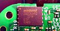
Serial Flash closeup
MCU closeup
SRAM closeup
Si4455
Wifi/BT module closeup
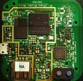


Rev A0 - Blink Board
Outer shell
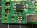
Labelled Pins, TM1 = RX, TM2 = TX, TM3 = GND
Top face
Bottom face


_-_rev_a0.jpg)
_-_Rev_A0.jpg)
Serial Communications
It is possible to read the boot of the device by connecting to the indicated pin.
Baud rate is 115200.
Amazon Board

Rev A0 - Blink Board
TM2 for reading UART
References
- ↑ [ https://support.blinkforhome.com/en_US/faq-sm/sync-module-2-faqs]
- ↑ https://www.nxp.com/part/MCIMX6Z0DVM09AB#/
- ↑ https://www.nxp.com/products/wireless-connectivity/wi-fi-plus-bluetooth-plus-802-15-4/2-4-5-ghz-dual-band-1x1-wi-fi-5-802-11ac-plus-bluetooth-5-2-solution:88W8987
- ↑ https://www.winbond.com/hq/product/code-storage-flash-memory/serial-nor-flash/?__locale=en&partNo=W25Q256JV
- ↑ 5.0 5.1 https://www.issi.com/WW/pdf/43-46TR16640B-81280BL.pdf
- ↑ 6.0 6.1 https://www.silabs.com/documents/public/data-sheets/Si4455.pdf