Difference between revisions of "Kenwood TH-D74A"
Jump to navigation
Jump to search
| Line 58: | Line 58: | ||
Initially the radio was opened and wires were soldered to test points and a port of interest as seen in the video below. | Initially the radio was opened and wires were soldered to test points and a port of interest as seen in the video below. | ||
| + | |||
| + | {{YouTube|id=EZP2DVU9IvQ|width=320|height=240}} | ||
====Understand how the radio works==== | ====Understand how the radio works==== | ||
Revision as of 00:59, 8 June 2020
Contents
Teardown Video
6 minute video @ 3x playback speed showing full disassembly of the radio with commentary, full length video with no audio here.
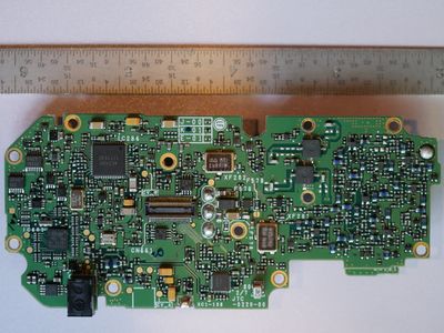
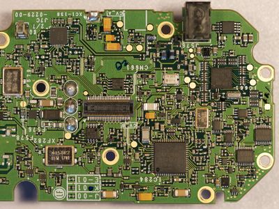
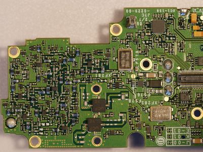
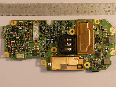
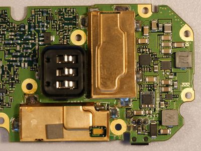
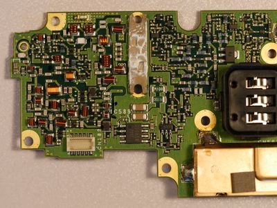
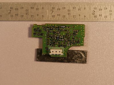
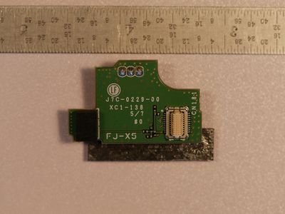
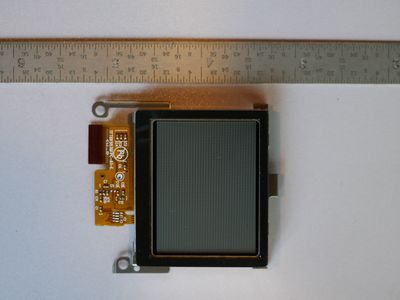
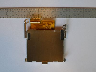
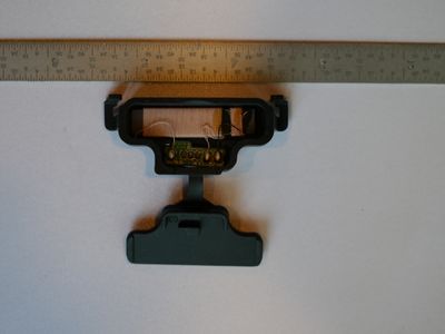
Teardown PCB Pictures
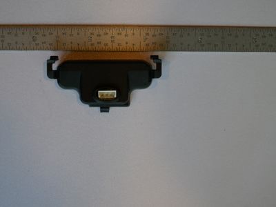
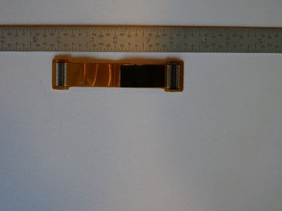
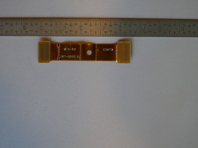
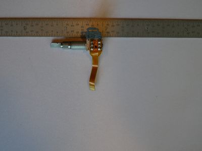
Modules and Interconnects
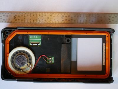
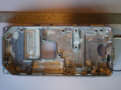
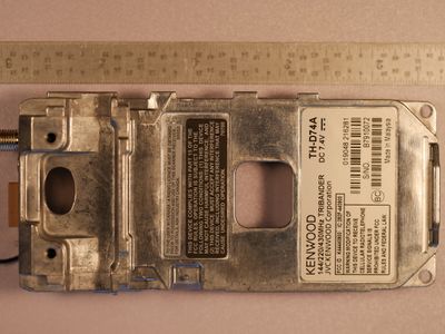
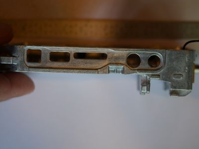
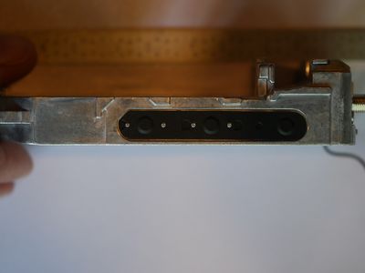
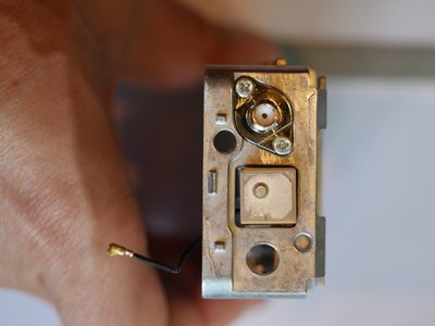
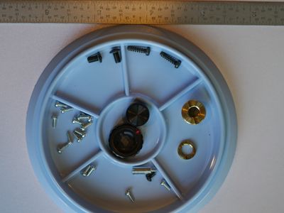
Mechanical Pictures
Reverse Engineering Efforts
High level goals
- Obtain a copy of the firmware for analysis/modification
- Understand how the radio works and what test ports are available internally
Obtaining firmware
- Determine routes of attack
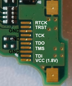
- JTAG Port
- Serial Port
- Hardware attack - Remove Flash Memory and read directly (possibly encrypted)
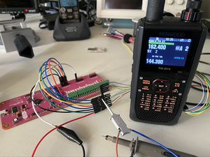
Initially the radio was opened and wires were soldered to test points and a port of interest as seen in the video below.
Understand how the radio works
Datasheets
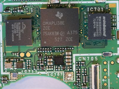
Kenwood TH-D74A Datasheet - IC-701 - DRAM
Kenwood TH-D74A Datasheet - IC-702 - omap-l138
