Neato XV-11
This content has been migrated from the old xv11hacking.com website
What is the Neato XV-11 you ask??
The Neato XV-11(Wikipedia) is a robot which vacuum’s your house. It is unlike any other however because it includes a low cost 360 degree laser distance scanner (LIDAR See Wikipedia). This can be removed from the XV-11 and used in your own robotics projects or used within the XV-11 with the help of the Robot Operating System (ROS). The pages within this wiki document interfacing methods into the XV-11 and is open to anyone who wants to help. For $399 you can’t find a better robotics platform in my opinion, definitely worth the cost even if you do nothing more than strip it down for parts. You will find it is very well constructed by some people who definitely know about robotics.
Contents
Connecting to ROS
ROS Driver
There is a ROS driver that connects to the XV-11 through the USB port, documentation can be found on the ROS wiki. This driver includes both an ROS-independent python implementation and an ROS node wrapper for the python implementation. It currently controls the mobile base, provides odometry feedback, and publishes laser scans. Future versions will include battery and sensor access features (the currently exist in the ROS-independent code, but have not yet been given a proper ROS API).
Install ROS on Ubuntu
The following procedure will help you install the Robot Operating System on Ubuntu 10.10 for use with the XV-11.
I have tested this running Ubuntu 10.10 as a VMware virtual machine as well as installed on a system as the booted OS. Ubuntu is a very easy to use Linux release you can download from here Now lets get started! Open a terminal by clicking on Applications -> Accessories -> Terminal Enter the following commands by copying and pasting them into the terminal window. Use CTRL-C to copy and then CTRL-SHIFT-V to paste them in the terminal window.
- sudo sh -c ‘echo “deb http://code.ros.org/packages/ros/ubuntu maverick main” > /etc/apt/sources.list.d/ros-latest.list’
- wget http://code.ros.org/packages/ros.key -O - | sudo apt-key add -
- sudo apt-get update
- sudo apt-get install ros-cturtle-base
The last command will install approximately 5GB worth of software so grab some coffee, a Rockstar, or your stimulant of choice! Once it is done installing run the commands below to install some more ROS software in your home folder.
- cd; mkdir ros; cd ros
- svn co https://brown-ros-pkg.googlecode.com/svn/tags/brown-ros-pkg/teleop_twist_keyboard
- svn co http://albany-ros-pkg.googlecode.com/svn/trunk/slam_coreslam/coreslam
- svn co http://albany-ros-pkg.googlecode.com/svn/trunk/neato_robot
- echo ‘. /opt/ros/cturtle/setup.sh’ >> ~/.bashrc
- echo ‘export ROS_PACKAGE_PATH=~/ros:${ROS_PACKAGE_PATH}’ >> ~/.bashrc
- source ~/.bashrc
- sudo su
- echo ‘. /opt/ros/cturtle/setup.sh’ >> ~/.bashrc
- echo ‘export ROS_PACKAGE_PATH=${ROS_PACKAGE_PATH}’ >> ~/.bashrc
- exit
- cd ~/ros/teleop_twist_keyboard; rosmake
- cd ~/ros/coreslam; rosmake
- cd ~/ros/neato_robot; rosmake
Now we will edit the /etc/modules file so the usbserial driver will be automatically loaded with the parameters needed. We also add the cdc_acm driver to the blacklist so it will not be used with the XV-11. On a Macbook Pro the system used this driver instead of usbserial.
- sudo su
- echo “usbserial vendor=0x2108 product=0x780B” >> /etc/modules
- echo “blacklist cdc_acm” >> /etc/modprobe.d/blacklist.conf
- modprobe usbserial vendor=0x2108 product=0x780B
- rmmod cdc_acm
- exit
Almost time to plug your XV-11 into the system!! For the sake of simplicity do not plug in any other USB to serial devices at this point. This will ensure your XV-11 appears as /dev/ttyUSB0 and will simplify setup at this point.
- ls /dev/ttyU*
Once you plug in the XV-11 you should see /dev/ttyUSB0 appear. Now lets load the XV-11 drivers.
- roslaunch neato_node bringup.launch
Entering the above command should initiate a connection to /dev/ttyUSB0 and after a couple seconds you will hear the LIDAR start to spin on the XV-11. Don’t worry if you don’t hear it, press CTRL-C to exit the driver then enter the command again. I have found it does not seem to start properly upon first load. Now press CTRL-SHIFT-T while your terminal window is selected to open a new tab within that terminal window, just like a new web browser tab. We will open a few of these tabs to load the different ROS drivers/programs.
- roslaunch 2dnav_neato move_base.launch
- (open a new tab before running the next command)
- rosrun rviz rviz
Just to verify, you should have three tabs open now with these three commands simultaneously running. SWEET HUH!! Now you have the GUI application running, just a couple more steps and its play time! On the top menu bar click Plugins -> Manage then click the box next to Loaded and click OK. There is a video here with details on setting up RViz. You can use this file with RViz and it has all those parameters already setup. Right click on the file and save it. Within RViz just go to File -> Open Config and select the XV11.vcg file. Now open a new terminal which we will use for keyboard control to manually navigate the XV-11.
- rosrun teleop_twist_keyboard teleop_twist_keyboard.py
You will see which keys are used to navigate on the screen once the program is running. The default speed settings are too fast for the XV-11 so you need to reduce the speed before it will respond to any input. Repeatedly press the “x” key to reduce speed when traveling in a straight line to about 0.10 and then do the same with the “c” key to reduce rotational speed to about 0.15. Now you can use the keyboard keys to navigate.
From this point you need to create your own map using gmapping and save the map so a map of your area is loaded when launching 2dnav_neato. gmapping needs to be modified from the base install on your system at this point to correct the reversed laser scan data. This wiki will be updated shortly with that procedure. gmapping is what will allow you to create a map of your surroundings which you will use to navigate.
Disassembly and Reassembly
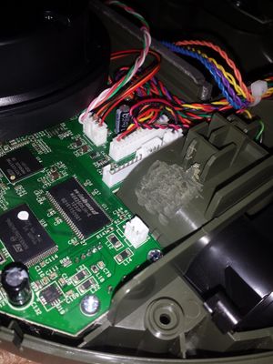
Pictorial instructions for disassembling and reassembling an XV-11 can be found at the Homebrew Robotics Club wiki linked off of the page: Dave’s XV-11 Notes. There are a few other XV-11 notes there as well, such as how to tap into the battery supply, and I’ll be adding more as I go along. I’m too lazy to update two wiki’s so I’ve decided to make the HBRC wiki my ‘home’ and cross-link from here to there and there to here. Anyway, the disassembly/reassembly instructions were done because I kept forgetting where all the screws go.
Hope it helps.
Hacking with Neato Firmware
Neato Firmware v2.6
A version 2.6 Neato XV-11 can be reverted to a previous firmware by pressing and holding the Back button (curved arrow) and the orange Start button at the same time for 4 seconds. When the robot reboots it will be running an older firmware with all the previous commands available.
Hidden Neato menu in newer 2.6 firmware!
Anyone who has updated their Neato firmware will notice a new message is returned when you enter ” Help” when connected to the robots USB port. Entering Help with a space before it used to return an extended hidden help menu with a lot more commands! When Neato released the 2.6 firmware update (or maybe earlier?) they removed the ” Help” and instead you got this response...
Nice try, but I’m not falling for that one again! :P
Some commands such as “SetStreamFormat” let you actually SEE what the robot is doing while driving around and mapping the environment internally. Some of the guys on Trossen Robotics forum (Chunk) have made really good progress using the output from this command! Sadly this is one of the commands removed from the 2.6 firmware version. But not for long!!
If you just press and hold the orange Start button and Back button at the same time for 4 seconds the robot will reboot into a different firmware that includes all those previous commands! Below is a capture from the on-board 4 pin serial port that shows debug data while the XV-11 is booting.
This capture is of the normal reboot (just holding the orange Start button for 4 seconds)
Neato Robotics XV-11/XEB V11:16:01
Copyright (c) 2006-2010 Neato Robotics, Inc

Loading installed application
Starting app
NEROSConfigErr: BlowerType=-1 (Expected 0
ConfigErr: BrushMotorType=-1 (Expected 0
ConfigErr: SideBrushType=-1 (Expected 0
FCB Invalid! Configurations may need to be initialized.

 Build 15840 Nov 14 2011 16:09:19

Init A2D
Configure power to STANDBY.
uart0EnablePeripheral
Power On reset: 8 :Software
DEBUG compile

Edison Design Group compiler

Init Pushbuttons.Finished halInit();
Sending GetVersion...
RCVD: Finished LDS getversion cmd in 5 ms
LDS reports build , we need build 15295 (size=16512)
Stop LDS driver to prevent contention
[]
Finished LDSBurn.
Sending GetVersion...
RCVD: Finished LDS getversion cmd in 4 ms
mmcReset Error

PH-drvrInit:Ignoring detected battery type because XV11.
PH-drvrStart:vacuumType(): Invalid SCB blower value. How did we get here?!
This capture is after holding the Start and Back buttons for 4 seconds.
Neato Robotics XV-11/XEB V11:16:01
Copyright (c) 2006-2010 Neato Robotics, Inc

Loading factory application
Starting app
NEROS Build 12882:12959 Jul 26 2010 22:38:28

Init A2D
Configure power to STANDBY.
uart0EnablePeripheral
Power On reset: 8 oftware
DEBUG compile

Edison Design Group compiler
Enabling USB-CDC ...

Crashblock file: @ 0
Crashblock fn:
Crashblock TOS:0x00000000
Crashblock watchvalues:

Init Pushbuttons.Finished halInit();
mmcReset Error

PH-drvrInit:
PH-drvrStart:
It appears this may be a secondary firmware loaded as a failsafe in case a USB firmware upgrade fails. This would make tech support easier as you have a firmware to revert too in case something goes wrong. You can see from the dates in each print out that they are completely different builds. Thanks to Theo Deyle for e-mailing me and inspiring me to work on this some more! Hopefully his own hacks will be posted soon as well!
Neato Firmware v3.0
The Neatos that are delivered with Firmware 3.0 are a different hardware revision compared to previous models.
Previous versions (incl. the Vorwerk VR100) are codename ‘Cruz’.
The new hardware revision has codename ‘Binky’.
There’s a bootloader you can get into on my XV25/Binky. I don’t know if this is unique for Binky:
testmode on
setsystemmode PowerCycleCDC
The Neato then disappears from the USB, and reappears with a limited CLI that doesn’t local echo and doesn’t support most commands I’ve tried.
help
Cmd not recognized.
getversion
NeatoBootVer,2.0,0
upload code
File size invalid
There’s more, but be careful.
Also, don’t try to stuff the Vorwerk update into here.
That’s for Cruz, and will probably brink your Binky.
Here’s the version data before upgrade:
getversion
Component,Major,Minor,Build
ModelID,-1,XV25,
ConfigID,2,,
Serial Number,XXX00000XX,0015662,P
Software,3,0,17235
BatteryType,1,NIMH_12CELL,
BlowerType,1,BLOWER_ORIG,
BrushSpeed,1200,,
BrushMotorType,1,BRUSH_MOTOR_ORIG,
SideBrushType,1,SIDE_BRUSH_NONE,
WheelPodType,1,WHEEL_POD_ORIG,
DropSensorType,1,DROP_SENSOR_ORIG,
MagSensorType,1,MAG_SENSOR_ORIG,
WallSensorType,1,WALL_SENSOR_ORIG,
Locale,1,LOCALE_USA,
LDS Software,V2.6.15295,0000000000,
LDS Serial,XXX00000XX-0000000,,
LDS CPU,F2802x/c001,,
BootLoader Software,17225,P,p
MainBoard Vendor ID,543,,
MainBoard Serial Number,000000000000000000000000,,
MainBoard Software,17242,1,
MainBoard Boot,16219,
MainBoard Version,4,0,
ChassisRev,2,,
UIPanelRev,1,,
testmode on
testlds cmd getversion
Sending getversion...
getversion

GetVersion...3 ESCs or BRAK to abort...:)
Piccolo Laser Distance Scanner
Copyright (c) 2009-2011 Neato Robotics, Inc.
All Rights Reserved

Loader    V2.5.14010
CPU    F2802x/c001
Serial    XXX00000XX-0000000,,
LastCal    5371726C
Runtime    V2.6.15295
OK
#testmode off
This is after the upgrade
getversion
Component,Major,Minor,Build
ModelID,-1,XV25,
ConfigID,2,,
Serial Number,XXX00000XX,0015662,P
Software,3,1,17844
BatteryType,1,NIMH_12CELL,
BlowerType,1,BLOWER_ORIG,
BrushSpeed,1200,,
BrushMotorType,1,BRUSH_MOTOR_ORIG,
SideBrushType,1,SIDE_BRUSH_NONE,
WheelPodType,1,WHEEL_POD_ORIG,
DropSensorType,1,DROP_SENSOR_ORIG,
MagSensorType,1,MAG_SENSOR_ORIG,
WallSensorType,1,WALL_SENSOR_ORIG,
Locale,1,LOCALE_USA,
LDS Software,V2.6.15295,0000000000,
LDS Serial,XXX00000XX-0000000,,
LDS CPU,F2802x/c001,,
MainBoard Vendor ID,543,,
MainBoard Serial Number,555,,
BootLoader Software,17225,P,p
MainBoard Software,17624,1,
MainBoard Boot,16219,
MainBoard Version,4,0,
ChassisRev,2,,
UIPanelRev,1,,
testmode on
testlds cmd getversion
Sending getversion...
getversion
GetVersion...3 ESCs or BREAK to abort...:)
Piccolo Laser Distance Scanner
Copyright (c) 2009-2011 Neato Robotics, Inc.
All Rights Reserved

Loader V2.5.14010
CPU F2802x/c001
Serial XXX00000XX-0000000,,
LastCal 5371726C
Runtime V2.6.15295
OK
#testmode off
Interfacing with LIDAR Sensor
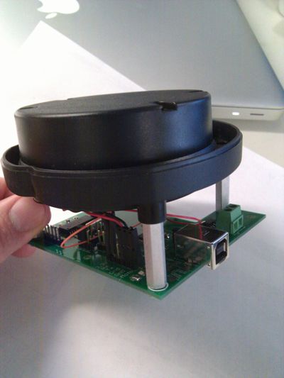
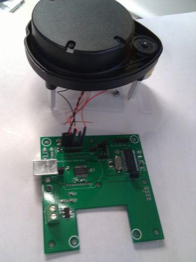
I created a board to interface the LIDAR sensor to a PC without the rest of the XV-11. The PCB consists of a PIC18F2221, and FTDI-232R, a 3.3V regulator, and a Fet for controlling the motor. The pic watches the data from the LIDAR and uses the speed information to control the PWM pin attached to the FET. In this way the correct speed can be maintained. The Firmware for the pic currently only supports the old LIDAR firmware ( that is what I have). Hopefully someone else can modify it to work with the other firmware as well. There are jumpers for configuring who talks to what between the PC, PIC, and LIDAR. There are also options for supplying your own 5V instead of getting it from USB and an option for using an XBEE for wireless communication. Schematics are posted below as well as the Eagle brd files. Source code for the PIC will be posted soon. I have spare boards for sale if anyone is interested. Ringo (dot) Davis (at) gmail (dot) com.
LIDAR API Commands
Commands available from the LIDAR via direct serial connection or through the Main PCB API To access the API directly via the serial connection of the sensor, send an ESCAPE character (0x1B). The lidar then responds with an invite : “#” You can then enter commands (below is the result of Help command, some additional hidden commands are probably available)
#
# Help
GetVersion
Help
Log
SaveCal
SetSerial
Upload
Wanderer
Calibrate b16 b8 SunBlind loop2AA loop155
GetCal A B C LPT LFL LFT LFH IMX IB LPI LCH LPD ANG
SetCal A B C LPT LFL LFT LFH IMX IB LPI LCH LPD ANG
Spin Fake DotX DotI Text Hash Timing Foto RPS Pac
TestEncoder
Commands are case-insensitive, and can be entered incompletly : getversion, getvers, getv, GeTvErSiOn will all work alike. Be aware that one at least of these commands can brick your LDS... Here are the details of what is currently known about these commands: (To be completed!)
GetVersion
Prints informations about the version of the LDS. Example:
GetVersion...press ESC 3 times to abort...OK
Piccolo Laser Distance Scanner
Copyright (c) 2009-2010 Neato Robotics, Inc.
All Rights Reserved

Loader V2.4.13386
CPU F2802x/c600
Serial AAA42110AA-0003616
LastCal [2010110136]
Runtime V2.4.13386
SUCCEEDED
Help
Prints a list of available commands. Example:
Help...press ESC 3 times to abort...
  GetVersion
  Help
  Log
  SaveCal
  SetBaud
  SetSerial
  Upload
  Wanderer
  Calibrate b16 b8 SunBlind loop2AA loop155
  GetCal A B C LPT LFL LFT LFH IMX IB LPI LCH LPD ANG
  SetCal A B C LPT LFL LFT LFH IMX IB LPI LCH LPD ANG
  Spin Fake DotX DotI Text Hash Timing Foto RPS Pac
  TestEncoder
SUCCEEDED
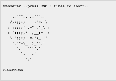
Wanderer
Draws a squirrel in a heart, in ASCII art... Example:
LIDAR Mechanical Info
Place any info here relating to mechanical aspects of the LIDAR.
- Weight: ~195.3g
- Use TE 440054-4 and TE 440054-2 for the 4-pin signal and 2-pin power connectors (thanks chenglung)
- You can get free samples of these parts from TE’s website
2D CAD files of the XV-11’s LIDAR unit, in mm. Thanks goes to chenglung from the trossen robotics forums.
3D CAD model of the LIDAR unit. Note that I used the 2d cad files mentioned above along with my own measurements, so be warned that the following is not completely accurate. Also, I’m no CAD professional, so you won’t find much detail in the model - just enough to account for any significant design properties which may be useful to know when building the module into your own applicatio
XV-11 LIDAR Mechanical Files contains the following
- 2D CAD Files
- XV-11_LDS CAD.zip
- XV-11 LDS.pdf
- 3D CAD Files
- xv-11_lidar.SLDPRT
- xv-11_lidar.STL
- xv-11_lidar.IGS
- xv-11_lidar.PDF
If anyone needs the file in some other format, just send me a request and I’ll try to help you out: rus.tech.studio ‘@’ gmail.com
LIDAR Sensor
The LIDAR sensor is what started this entire project. Find all the information you need below.
The angle of the data is not aligned with the natural axis of the device. It seems that the first sample of the first packet is in fact looking at a -10° angle, not 0°. Needs confirmation.
Data format for firmware V2.4
(recent production units)
A full revolution will yield 90 packets, containing 4 consecutive readings each.
The length of a packet is 22 bytes.
This amounts to a total of 360 readings (1 per degree) on 1980 bytes.
Each packet is organized as follows:
start byte index speed Data 0 Data 1 Data 2 Data 3 checksum
where:
- start byte is always 0xFA
- index is the index byte in the 90 packets, going from 0xA0 (packet 0, readings 0 to 3) to 0xF9 (packet 89, readings 356 to 359).
- speed is a two-byte information, little-endian. It represents the speed, in 64th of RPM (aka value in RPM represented in fixed point, with 6 bits used for the decimal part).
- Data 0 to Data 3 are the 4 readings. Each one is 4 bytes long, and organized as follows :
byte 0 : Distance 7:0
byte 1 : “invalid data” flag : “strength warning” flag
byte 2 : Signal Strength 7:0
byte 3 : Signal Strength 15:8
As chenglung points out, the distance information is in mm, and coded on 14 bits. This puts the tests made by Sparkfun in a room of around 3.3m x 3.9m (11ft x 13 ft ?), which seems reasonable.
The minimum distance is around 15cm, and the maximum distance is around 6m.
When bit 7 of byte 1 is set, it indicates that the distance could not be calculated. When this bit is set, it seems that byte 0 contains an error code. Examples of error code are 0x02, 0x03, 0x21, 0x25, 0x35 or 0x50...
When it’s `21`, then the whole block is `21 80 XX XX`, but for all the other values it’s the data block is `YY 80 00 00`...
The bit 6 of byte 1 is a warning when the reported strength is greatly inferior to what is expected at this distance. This may happen when the material has a low reflectance (black material...), or when the dot does not have the expected size or shape (porous material, transparent fabric, grid, edge of an object...), or maybe when there are parasitic reflections (glass... ).
Byte 2 and 3 are the LSB and MSB of the strength indication. This value can get very high when facing a retroreflector.
- checksum is a two-byte checksum of the packet.
The algorithm is as follows, provided that `data` is the list of the 20 first bytes, in the same order they arrived in.
def checksum(data):
 “”“Compute and return the checksum as an int.”“”
 # group the data by word, little-endian
 data_list = []
 for t in range(10):
   data_list.append( data2*t + (data2*t+1<<8) )

 # compute the checksum on 32 bits
 chk32 = 0
 for d in data_list:
   chk32 = (chk32 << 1) + d

 # return a value wrapped around on 15bits, and truncated to still fit into 15 bits
 checksum = (chk32 & 0x7FFF) + ( chk32 >> 15 ) # wrap around to fit into 15 bits
 checksum = checksum & 0x7FFF # truncate to 15 bits
 return int( checksum )
Data format for firmware 2.1
(Sparkfun scans, pre-production units)
The periodicity of the data is 1446 bytes.
It is organized as follow :
5A A5 00 C0 XX XX data
where `XX XX` is an information about the current rotation speed of the module, in clock ticks (little endian). http://forums.trossenrobotics.com/showthread.php?t=4470&page=5 posted interesting data about this.
`` is composed of 360 group of 4 bytes, organized like this :
byte 0 : Distance 7:0
byte 1 :  “invalid data” flag : ”quality warning” flag : distance 13:8
byte 2 : Quality 7:0
byte 3 : Quality 15:8
As chenglung points out, the distance information is in mm, and coded on 13 or 14 bits. This would put the tests made by Sparkfun in a room of around 3.3m x 3.9m (11ft x 13 ft ?), which seems reasonable to me. 13 bits should be enough if the sensor is destined to work up to 6m. This needs some tests...
The bit 7 of byte 1 seems to indicate that the distance could not be calculated.
It’s interesting to see that when this bit is set, the second byte is always `80`, and the values of the first byte seem to be only `02`, `03`, `21`, `25`, `35` or `50`...
When it’s `21`, then the whole block is `21 80 XX XX`, but for all the other values it’s the data block is `YY 80 00 00`
maybe it’s a code to say what type of error ? (`35` is preponderant, `21` seems to be when the beam is interrupted by the supports of the cover) .
Another thing to have a look to is the temporal repartition of the data... the first sample after the sync seems to always be `21 80 XX XX`, and when this pattern appears again, it’s immediately after an other value, without the 0.2ms interval we can see most of the time between two blocks of 4...
The bit 6 of byte 1 is a warning when the reported strength is greatly inferior to what is expected at this distance. This may happen when the material has a low reflectance (black material...), or when the dot does not have the expected size or shape (porous material, transparent fabric, grid, edge of an object...), or maybe when there are parasitic reflections (glass... ).
Byte 2 and 3 are the LSB and MSB of the strength indication. This value can get very high when facing a retroreflector.
Motors
Data on the drive motors, brush motor, and vacuum fan.
SetMotor Command
Motor speeds can be set using the SetMotor commands. This command is handled asynchronously, so you can query other commands while the robot is moving. The simplest way to set both the left and right motor speed is to use:
SetMotor left_dist right_dist speed
Where left_dist and right_dist are a distance to travel in millimeters, and speed is the speed to use for movement in millimeters per second. Speed must be positive, and at least one of left_dist or right_dist must be non-zero. Drive motor speeds are -300 mm/s to 300 mm/s. These max speeds also induce a rotational max speed of approximately +/- 2.25 radians/sec given the separation of the wheels.
It appears that when different distances are put in, the speed will be applied to the wheel moving the farther distance, and the other wheel will be scaled such that both wheels take the same amount of time to travel their complete distance. (Can someone confirm this on their bot? - Fergy).
Some examples:
- SetMotor 100 100 100 - will move the robot forward 100mm, in approximately one second
- SetMotor 100 -100 100 - will turn the robot to the right in place, for 1 second.
- SetMotor 100 200 100 - the robot will move forward and to the left, for 2 seconds.
The base width separation of the wheel is approximately 248 millimeters. Therefore, the circumference when turning in place is approximately 780 millimeters. Thus, we can turn the robot using:
- SetMotor 195 -195 100 - the robot will turn in place, 90 degrees to the right.
Neato XV series WiFi remote control
Neato is great in cleaning by it self, it also has good “spot clean” algorithm! But, what if you want to clean just a certain spot? In other words - use it like a regular vacuum?
That was the basic idea which led to realization of the full wireless remote control.
As you may know, you can manually control Neato right out of the box by connecting it to any computer via usb and, through any terminal program, send commands to robot (for some reason article describing command list on official Neato site is unreachable at this moment, but you can get it by typing ‘help’). The way you can control Neato movements is described here: XV-11 API Commands
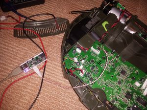
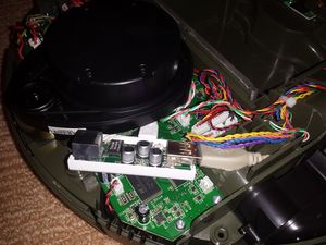
This is really great, but how can one use it for robot’s intended purpose if he or she is limited by the length of the wire? Of course you can take a laptop! But for me it was not the answer. Luckily, my friend recently has brought a compact (very compact) WiFi router (Commonly available from eBay as “2g/3g/4g wifi router”, also known as HAME MPR-A5 and MIFI-F5. MPR-A1 and clones are likely to work as well if you manage to fit them in. Some additional material is available on http://my-embedded.blogspot.com/2013/12/mini-4g-router-rt5350f.html) and suggested that we should try to embed it into my Neato.
So, it was obvious that all we needed was to find +5V power supply and connect usb from router to neato’s usb. All that sounds simple, so we did it. (i should say that my Neato has rev.64 main board)
Very soon we realized that, first of all - there is no powerful enough +5V source on the main board, and the second one - Neato’s software blocks it from normal functioning if it senses power supply on its usb
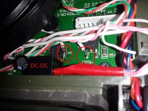
The answer to the first problem was as simple as buying 5V 500mA DC-DC converter (DC-DC on digikey.com) A local shop had Peak PSR-7805LF available for a reasonable price so I settled on that one.
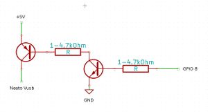
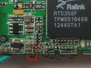
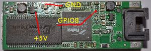
Answer to the second problem was a bit tricky! On the router board there is a source of power which can be turned on/off by changing state of its GPIO8 (echo 1 >/sys/class/gpio/gpio8/value), so my friend suggested that we will be able to control usb power supply by one P-N-P transistor witch base must be connected to that gpio. All that going to be great if only router could gave us +5V, but its voltage is only +3.3V. In the end the answer was found: we’d connected +5V from DC-DC to the Neato’s usb through one p-n-p and one n-p-n transistor (with a pair of resistors) controlled by the router’s +3.3V as shown below.
So now i have a fully functional Neato with a full control from any place in the world ;) I can remotely start cleaning in full cycle, or change its schedule, or use it full manual, or, even, just play like with RC car!
