Difference between revisions of "B&G International Decapsulator Model 250"
| (One intermediate revision by the same user not shown) | |||
| Line 34: | Line 34: | ||
==Control Unit Pictures== | ==Control Unit Pictures== | ||
| − | <gallery mode="packed" heights=" | + | <gallery mode="packed" heights="200"> |
File:BG Model 250 Controller Front.jpg|Front panel with LCD screen and 6 button keypad for loading programs and controlling various built-in maintenance features. | File:BG Model 250 Controller Front.jpg|Front panel with LCD screen and 6 button keypad for loading programs and controlling various built-in maintenance features. | ||
File:BG Model 250 Controller Back.jpeg|Rear with DB9 and DB25 connections on the left. DB9 supports RS232 and DB25 is from the IO Board which connects to the Acid Etching unit to control all the valves and read values back. Fan, power switch and plug on the right. | File:BG Model 250 Controller Back.jpeg|Rear with DB9 and DB25 connections on the left. DB9 supports RS232 and DB25 is from the IO Board which connects to the Acid Etching unit to control all the valves and read values back. Fan, power switch and plug on the right. | ||
File:BG Model 250 Controller Control Panel PCB.jpeg|Rear of LCD PCB seen on the top, bottom is PCB used for reading buttons and signal conditioning for LCD. | File:BG Model 250 Controller Control Panel PCB.jpeg|Rear of LCD PCB seen on the top, bottom is PCB used for reading buttons and signal conditioning for LCD. | ||
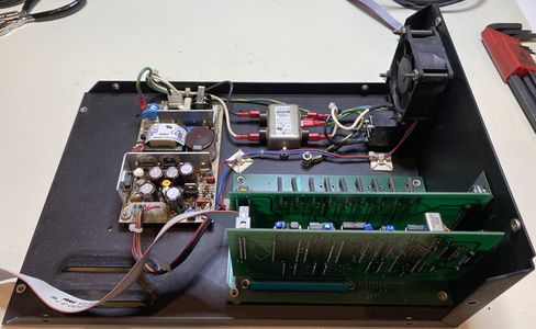
| + | File:BG Model 250 Controller Internal 1.jpeg|Power supply on the right with EMI Suppression on the bottom. Control PCB's on the top with ribbon cable that plugs into front panel PCB. | ||
| + | File:BG Model 250 Controller Internal 2.jpeg|Internal view from the other side | ||
| + | File:BG Model 250 Controller Processor Board.jpeg|Processor board runs on a Motorola 6803 8-bit microcontroller at 4.9152 MHz with an external 8k RAM, 64k EEPROM and a 256k EPROM with version sticker on it. | ||
| + | File:BG Model 250 Controller Processor Board Back.jpeg|Back of processor board, small jumper wire seen on the top right side. This is present on two different processor PCB's I have, not just a manufacturing defect with this board. | ||
| + | File:BG Model 250 Controller IO Board Front.jpeg|IO Board used to drive valves in Acid Etching unit. a buzzer is on the bottom middle which is triggered when there are errors or user interaction needed in the process. | ||
| + | File:BG Model 250 Controller IO Board IC.jpeg|Close up image of the IC's used | ||
| + | File:BG Model 250 Controller IO Board Transistor2.jpeg|Close up image of the transistors on the left used to drive the valves, driven by the smaller ones on the right. | ||
| + | File:BG Model 250 Controller IO Board Transistor.jpeg|Close up image of the transistors the Processor board drives which in turn drive the larger ones on the right that control the valves. | ||
| + | File:BG Model 250 Controller Backplane Top.jpeg|Backplane PCB which the processor board and IO board plug into, the black connector at the top is where the power supply connects. A ground trace is run to the nut on the top left which mounts to the chassis. The paint on the chassis around this screw was removed to make a good connection. | ||
| + | File:BG Model 250 Controller Backplane Bottom.jpeg|Botton of the backplane PCB, nuts are riveted to the PCB which mount to the bottom of the metal chassis. | ||
</gallery> | </gallery> | ||
* | * | ||
Latest revision as of 19:33, 28 June 2020

This tool is used to remove the epoxy package covering the silicon wafer of an integrated circuit, referred to as decapping. This is done by spraying acid into a contained temperature controlled area for a pre-determined period of time. The time, temperature and volume of acid can be controlled by creating programs which are saved within the machine. This leads to repeatable results when decapping IC's for failure analysis, reverse engineering or other endeavors.
This machine appears to be a very early model developed in the mid 1990's by Nisene Technology Group formerly known as B&G International. According to their website, it was the first to feature dual acid etching (Nitric and Sulphuric) technology.

Documentation for this specific unit is nowhere to be found online, every picture or reference to the machine shows paper manuals and all the usual searches on company websites return no results. Nisene was contacted directly but they stated they had no record of any material on this unit.
Some documentation describing similar machines below
- Patent 5,766,496 - Decapsulator and method for decapsulating plastic encapsulated device.
- This patent references the Model 250 as prior art and presents an improvement whereby less acid is used and it appears tighter control over the temperature. The Model 250 heats up a larger area where the IC is placed, this patent seems to describe heating only the acid jet reducing time to decapsulate.
This image from the book "Product Integrity and Reliability in Design" appears to be a schematic of the Model 250.,_John_W._Evans,_Jillian_Y._Evans_(eds.)_-_Product_Integrity_and_Reliability_in_Design-Springer-Verlag_London_(2001).jpg)
Acid Etching Unit Pictures
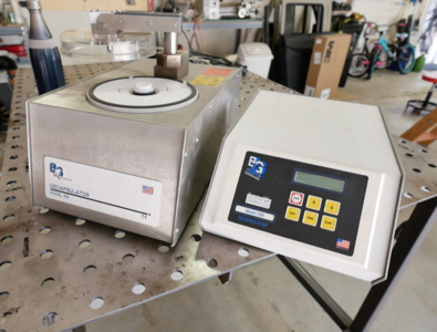
Decapsulator on the left and control box on the right. Control box contains all microprocessors and control logic.
Decapsulator with top and side covers removed.
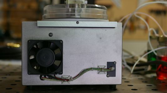
Decapsulator rear with hose attached to Nitrogen port. DB25 and power connector seen on the right. Holes on the left had Swagelok connectors that were removed and PTFE tube run straight from internal ports to external containers.
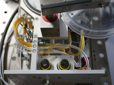
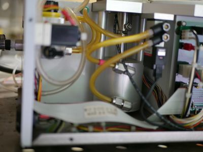
Pressure regulators at the bottom of the image to regulate Nitrogen used to control acid valves and large cylinder that opens/closes chamber.
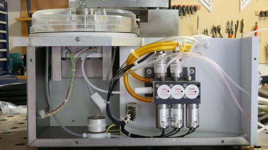
Valves used to control which acid is drawn in (Nitric or Sulphuric) and pump into chamber where IC is placed.
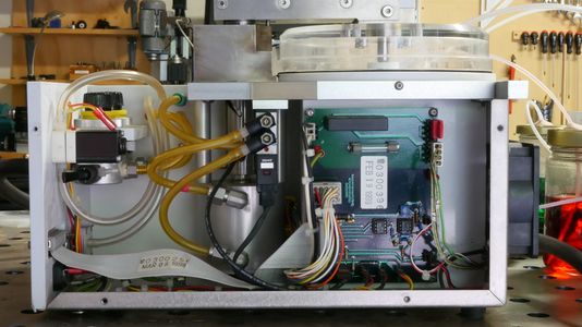
Etcher PCB with relay and components, large cylinder used to raise/lower lid and various valves/pressure sensors.
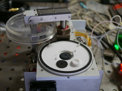
Etching chamber, when lid is lowered a seal is formed and the chamber is pressurized with Nitrogen. An error is presented to the user if an adequate seal is not formed.
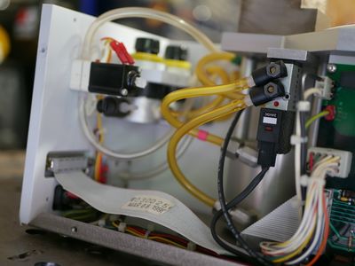
Side/Rear view showing acid valves and chamber. The lid of the chamber lifts and rotates using a groove cut into the shaft.
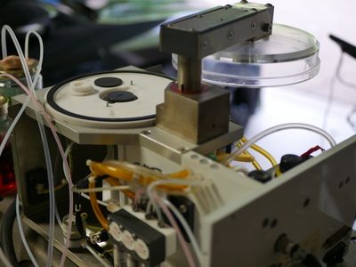
View of the large cylinder used to lift the lid and the pressure valve that feeds Nitrogen in to either lift or lower the lid.
Another view showing the pressure regulators and valve used to control large cylinder.
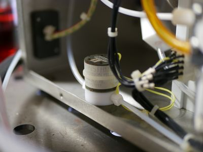
Pressure relief valve used to release pressure in the chamber. Pressure is vented out to the waste acid capture container. This container must not be sealed unlike the fresh acid containers which are sealed.
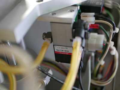
Close up picture of the valve used to control the large cylinder that lifts/lowers the chamber lid.


Control Unit Pictures
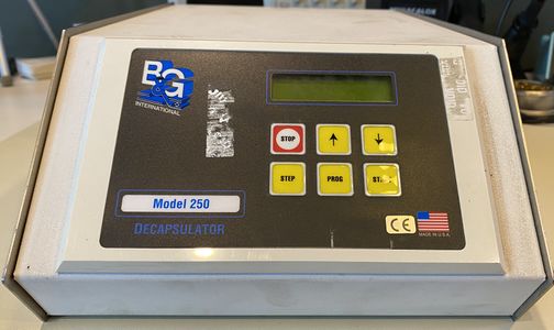
Front panel with LCD screen and 6 button keypad for loading programs and controlling various built-in maintenance features.
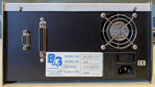
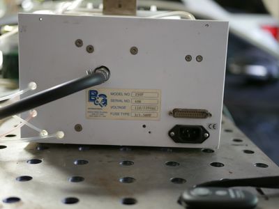
Rear with DB9 and DB25 connections on the left. DB9 supports RS232 and DB25 is from the IO Board which connects to the Acid Etching unit to control all the valves and read values back. Fan, power switch and plug on the right.
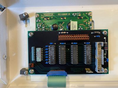
Rear of LCD PCB seen on the top, bottom is PCB used for reading buttons and signal conditioning for LCD.
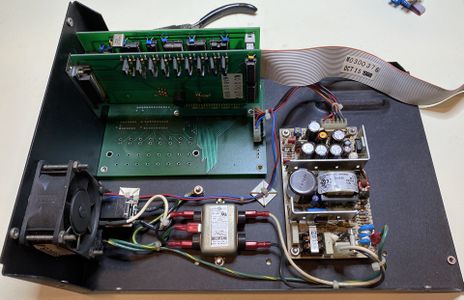
Power supply on the right with EMI Suppression on the bottom. Control PCB's on the top with ribbon cable that plugs into front panel PCB.
Internal view from the other side
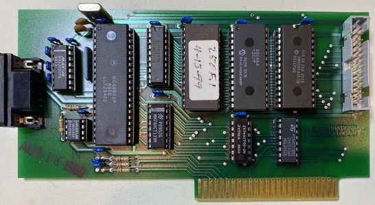
Processor board runs on a Motorola 6803 8-bit microcontroller at 4.9152 MHz with an external 8k RAM, 64k EEPROM and a 256k EPROM with version sticker on it.
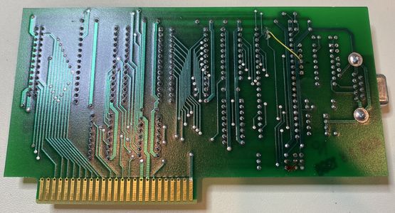
Back of processor board, small jumper wire seen on the top right side. This is present on two different processor PCB's I have, not just a manufacturing defect with this board.
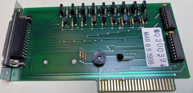
IO Board used to drive valves in Acid Etching unit. a buzzer is on the bottom middle which is triggered when there are errors or user interaction needed in the process.
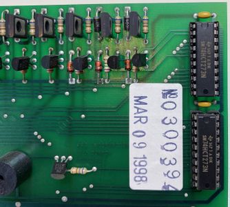
Close up image of the IC's used
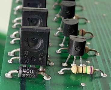
Close up image of the transistors on the left used to drive the valves, driven by the smaller ones on the right.
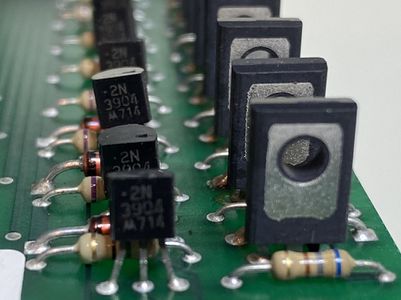
Close up image of the transistors the Processor board drives which in turn drive the larger ones on the right that control the valves.
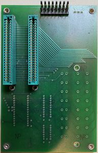
Backplane PCB which the processor board and IO board plug into, the black connector at the top is where the power supply connects. A ground trace is run to the nut on the top left which mounts to the chassis. The paint on the chassis around this screw was removed to make a good connection.
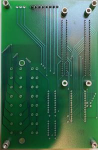
Botton of the backplane PCB, nuts are riveted to the PCB which mount to the bottom of the metal chassis.


